zKars
 Subscriber
-
Joined
-
Last visited
Everything posted by zKars
-
 The good news is, fill until it hits the bottom of the fill hole. That's the "right" amount. The volumes listed are average expected capacities. If you're filling through another hole since you can't get the fill plug out, well then use the listed quatities. You are just witnessing documentation and the evolution of said documentation. I remember this was discussed in another thread where several variances in wording and quantities were hi-lighted between different FSM years. Some made it explicit to "fill until it runs on your shoe" while others just listed the capacities. I think everyone agreed that "full" is the right amount and now worry about an oz/decalitre/micro-pint here or there. Just checking the 76 FSM, the paragraph reads "1.6 liters ( 3 3/8 US pt) 2 7/8 imp Pt." so the 2 3/8" in the 73 manual is wrong. Actually the 73 manual in the text on bottom of page TM-11 says "1.6 litres (3 3/8 US gal 3/4 Imper. gal) "!! there is no "2" on the 3/4!!! Katayama would roll over on his couch if he saw that! Apparently they had other more pressing emergencies to deal with 73 than proof reading the documentation.... Like how to get those flat tops to return the emmisions specs they needed.....
 -
TinyZ: First welcome to the Z obsession! Is your current wiring harness really in such bad shape that you feel you have to replace it all? The Factory Service manual for your 73 is available here. XenonS30 The "Body Electrical" (BE) section has the schematics and wiring connector layout diagrams you'll need. I have to say that the effort to understand the current wiring, so that it can be replaced with new, and then doing that replacement, tends to be far more difficult and time consuming than taking the understanding you gained in part one (understanding what you have now) and just fixing those parts of your harness that need it. We call this the "painless wiring syndrome".... There ain't no such thing as a "painless" wiring harness replacement. If your engine bay harness/dash harness is "that" bad, you might put an "want to buy" ad on here anyway. You might be surprised how affordable one can be if you ask. hint hint.... There also lots of electrical experts here that can help with specific questions. After looking at the wiring diagram in the FSM, do some research on how points distributor systems work. Just doesn't get any simpler. +12 ignition on the "+" coil side, and the points make and break a ground to the "-" side of the coil six times per dizzy revolution to make it spark. That's it.
-
There are literally 100's of us here and on hybrid and other forums who have performed these repairs without a robotic welder. Maybe we did something wrong! As to cost, we don't count the cost of our time, but if we did, it would be in the thousands of dollars even at minimum wage for any serious rust repair. Now depending on your budget, skills, time and access to welders, grinders etc, I can say with some confidence that it is much easier and cheaper to find a low-rust (there is no such thing as a "rust free" datsun....) car as your starting point. Even bringing it back from the dry west to your remote easterly location makes sense. There is nothing more time (and hence labor $$) intensive work as rust repair and body work. Generally speaking the only way its affordable is to do it yourself. Another hard learned lesson. The rust you see is 20-25% of the rust issues you have with that car. Frame rails, from rad support to rear subframe, floor pans, etc are all available as reproductions to buy. All you have to do is remove the old, weld in the new... Be honest with yourself also about the time to complete the project as well. Planning on driving it this year? Got a full time job? Going to school? Family? Virtually every parts car I get is the result of a project that went on for too long that was eventually abandoned. So my advise is much like what you heard actually. You have a LARGE rust repair challenge ahead of you, are you really prepared to take it on? That's what your friends and work comrades are really saying. Good luck with the project!
-
My guess is that the timing chain was not timed correctly between cam and crank. With crank key way at 12:00, check if the #1 cam gear mark is close to its oval mark on the plate behind the gear.
-
Holy cow folks, lets not forget that the fuel level is not an accurate indication of volume remaining. The tank is a not a big rectangle, the relation ship of cross sectional area to volume remaining at all levels is a complex function. Best you put a micro computer based circuit in there so you can properly input the necessary volumetric relationships. Which reminds me of a story...A farmer was convinced to allow an engineer to attempt to increase his dairy farm efficiency. After 12 months and $500,000 spent the farmer asked the engineer to explain what he had done and how the new system works. The Engineer said, "well, first we assumed a spherical cow..." I only care to know with any accuracy, when the tank is about 5 litres from empty....
-
It would seam (sewing joke, sorry) that one must have a sewing machine involved to do this properly. P240's ideas are sound and produce an excellent result. I've seen it. There is another approach. It involves a two prong approach. The first, to re-finish the hardware, involves first sand blasting the metal, to remove all corrosion (harmless to the webbing if done gently), then painting them. You have to pry the black material away the metal bits and mask and spray in there where you can't see, likely in stages. Stage two is to mask off the metal bits and SEM Black Vinyl dye the webbing black again. That stuff is rated for rug, leather, vinyl plastic, whatever. If you have to, wash and rince (and dry) the webbing first especially if you sand blasted. Now crazy people (reads any serious Z restorer), in an effort to use original materials, would laboriously remove the stitching by hand from the webbing, remove and re-plate the hardware, re-dye the webbing, then have it all sewn back together again by hand through the same needle holes used in the original stitching. The only trick here is finding the correct native cotton plants from Japan used to produce the cotton stitching thread, and the black indigo dyes, to do this right... Now where is that tongue-in-cheek icon when you need it....
-
Esprit, your link is "semi" wrong! Remove the semi-colon please! Oh and I will be lining up for the these strips when they become available. Thanks!
-
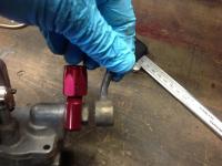
yes. ORB style. Has a washer seal.
-
Thread pitch on the drain plug is 8mm x 1.00mm.
-
Jeff, is what you are turning a flat plate or a round cylinder that is about 3/8" high? Sounds like the flat plate. There is supposed to be two parts/layers that are held together with a screw, guess you've lost that. There is a slot/hole to put a bolt/nut back on there so you have a reference Other than that, bubble gum, dab of JB weld, something anything that you can feel. Put a scratch/nick in it. paperclip, small cable tie, Ya! cable tie!, either style of adjustment knob, gives you a small permanent bump you can feel.
-
Jeff: Do you have the early knurled knob style or the flat plate scalloped edge style adjuster? The knurled knob has a little ball bearing embedded on the side that you can feel, and the scalloped one has a screw head on the underside that I use as a finger feeling reference. Turn them all the way in, note the rotation position of the ball/screw head relative to an imaginary clock face from the top, then spin away. As you turn past that starting position your brain will register that "aha! I've been here before" feeling.
-
First ID the source of the failure at bit. The + side of the coil needs +12 when you are cranking and running, so check it when running, and when failed. If you have +12 at the coil + terminal, then move to the "B" terminal on the ign module and check there. This checks the wiring between the coil + and "B". If no problem found, then you its not likely your wiring that supplies power to the coil. To confirm, hook up a jumper wire from battery + to coil + and see if it fires. If it does, take the jumper off and see if it still fires, maybe the "problem" cooled down and works now That's about all you check with a generic Volt meter. You can't see the signals on the - side with a voltmeter. Failure is likely either the ign module, coil (least likely if new) or the signal pickup coil in the dizzy itself. Take the module off the dizzy and remove the two little spade connectors that connect the module to the internal pickup coil. Check for good connection and dirty contacts. Clean and replace. Check, clean, re-crimp and continuity check all your wires from coil to module. If the failure is predictable, immediate, and repeatable (works fine after cool down everytime), my bet is on the ignition module too.
-
I think I'm siding with Stanley on this one, at least in the static case. He's not illustrating the effects that dynamic motion have on the system, he's showing static fuel level changes due to simple rotation. If you rotate about a point in the center of the carb, the jet tube physically rises (or falls) but the fuel level has to stay constant, so the fixed needle in the jet tube has to move away from or get closer to the fuel level! This is shown clearly in the drawing and I believe it represents reality. Remember the critical thing that affects how the car runs is where the fuel level contacts the needle, so carb rotation angle seems to be VERY important. The entire tuning process is trying to get that relationship correct. Technically you have to move the front and rear float fuel levels up and down to get back to a compensated average. But the more important question that comes to my mind is, why does a Z work well when driving up or down a steep hill if angle is so dang important? Well there is a very good reason. Here's where we move to the dynamic running case. The fuel does not sit a nice static level 10mm down the jet tube when the car is running. Fuel is being continuously drawn out through jet tube and is metered into the venturi by the diameter of the needle that is currently positioned at the jet tube top at the bridge, based on current demand. The float levels really don't matter at this point other than being in a spot that lets the bowls stay full, without the level getting too high. You still have to have fuel control to keep the static level BELOW the bridge or fuel will just pore out at low demand levels. The exact flow rate/mass profile of fuel in the jet tube during running is a complex thing. I'm pretty sure that how much the carb is rotated doesn't have that much affect on how the car runs as long as there is fuel supply below the top of the bridge. Until the car is upside down in the ditch that is.... At this is my take on it. Static float level/fuel level settings are one thing. Dynamic run time flow regimes are quite different. Longer tangs on the rear float bowl must have something to do with controlling the float motion or preventing it from binding in high angle situtations perhaps. Maybe someone took it up a steep hill and it quite running. Something that would be different in the back verses front due to the mirrow image configuration . I am pretty sure it was done for an engineering reason, not because the supplier screwed up and started supplying float bowl lids with longer tabs and they didn't want to waste them..... Ain't speculation fun.
-
Greetings from western Canada! I have probably 5 sets that came in generic gasket sets that I haven't used. How many would you like? That said, just hop over to Canadian Tire/napa/auto value and get some from felpro. Might have to by a head set to get them, but extra gaskets are always a good thing. There is a thread over on hybridz about valve seals that fit from other vehicles. Check there if you are doing anything other than stock. Drop me a line to z240@shaw.ca if you want mine.
-
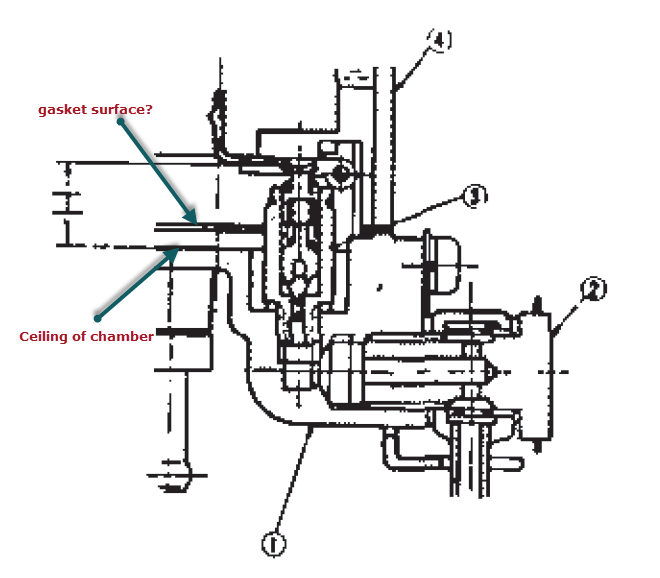
I think its natural for many to use the float bowl lid seam as the reference point, since you can actually see it, but the FSM (Engine Fuel, Fig EF-43 in the 71 FSM, picture in post #2) is pretty clear about it being 3mm above that at the ceiling of the lid. The diagram shown in post #1 has the reference I believe incorrectly showing at the lid seam. Why they would pick that spot is a mystery, maybe its because the reference for the static float measurement is from there too? Fig EF-44 is a bit hard to interpret, but I think it uses the same reference. I was reading in one of the old posts I studied recently about this that Bruce says its doesn't matter too much if the float level is perfect, you're just adjusting the jet tube height to match anyway. Within very small limits this is true, but we are trying to get the fuel level at idle to sit at a very specific spot on the needle. We don't have control of where the needle sits, its position is determined by the piston position which is vacuum determined. This is why Bruce and Blue and others have concentrated on seeing and setting the fuel level in the nozzle. This is the most important and accurate method, but hardest to actually do and judge, so the more practical (ok, lazy) of us tend to use the external methods with the site tubes. About the tang length difference, Bruce uses the term "It's out and out bafflement!!". http://www.classiczcars.com/forums/carburetor-systems-s30/45214-72-su-float-level.html post #14 I agree. Good thing it doesn't matter! Read on. What he does make clear is to set both carbs at 23mm fuel level no matter what. What is never clarified in any post is the upper reference point for that measurement. I'm sticking with the FSM for the moment and my top edge of retangular side-thing position. Other posts (looking at hybrid and zcar) mention the long ear vs short ear controversy. It is TRUE that you use different float level settings for the long verses short ears, but not different resulting fuel levels! I think this simple confusion of terms has lead to most of the confusion and angst about this subject. Float level setting are the lid-to-float measurement you make with the lid upside down or right side up, however you want to do that, and they vary from 13.5 to 16.5mm depending on the tang length you have, (see last post here su identification/ parts wanted - Fuel Delivery - HybridZ) and this is a good starting point, but the resulting fuel level in the bowls is what matters, and is ALWAYS the same target, 23mm. Put your floats whereever they need to be to accomplish the fuel level target. Now if only we had a way to ease the fuel level adjustment other than bending float tabs and all that goes with that process....
-
Hit the old "refresh" button, Jeff, 'F5'. I can see it fine in a couple of different browsers now.
-
There you go. Take that, you stupid computer.... Nope, now its gone again. Was there, really! Oh well, you got the point I guess And nice find there Dave at M-C! That place has 5 of EVERYTHING Is the attachment working for anyone else? I see it now!
-
working on it. Silly computers... Try to tell a good story, and you get this.. jeesshh
-
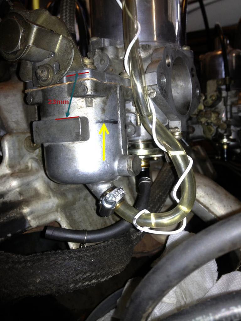
Well, I had to test a theory about correct fuel levels. If the correct measurement is 23mm, and its measured from the inside ceiling of the float bowl cover, not the gasket surface, then just where is 23mm down from there on the float bowl? Is there something on the float bowl or carb body that marks this critical position? Or are we doomed to use little rulers and sharpies and leave unsightly (un-site-glass-ly and shodily placed marks on our polished carb bodies? So I measured. And looked. Guess what I found. Taking a picture from Jarvo's post (#13) above, (I doodled a bit on it) What do you see? I see that magically 23mm down from the ceiling of the cover (the top of which is 3 mm up from the gasket surface), corresponds exactly to the very top edge of that retangular boss 'thing' on the side of the float bowl. Just what is that thing for anyway? I'm tempted to scribe my name in it, or mount a site glass in it.... and I see that Jarvo likely marked his 23mm measurement down from the float bowl cover gasket....
-
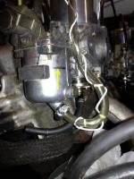
Perfect fit! SU banjo bolt + earls -6 banjo

-
Took one out tonight. 12x1.25 thread just like Mikuni! I'll bet that the earls mikuni bango works out of the box. 807691 I have a set here, I'll put one on a SU tomorrow and take a picture.
-
Earls has 12x 1.5 (weber) 12x1.25 (mikuni) 9/16x24 and 5/8x20 AN fittings/banjo's. Don't know what the SU threads are off hand. In case you can't find a commercial Earls banjo carb adapters with the right thread and length, you can make your own. The round fuel tube fitting that the stock SU banjo bolt fits through now, can be replaced with a flat chunk of aluminum stock of the same thickness. Make it (high/Wide) enough beyond the part where the bolt passes thru, so that you can tap an 1/8NPT hole into the end of it. Then get a common 1/8 NPT to -6 adapter fitting and screw that in. Presto. Just take a bit of flat bar cutting and grinding, nothing you can't do in the comfort of your living room. Google suggested there were SU banjo bolts out there, but none with the -6/-8 blocks to go with. Didn't look too far though. Never mind, here is the motherlode... http://www.anplumbing.com/Adapters/Banjos-26.html Maybe a Earls 977606 (bottom of the page) would be a direct fit using the SU banjo bolt and seal washers! wouldn't that be cool!
-
Must thread into the drain hole. Pretty nice piece. Overkill, but nice!
-
Vise grips to the rescue! Snatch onto the short "L" part of the clip that's sticking out, and with a small hammer on the vise grips while twisting, POP!
-
Congrats on your new baby! Beautiful color. It will be worth the effort. Don't forget to change them front wheel bearings too! Man, if ever there was a recipe for disaster (or embarrasment and ammunition for later), take your GF for a ride in an old car you just brought home. What were you thinkin', bro?