.JPG.cfcada9cf1c1b502df3f5f2f2ca3ff36.JPG)

SteveJ
Free Member
-
Joined
-
Last visited
Everything posted by SteveJ
-
 From the FSM on compression testing. Of course, you'll have to do it cold right now, but follow the rest. Note that the compression ratio will probably be lower with the engine cold, but there should not be a lot of variation in readings.
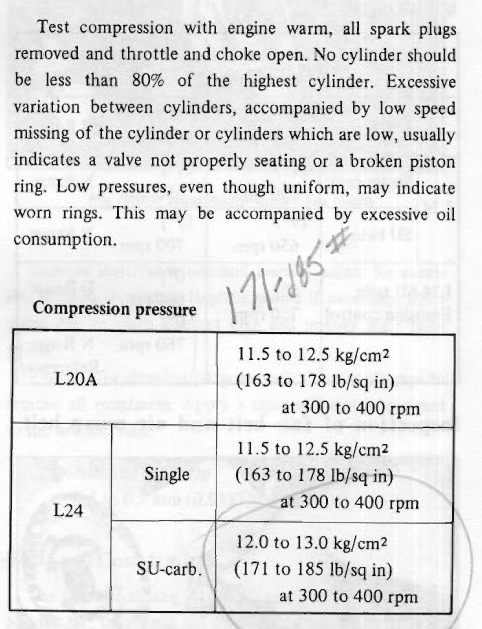
-
Use this stuff for starting. It's the cheapest you'll find.
-
Wow, how about shooting some video of you taking measurements just to make sure you're doing it right. Those measurements are way off.
-
Considering the engine was worked on, the readings seem low and all over the place. However, there can be variability in compression gauges. Also, technique is important. Make sure you look at what the ET section of the FSM says.
-
-
Here is a good tutorial on how to do the valve adjustment: https://web.archive.org/web/20080720024048/http://www.picturetrail.com/gallery/view?p=12&uid=786489&gid=1803105
-
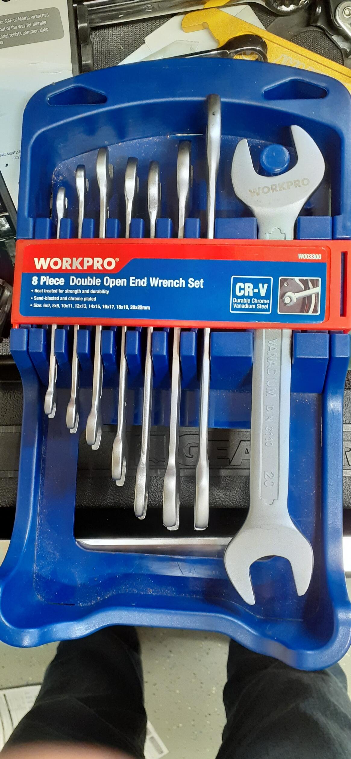
Lash pads are not the same as setting the valve lash. I can't speak to the technique to measure for the proper size lash pad, but maybe someone who does will chime in. This is the wrench set I like to use for adjusting the valve lash. They are not as thick as your typical wrenches, so it makes it easier to put both wrenches on the nuts for the valve adjustment. https://www.tme.com/us/en-us/details/wp-w003300we/wrenches-sets/workpro/w003300/

-
You measure valve lash with a feeler gauge. While there has been plenty of debate online about doing it hot or cold, you're definitely doing it cold. I hope your mechanic used properly sized lash pads. Use 0.008 for intake valves and 0.010 for exhaust valves.
-
If you still find them, Chevette springs can be cut to height. For some reason, there aren't a lot of choices available for a 40+ year old econobox. They give a much firmer ride, but I don't find them harsh or too stiff. The nice thing is that you can get 2 pairs of springs from Rockauto for $88 plus tax & shipping. The flip side is that you have to be willing to experiment to cut the springs the to right height. From re-reading the thread linked below, I guess I was aggressive with the amount I cut, but I'm happy with the results. I cut 3 from the rears and 2.75 from the fronts.
-
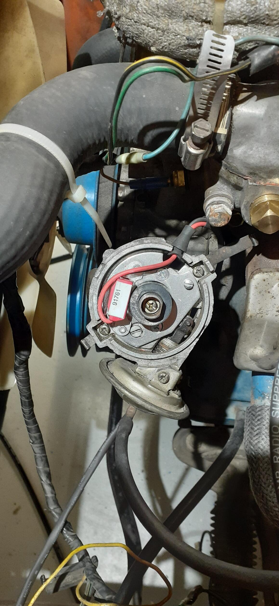
Pages BE-13 and BE-15 in the FSM cover these circuits. Common points of failure are the fuse box, the steering column connector connector where the green/blue and green/white wires pass between the dash harness and combo switch, and the combo switch. Unplug the steering column connector and check for voltage to ground at the green/blue wire on the dash harness side. It should always have battery voltage. Also examine the connector carefully for signs that it has overheated. I've seen many meltdowns at this connector. If you don't have voltage to ground, go back to the fuse box and test the voltage to ground on both sides of the fuse. The loose wires in the first photo are for the key buzzer. I'm not exactly sure where the second photo was taken, so I can't give an answer on those wires.
-
Where did you tap into for the voltmeter signal? There's a blue/red wire coming off the ignition switch and goes to the fuse box. It goes to the radio fuse coming out as a blue wire and the wiper fuse where it comes out as a blue/red wire. I'm guessing one of those wires, probably the blue wire is the signal for your voltmeter. If the blue/red is having intermittent contact to ground but not enough to blow the fuse, it could pull down the voltage on both circuits. Unfortunately you can't just pull the fuse for the wipers as that will also kill power for the reverse lamps.
-
It's the same part number in the parts catalog.
-
"Locking" means it is locking out the power switching circuit, so the coil never gets grounded. This is similar to why you don't want to leave the key in ON with the engine not running when you have points, only you are protecting other components.
-
And you can get them from a Nissan dealer, too, if you order part number 90522-E4100. https://www.courtesyparts.com/oem-parts/nissan-stopper-t-gate-90522e4100
-
Vintage connections has some good replacements for the connectors that use the spade style terminals. The round terminals for the gauges and dash harness to engine harness connectors were made by Yazaki (I think the spade connectors were, too.). Those connectors seem to be made of unobtanium, though you can get the terminals with different connectors from Eastern Beaver.
-
You don't have to go all redneck with spade lugs. You can get a replacement connector from Vintage Connections. But make sure you run the one test that I suggested. Have you looked at the C-5 connector?
-
To @Zed Head's point, you could take the black/blue wire off the ballast resistor, tape it up, and check the voltage again.
-
Is this what you're referring to? https://www.thezstore.com/page/TZS/PROD/34-1152
-
Then if your technique was good, that might indicate wear within the ignition switch. Did you order the full switch with key or just the module in the back of the switch?
-
And even when it's bad, it can be replaced by a GM HEI module pretty easily.
-
The switch contacts should be pretty close to zero. The resistance at the ballast resistor is fine. You don't want the resistance to be too high because that would be a voltage drop. It does appear that you are losing voltage somewhere, depending upon where you measured the 7.2V on the black/blue wire. Was it at the resistor or the ignition switch? Again, look for corrosion at the connectors for where the dash harness plugs into the ignition switch.
-
This sounds like a great time to shoot some video when trying to start so we can see what is and is not happening.
-
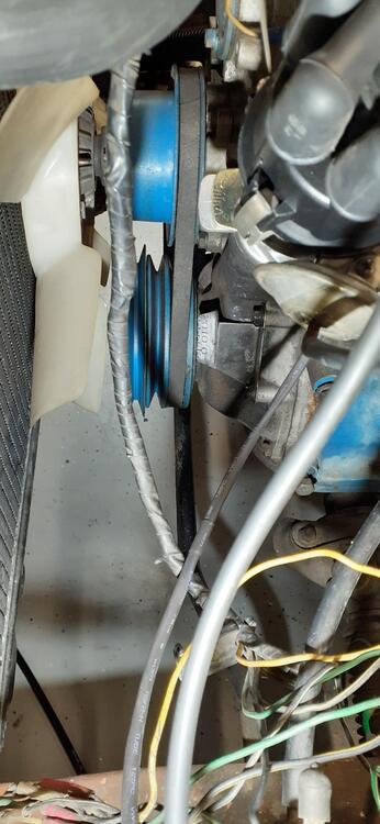
Overhead shot of the magnet placement

-
Sorry, I didn't mean to confuse. This thread may help some.
-
Maybe this will help. This is the timing mark on the 240Z with the distributor as reference.