.JPG.cfcada9cf1c1b502df3f5f2f2ca3ff36.JPG)

SteveJ
Free Member
-
Joined
-
Last visited
Everything posted by SteveJ
-
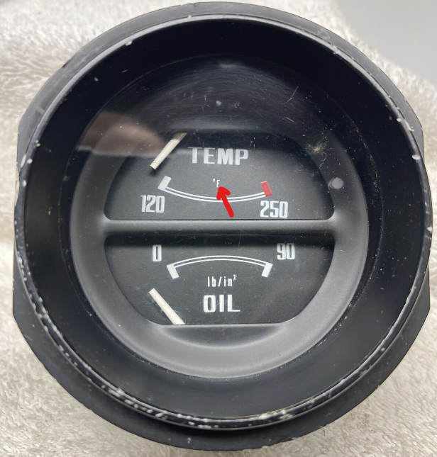
 Don't forget about cleaning the connections on the fusible links, too. Dang, that's LOW oil pressure.
 -
-
-
In the first photo, you can see the fan is blurred, so the car is running. Unless @240zadmirehad not tried to rev the engine to excite the alternator before that photo, the voltage is low. Since the alternator and battery are connected, you should see the same voltage at both. The only thing that would drop the voltage at the battery is corrosion.
-
-
Also, don't use teflon tape on the threads. If you do, you'll likely insulate the stock sender from the block.
-
That voltage is on the low side. It should really be reading around 14 above 2000 RPM. I suggested the cigarette lighter voltmeter because it's easy to compare it to the voltmeter in a 280Z and know what the voltage is while you're driving around.
-
Here are links for parts/pieces/tools that may be useful for addressing issues brought up in this thread. Verifying the voltmeter: https://www.amazon.com/dp/B01M9IKYVH Plug it into the cigarette lighter (provided it works). These things are handy to have. Verifying the oil pressure: Adapter that allows a mechanical gauge to be added: https://www.glowshiftdirect.com/1-8-bspt-male-to-1-8-27-npt-female-hex-thread-adapter/ Mechanical oil pressure gauge: https://www.amazon.com/Equus-5244-Mechanical-Pressure-Gauge/dp/B0747VR5WX Verifying the temperature: https://www.harborfreight.com/121-infrared-laser-thermometer-63985.html I haven't seen anything wrong with water temp. I'm not sure the fan clutch kicking in is a problem unless it keeps the engine too cool.
-
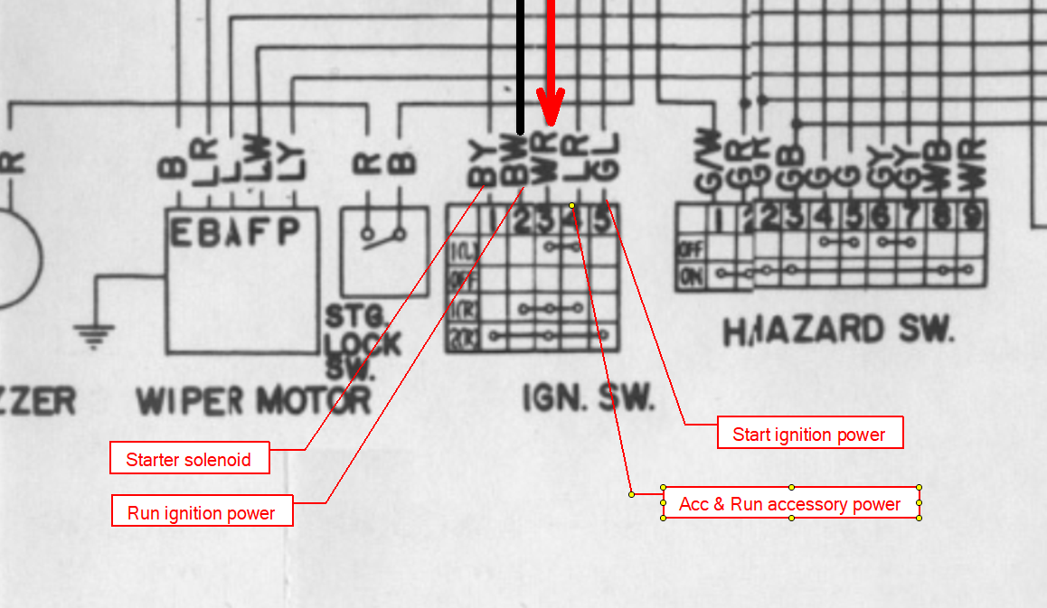
There aren't any spares on the ignition switch. The GW wire at the ballast resistor would have 12VDC+ during starting. You can back the pin out of the engine harness side of the connector to prevent shorting. Alternatively, if you need the Haltech powered while starting, do the following: In the engine bay, replace the connectors for the BW (Ignition switch one, not the coil positive one) and GW wires to a male/female insulated set and plug them into each other. Use the GW wire at the tach to run to an inline fuse and on to the Haltech. Since I have never played with the Haltech, I cannot tell you whether or not this is beneficial.

-
I have some ABS rod on order, too. The first materials are just to get my technique going, such as drilling out the rod for the spring. As for the lathe, I was planning on using the drill press. It's the cutting tools that I need to figure out.
-
I would not recommend the defroster circuit for the Haltech. It's hard for me to say anything about the GW wire since I don't have detailed photos of your engine bay to see how things are connected now. All I can say is that the way I suggested is safer because you won't have a 12VDC+ wire hanging out in your engine bay doing nothing but waiting for a short circuit to happen. (I don't like abandoned wires that could be hot.)
-
-
I should get some acrylic rods to experiment with tomorrow to see if I can develop some techniques with what I have on hand. I know that I encounter melted nubs when I help people with the switches.
-
Agreed. Assuming a linear response in the gauge, I wouldn't worry unless the needle was clearly to the right of F and staying there. As for the oil pressure, I know I've linked the parts a couple of times now for putting an adapter and mechanical pressure gauge on the engine to allow both gauges to function.
-
But there is an F on the temperature gauge.
-
-
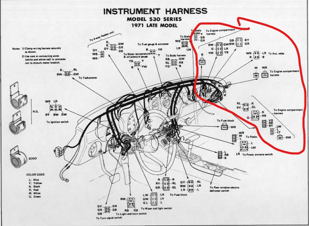
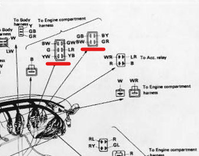
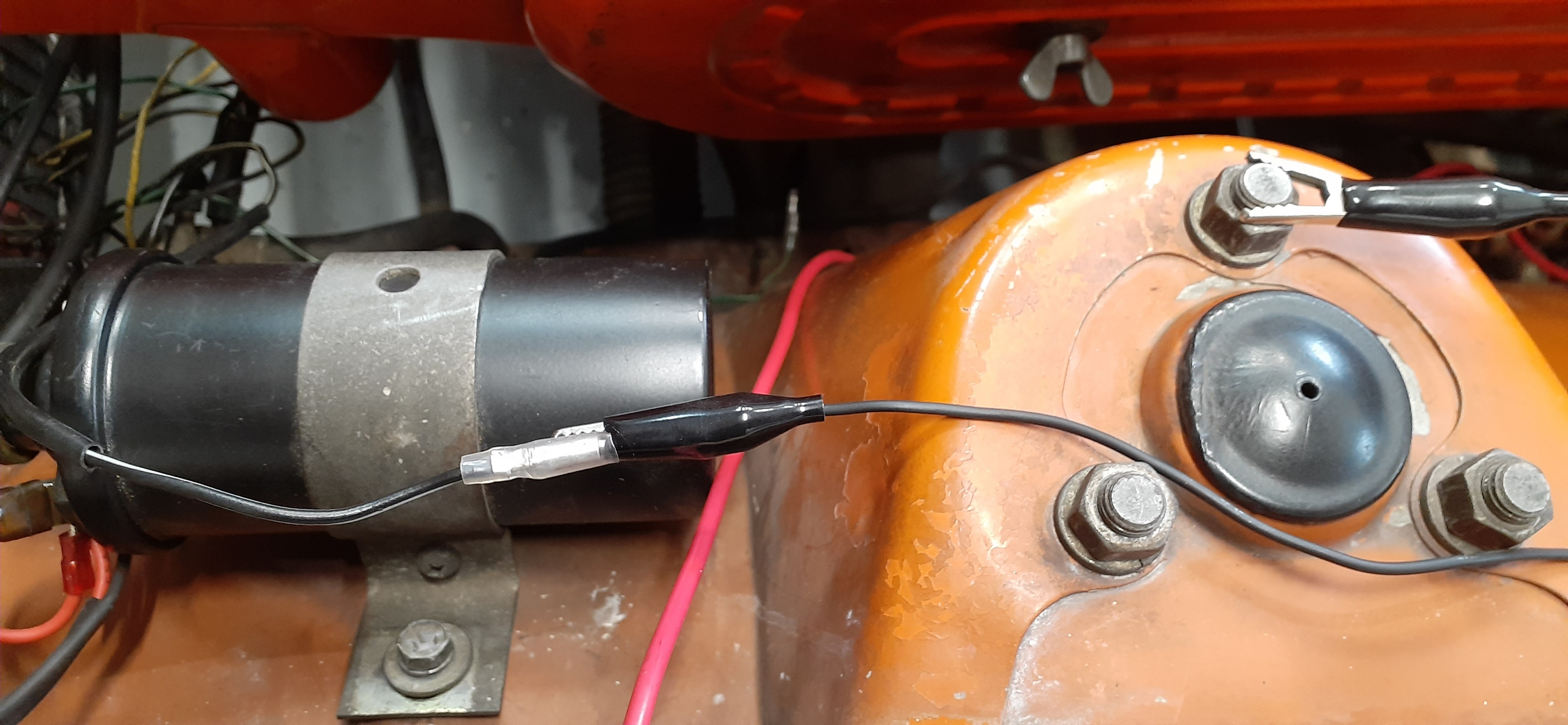
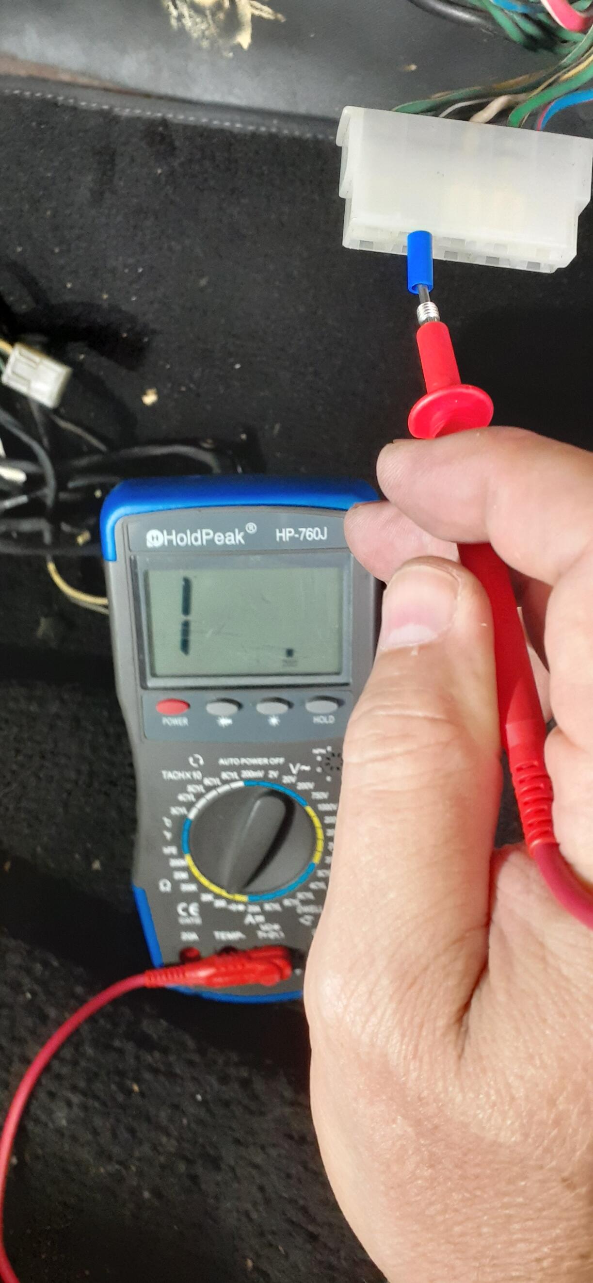
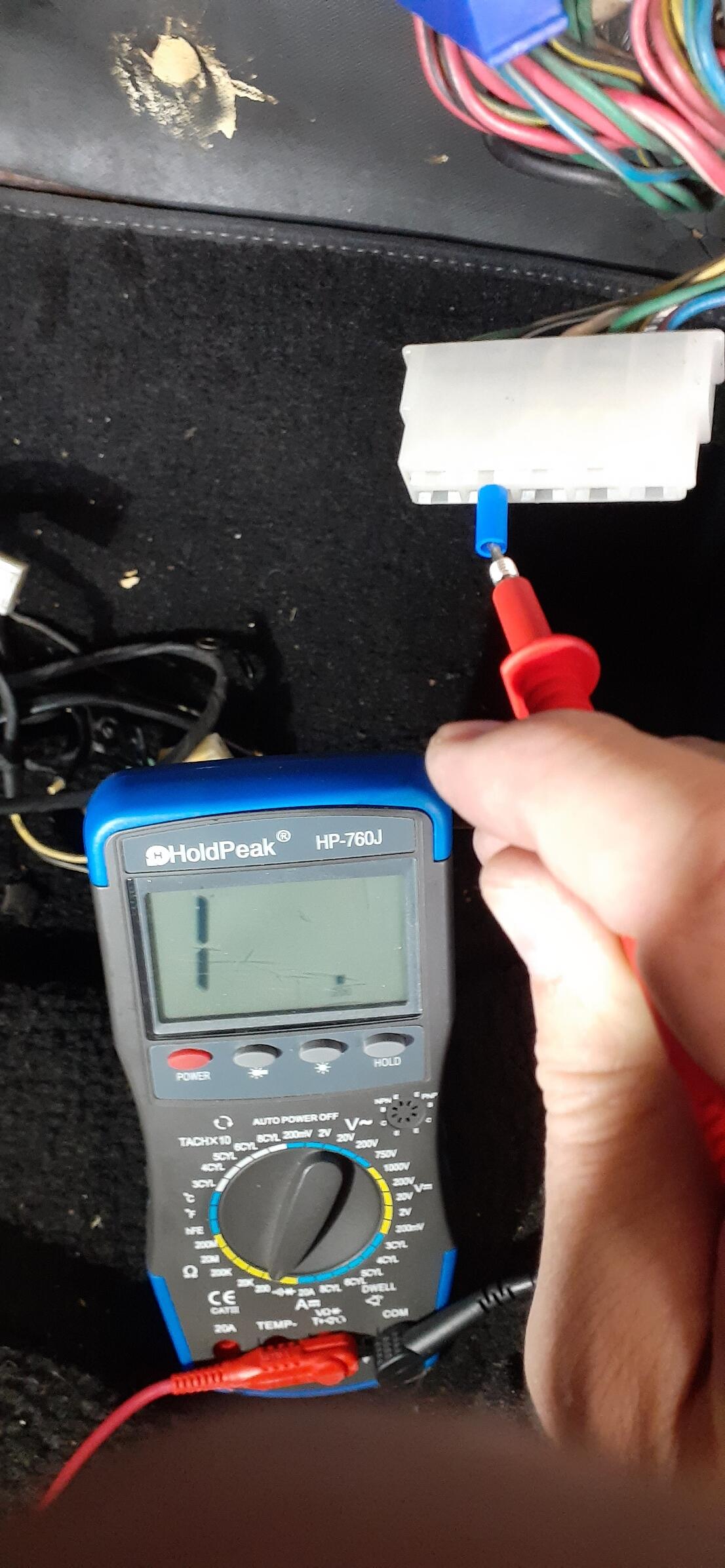
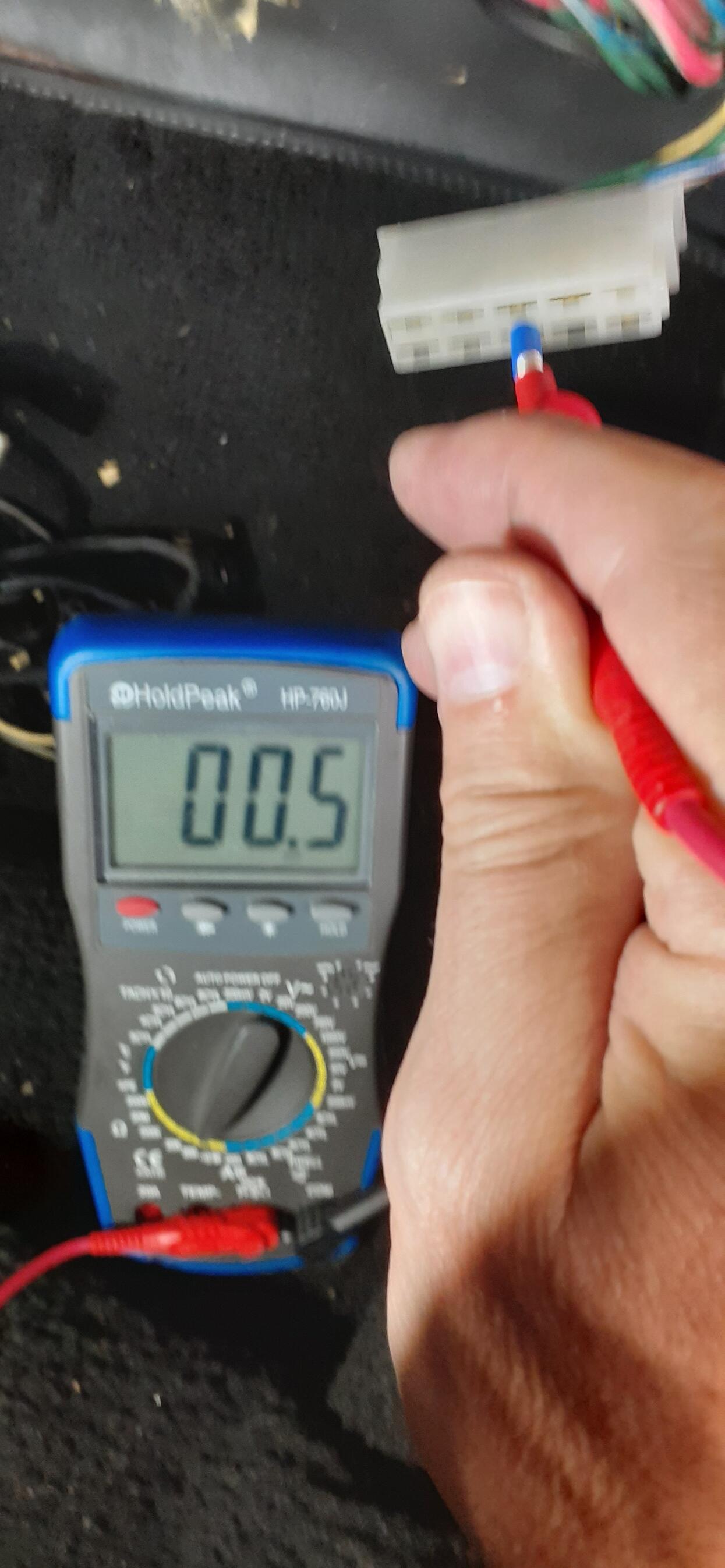
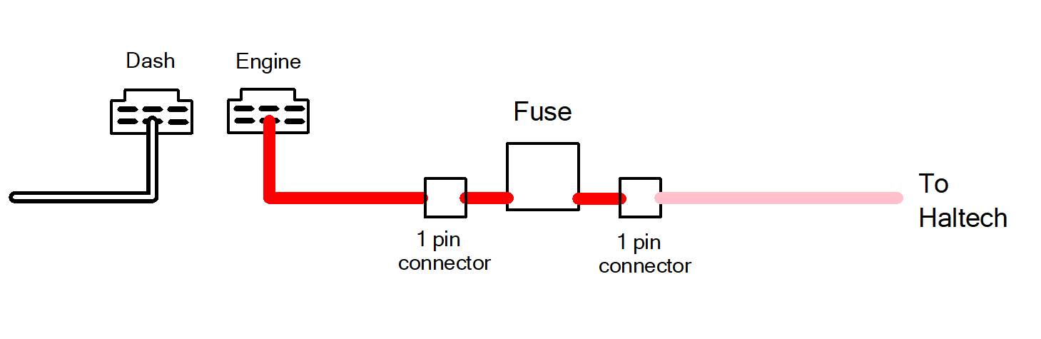
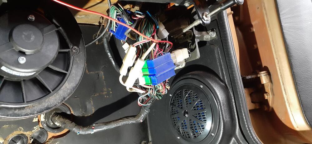
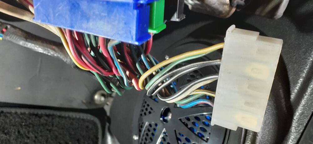
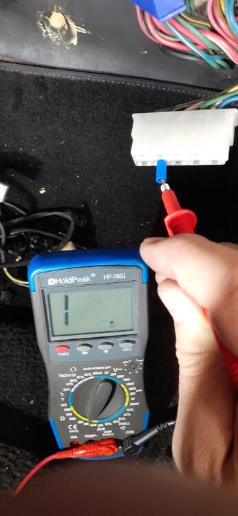
Going back to my detailed instructions, here is how you find the wire I suggest you use. First locate the wire junction in the passenger footwell. (Mine looks different because it's a 73.) Find the connector(s) that have BW wires. When you find it (them), disconnect the engine side from the dash side. (You can see the engine harness going through the firewall. Make sure the BW wire is disconnected from the ballast resistor and use a clip lead to ground it to the shock tower. (I have a bullet connector on the BW in my car due to modifications I made.) Ground the black lead on your meter. Take a spade lug and plug it into the connector where there is a BW wire. Check resistance. If you aren't seeing low resistance, (My meter is displaying the 1 well to the left of the decimal to indicate "open line") move the spade lug to another BW wire and test again. Eventually you should find the correct wire. (It's a little blurry, but I hope you get my point.) You can back out that pin and create the circuit I described earlier. The reason for the short piece of wire and connector before the inline fuse is in case you ever need to pull the engine wiring harness, you can still pull it through the hole in the firewall just by disconnecting between that wire and the inline fuse. This is how the circuit would look as I described it earlier. I just selected a random pin on a six pin connector to represent what you might see. The actual pin location may be different. You can just leave the old BW wire that went to the Engine Harness connector dangling if you want. It's dead. Is this more work than what you proposed? Certainly, but with this there is little risk to the wiring harness or Haltech wiring.


-
You said before you are driving the tach from the coil on plug. That is the signal, but the tach needs 12VDC to power the discrete components to read the signal, unless you have another wire from the Haltech providing 12VDC switched to the tach. I suggest you consider my solution detailed earlier rather than splice into the harness. It's more work the way I suggested, but there is sound reason behind it.
-
Easy solution for the parking lights - LEDs all around (gauges, front markers, rear markers, and side markers)! It might even keep the connector at the steering wheel from melting.
-
What? You don't want to try casting?
-
-
Yes, I'm out of my mind. Is that important? With a lathe, there is less chance of burning something/catching something on fire. Where's the fun? Now with molten metal, opportunities abound! Seriously, I might just buy the delrin rod.
-
By removing the BW wire from the ignition switch, you also remove power from the following: Tachometer positive Turn signals Voltage regulator (If you did the internally regulated alternator swap, this is used as the switched source for the alternator.) You'll either need to use a Haltech switched source and find a place to connect into the wiring (Please don't hack the wiring.) or take a path like my directions.
-
I would think that friction resistance is probably most of the reason. Also the parts supplier may have had access to injection molding equipment that would allow them to knock off a bunch of the plastic parts as opposed to machining the metal bits. (Dang it, now you have me thinking about the possibility of casting with brass. You are evil, @Captain Obvious!) I am tempted to see about getting a 4mm delrin rod to play with to see if I could make the plastic part.
-
It is the BW wire. However, if Duffy connects the pink wire at that point, there is no protection for the wiring. That's why my instructions are as detailed as they are. Mind you, I do controls engineering for emergency power, so I do look at how to prevent the magic smoke from escaping from the wires.