


.JPG.cfcada9cf1c1b502df3f5f2f2ca3ff36.JPG)

SteveJ
Free Member
-
Joined
-
Last visited
Everything posted by SteveJ
-
 Try blowing the line out from the front with compressed air. Have someone take off the gas cap and listen for the air coming out. You could have stirred up junk in the tank and clogged the line.
 -
I have some that may be in decent shape. They would need to be painted, though.
-
I bought a few of these to play around with. https://www.amazon.com/dp/B09VK1WYVP I found the harness to plug into it on Aliexpress and bought a few, too.
-
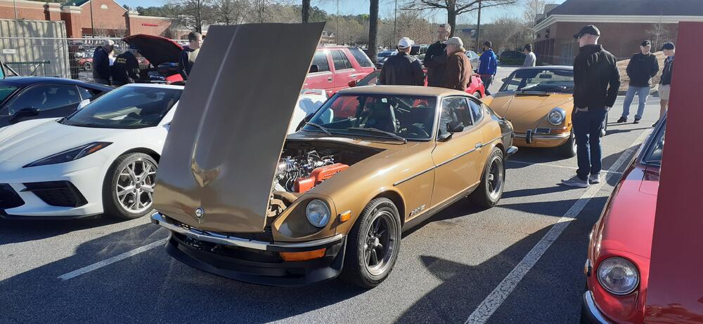
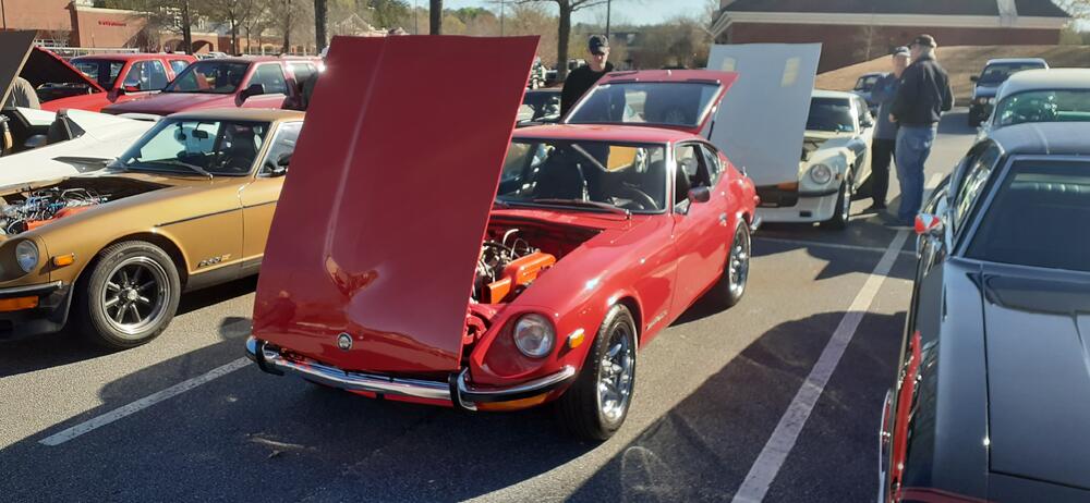
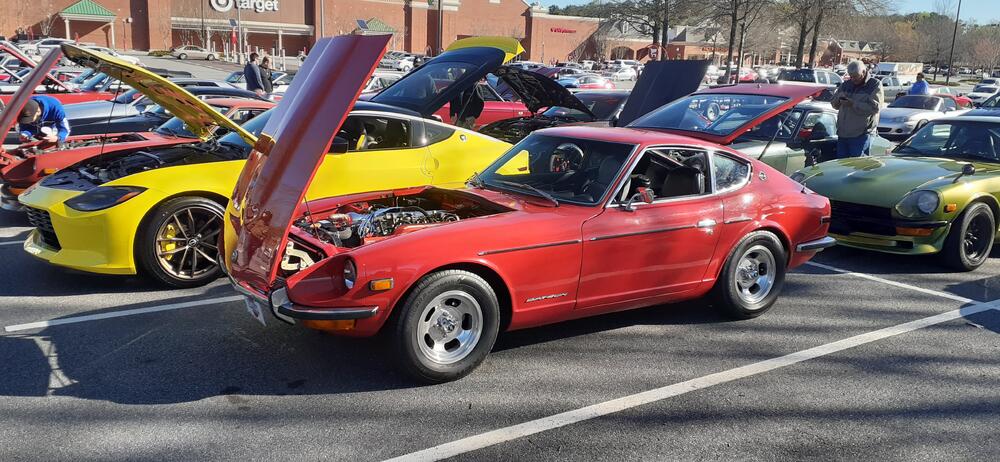
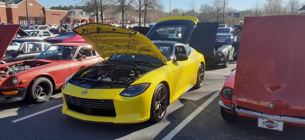
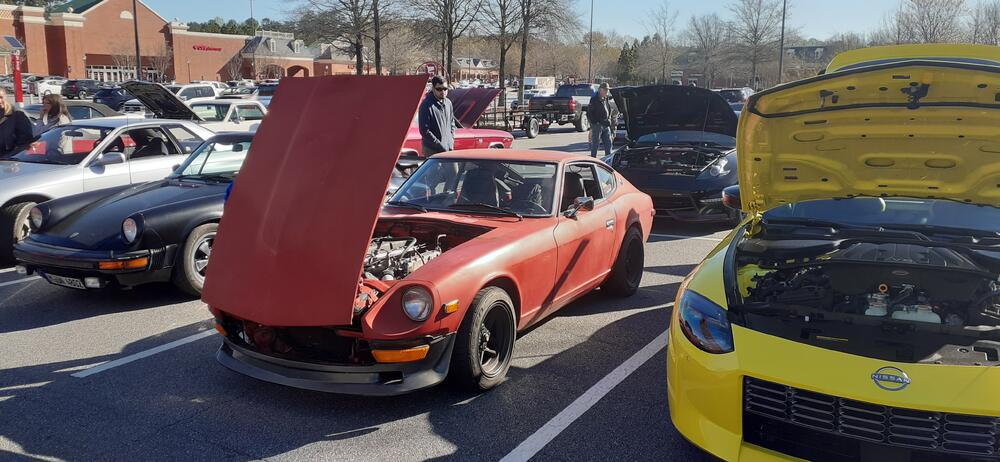
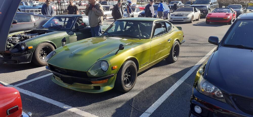
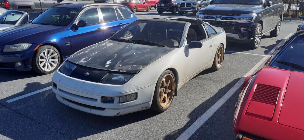
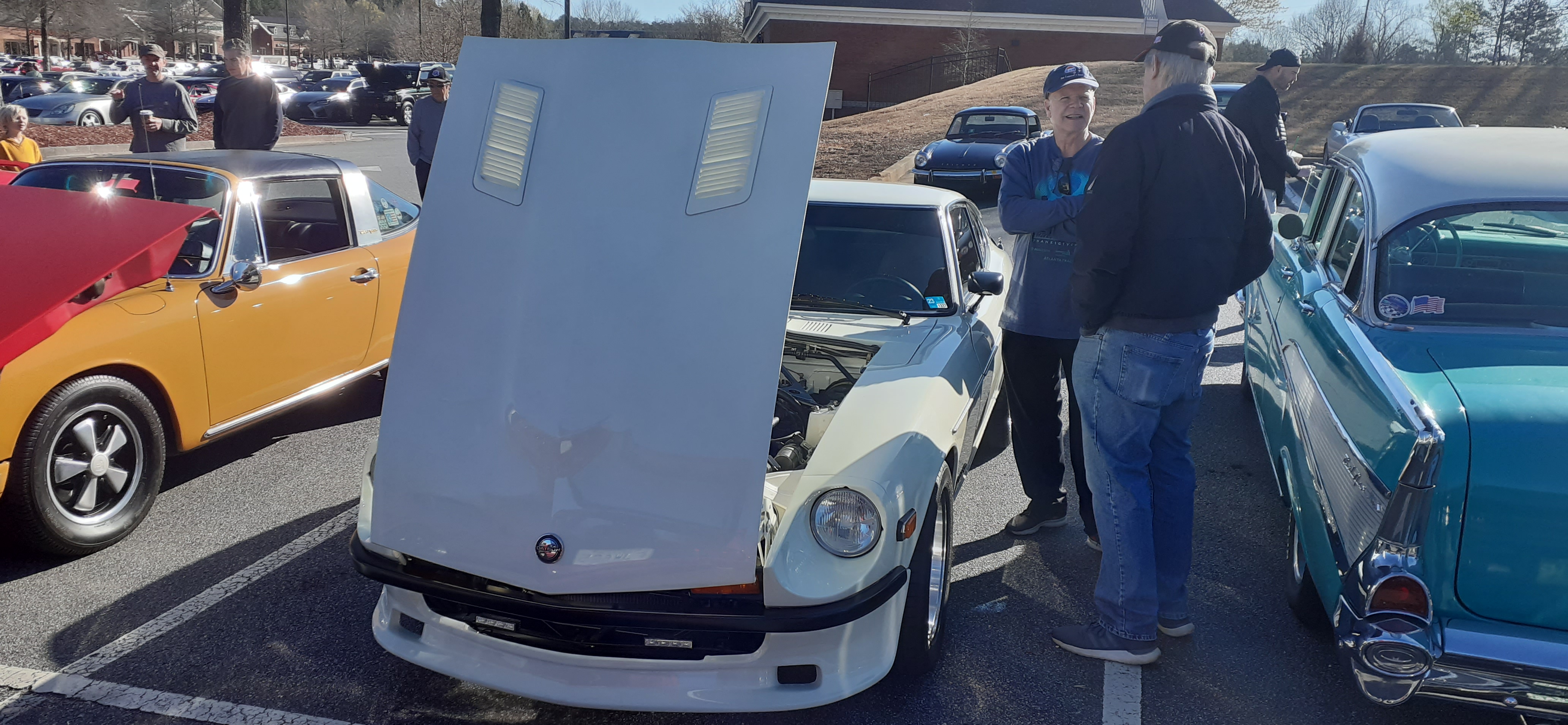
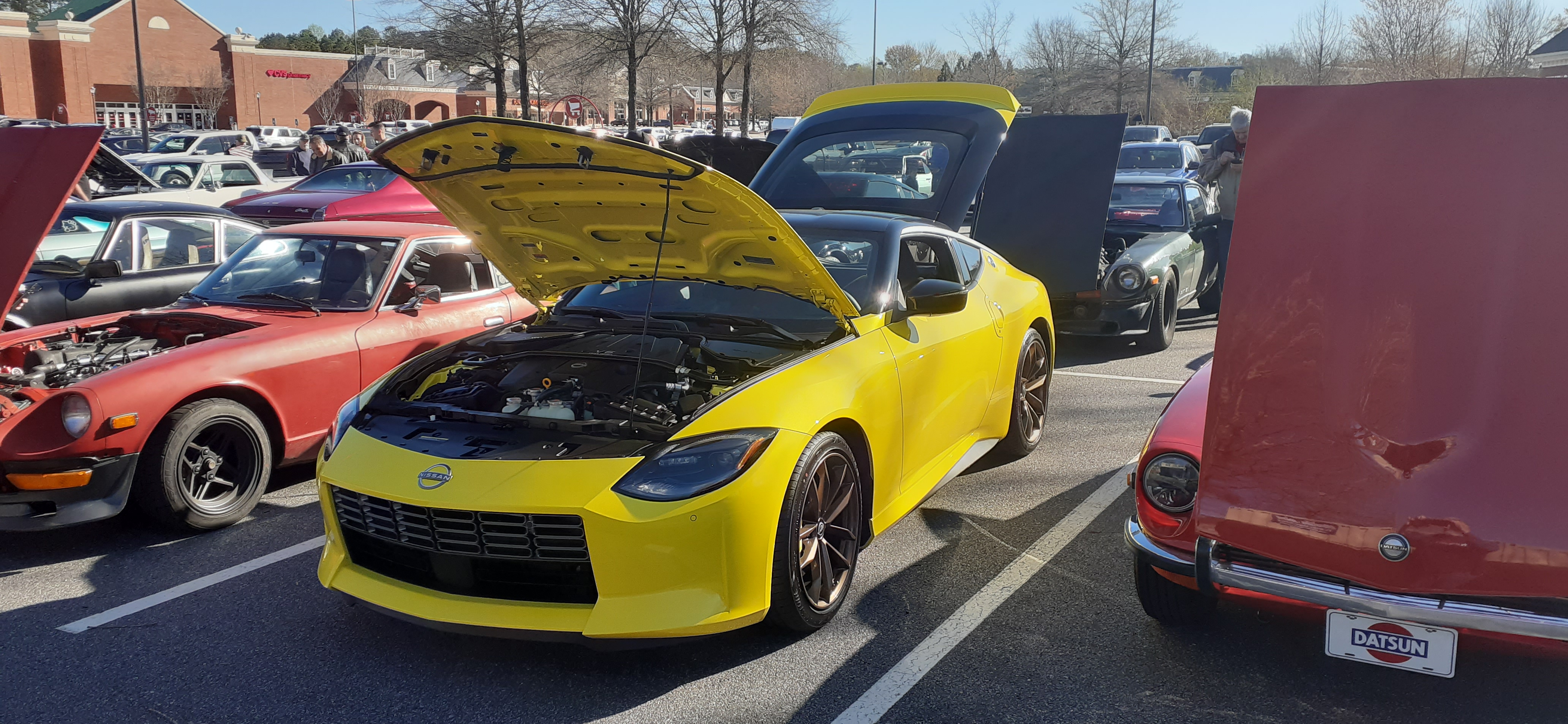
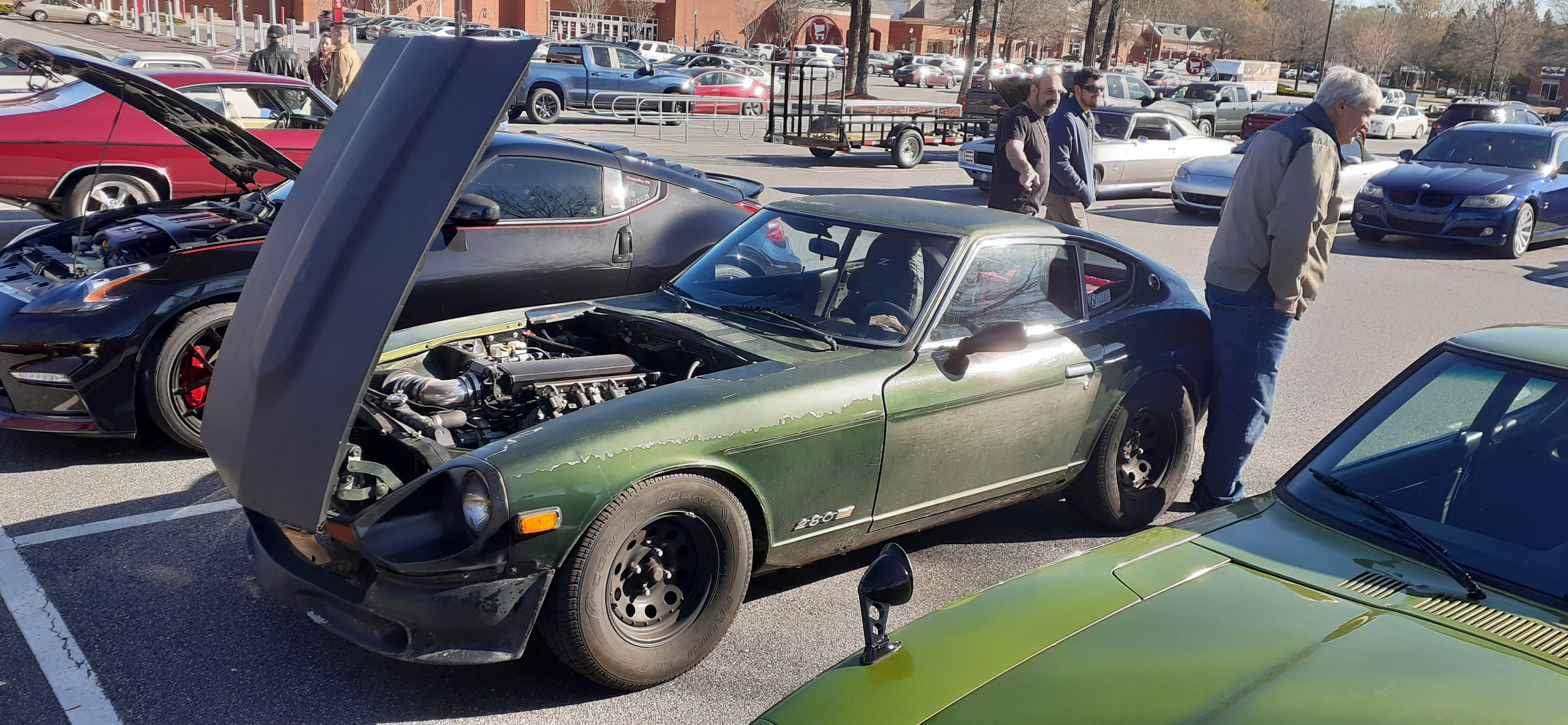
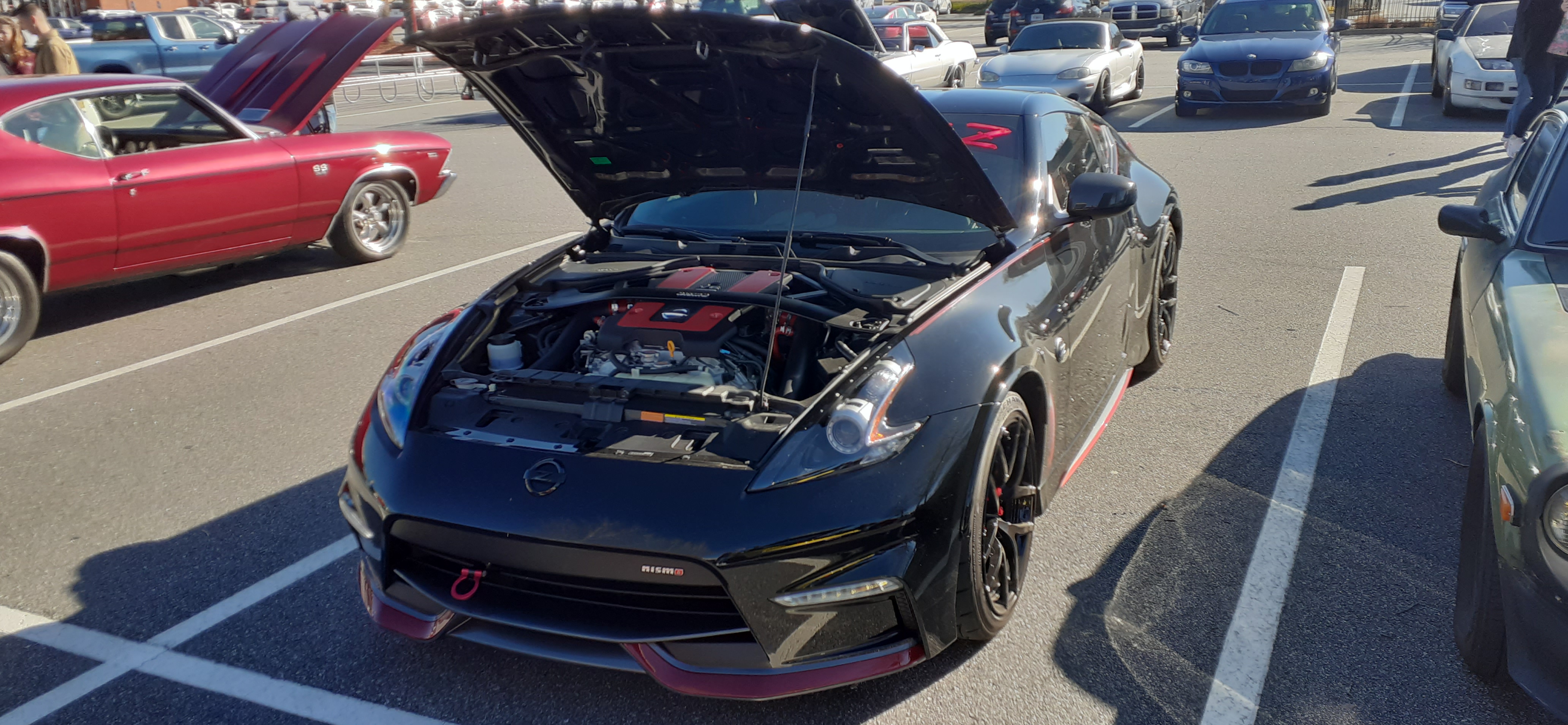
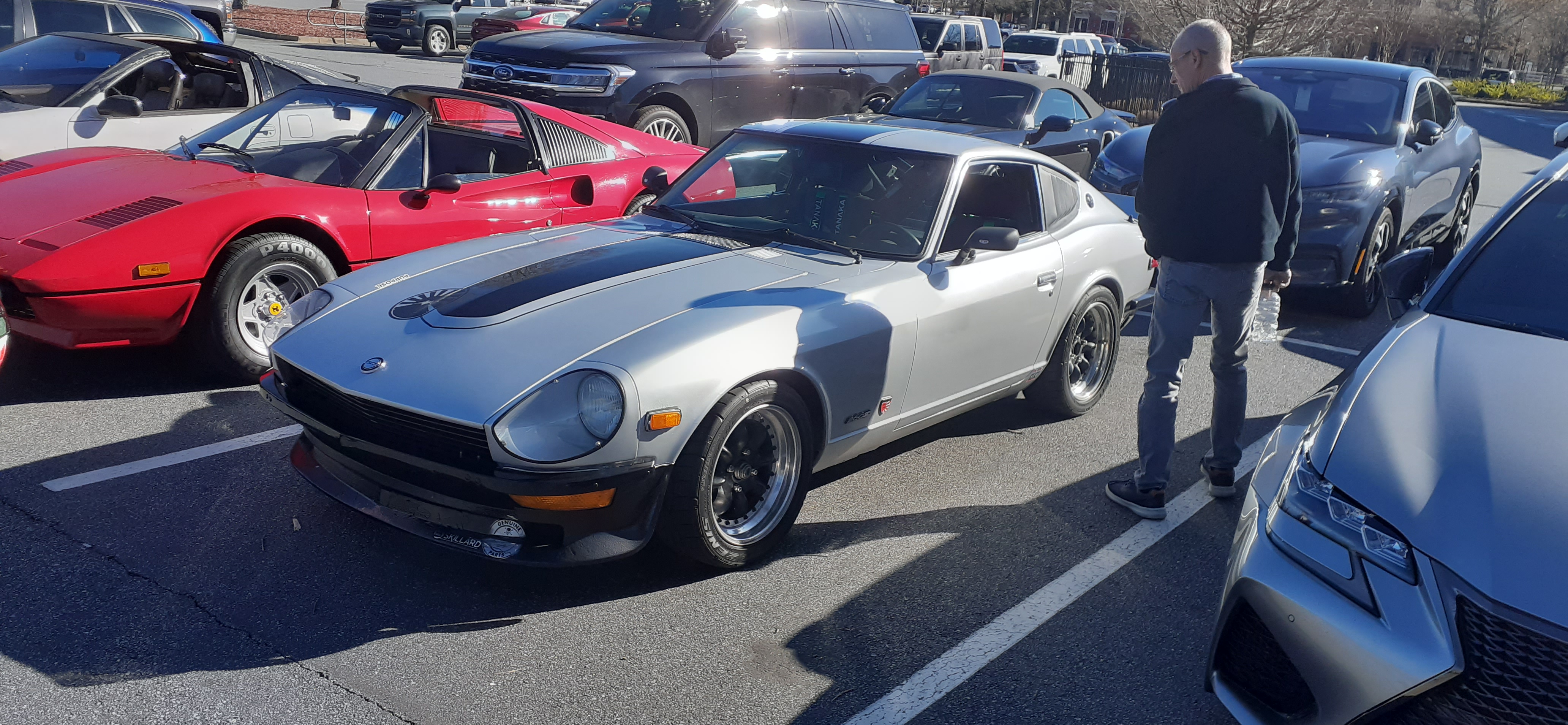
The first Sunday of the month and another early morning car meet. Great weather led to a great turnout.


-
The condenser at the distributor was to help reduce the voltage spikes on the points. The ZX distributor doesn't have points, hence the lack of a need for the condenser. The one at the alternator is to reduce noise for things like your radio. I'm not sure about what condenser you're talking about for the other components. Where do you see this?
-
I actually made a video on that subject to help people who get confused when they disconnect the wires from their ballast resistor and coil. I have been using the ZX alternator for over 20 years, and the GM "one wire" operates pretty much the same way. As far as relays go, you may want to read this: https://fiddlingwithzcars.wordpress.com/2012/12/22/relays-simplified/
-
Let me re-phrase. The 85 pin on the relay would come off a fuse fed by the black/white ignition wire. The 86 pin would be grounded. The 87 pin would be a constant voltage source, and the 30 pin would run up to the lamp light on the voltmeter. The other wire on the lamp light would run out to the L terminal (switched) on the alternator.
-
Here's my 2¢ on this. When I'm looking at fixing my engine harness, I'm thinking of using a relay controlled by the ignition power and having a constant voltage source that goes out to the L terminal of the alternator. This would eliminate the feedback on the ignition circuit that drives people to add the relay. As for the diode and lamp being in the same circuit, resistance is a non-issue. Diodes don't have appreciable resistance. You will need keep the voltage lamp as an incandescent, though. That way if you start to see a glow in the lamp, you know the alternator is starting to fail.
-
If you wanted to go simple, you could go with a system similar to what Rick Patton sells. It limits tunability, but it is simple. Affordable Fuel Injection sells the repurposed ECUs. The parts to support it are easily sourced. Another possibility is Megasquirt. You would have to set up a base map. This link gives you an idea of what you need to do: https://www.diyautotune.com/news/tuning-tips/megasquirt-efi-tuning-ecu-jeff-linfert/
-
And it's NLA. That's no big surprise.

-
Plug and pray
-
And Jay Ataka @esprist also was just featured on Jay Leno's Garage.
-
The photos look familiar...https://www.zcar.com/threads/wiring-ignition-with-rebello-carbureted-l28-into-a-77-280z.424085 Are you sure you trust that joker who told you what to do.
This is where an oscilloscope comes in handy. One channel has an inductive lead on the #1 plug, and the second channel is looking for the signal from the distributor.
You didn't have to Google it. I gave you the link to look it up.
Prompted by @Zed Head's reply, I looked at the Autozone site again. The sample pictures match the reman Hitachi, too. It also has the N and F terminals that I would expect. It's good to know that my mind isn't completely gone. I'm glad Zed also remembered the P terminal. By the way, here's a link to a list of alternator terminal designations: https://shop.pkys.com/Alternator-Terminals-explained.html
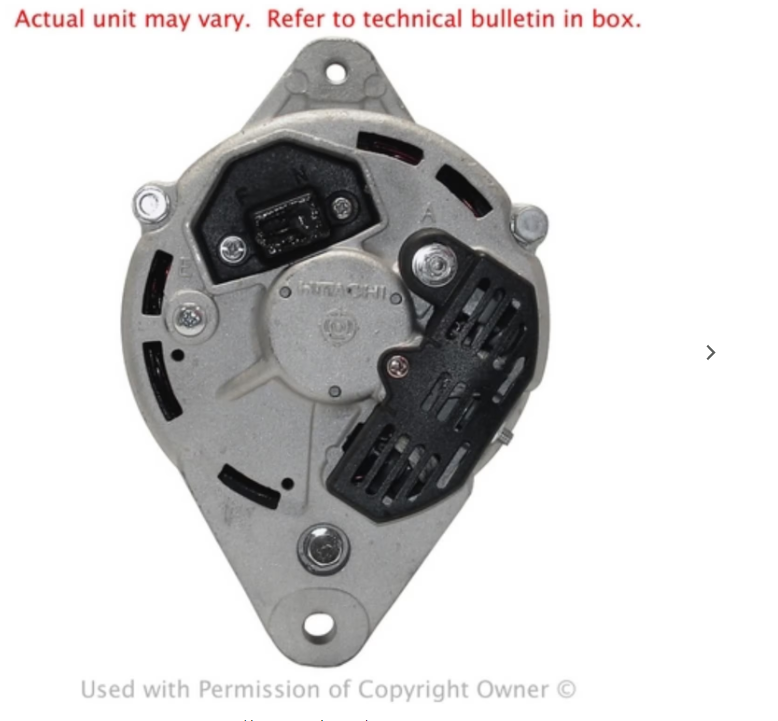 The cross reference would make one think it's externally regulated, but there is usually an N and F by the T plug for neutral and field IIRC. Just monitor the voltage, and if it's above 15 VDC to ground, it's internally regulated.
The condenser is supposed to be grounded like how you received it. It looks like you opted for the internally regulated alternator. You'll need to look at Blue's tech tips on how to jumper the wires on the voltage regulator to give it the signals it needs.
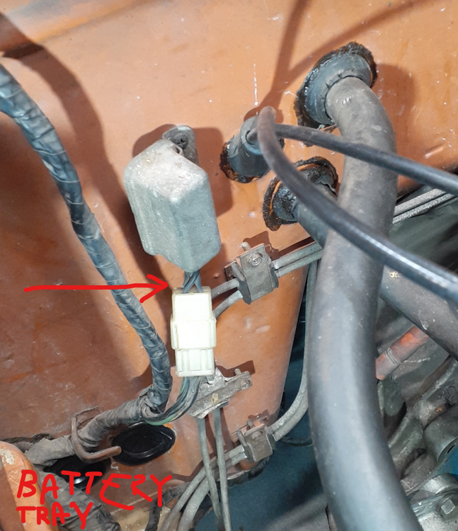
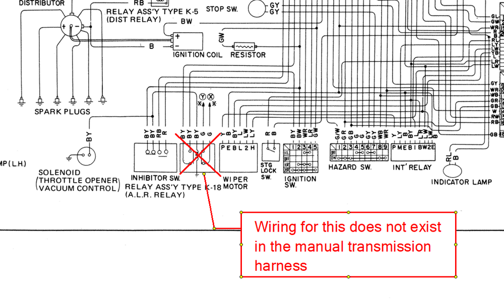
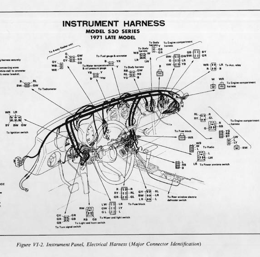
I knew I had looked at this before. That connector resides here Here it is in the wiring diagram. While it's on the passenger side firewall, the diagram has it by the coil. It hints that the BW wire spits before the 4 pin connector, but I'm not sure we can believe that. The BY wire would go from the passenger firewall, around the front of the engine, and over to the intake. The GB wire changes color somewhere and goes to the relay on the speedometer where it gets grounded. I think you and I discussed that in emails. The "green" wire in the wiring diagram changes color before that connector, too.
The cross reference would make one think it's externally regulated, but there is usually an N and F by the T plug for neutral and field IIRC. Just monitor the voltage, and if it's above 15 VDC to ground, it's internally regulated.
The condenser is supposed to be grounded like how you received it. It looks like you opted for the internally regulated alternator. You'll need to look at Blue's tech tips on how to jumper the wires on the voltage regulator to give it the signals it needs.
I knew I had looked at this before. That connector resides here Here it is in the wiring diagram. While it's on the passenger side firewall, the diagram has it by the coil. It hints that the BW wire spits before the 4 pin connector, but I'm not sure we can believe that. The BY wire would go from the passenger firewall, around the front of the engine, and over to the intake. The GB wire changes color somewhere and goes to the relay on the speedometer where it gets grounded. I think you and I discussed that in emails. The "green" wire in the wiring diagram changes color before that connector, too.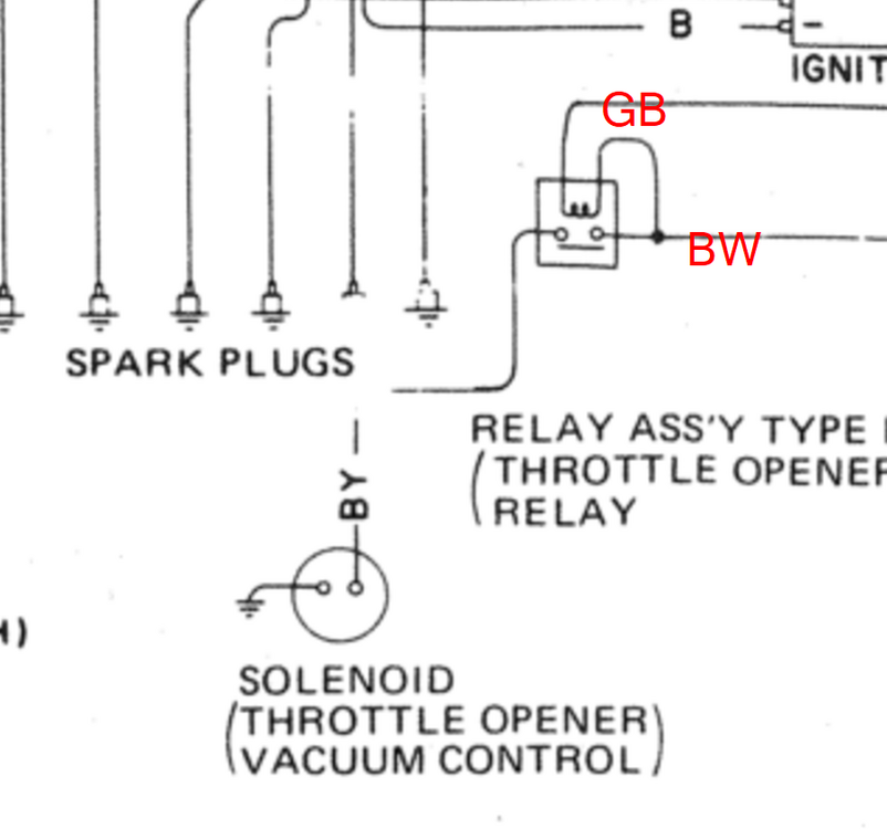
 So the connector you're talking about is on the engine harness. My "spare" isn't in a decent condition to analyze. I may be able to see it in my car. I'll try to remember, but it may take some gentle nudging.
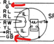
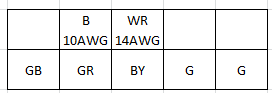
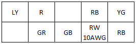
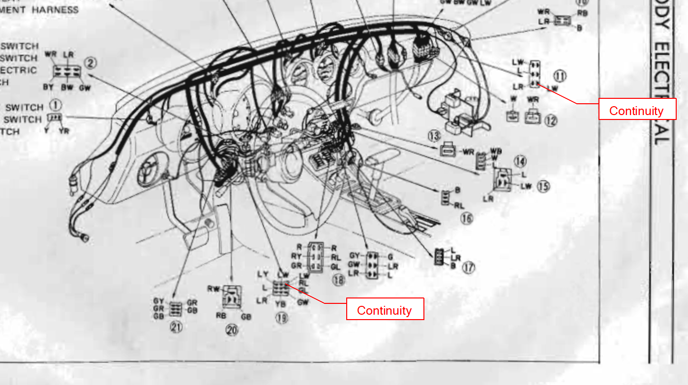
On my spare dash harness, it's another case of the FSM not matching. Looking at the back side of the connector, here is the wiring: The green wires are probably for the seat belt buzzers. The seat belt relay does not exist in the manual. The green wires go to the neutral switch on the transmission. I think when the car is in gear, the neutral switch completes the circuit to go to the buzzer and seat belt light if you don't have the belts fastened in occupied seats. (Be sure to buckle in your groceries if you put them in the passenger seat.) I think you and I discussed the throttle opener in a private message. In the engine bay, the BW wire splits to go to both BW terminals on connector 18. The BY goes to the throttle opener solenoid, and GB goes to the speedometer. So for this one, the LY wire is NOT LY. It is LW. I used a meter on my spare harness to find where it goes. It's part of the wiper circuit, going to the 9 pin connector at the steering column and the 6 pin connector at the intermittent relay. Here is the layout of the blue connector on my harness:
So the connector you're talking about is on the engine harness. My "spare" isn't in a decent condition to analyze. I may be able to see it in my car. I'll try to remember, but it may take some gentle nudging.
On my spare dash harness, it's another case of the FSM not matching. Looking at the back side of the connector, here is the wiring: The green wires are probably for the seat belt buzzers. The seat belt relay does not exist in the manual. The green wires go to the neutral switch on the transmission. I think when the car is in gear, the neutral switch completes the circuit to go to the buzzer and seat belt light if you don't have the belts fastened in occupied seats. (Be sure to buckle in your groceries if you put them in the passenger seat.) I think you and I discussed the throttle opener in a private message. In the engine bay, the BW wire splits to go to both BW terminals on connector 18. The BY goes to the throttle opener solenoid, and GB goes to the speedometer. So for this one, the LY wire is NOT LY. It is LW. I used a meter on my spare harness to find where it goes. It's part of the wiper circuit, going to the 9 pin connector at the steering column and the 6 pin connector at the intermittent relay. Here is the layout of the blue connector on my harness:
 The other inline fuse is for the radio. The one with red wire is for the fan.
The inline fuse holder is for your fan. The larger three wire connector is for the antenna. The three wire stacked connector is for the radio. Black is typically ground.
The other inline fuse is for the radio. The one with red wire is for the fan.
The inline fuse holder is for your fan. The larger three wire connector is for the antenna. The three wire stacked connector is for the radio. Black is typically ground. Do you actually have an aftermarket AC, or are you calling the fan AC? Unless you have a JDM car, you don't have stock AC. Always supply the wire colors going to a connector. That helps to identify it more easily. As for the wire you're holding, that isn't a typical lug for Nissan wiring, and brown/white isn't a 240Z wire color.


Important Information
By using this site, you agree to our Privacy Policy and Guidelines. We have placed cookies on your device to help make this website better. You can adjust your cookie settings, otherwise we'll assume you're okay to continue.