
Electrin97
Community Member
-
Joined
-
Last visited
Everything posted by Electrin97
-
Clears the hood no problem! I thought about fully polishing one but I didnt want to commit to all that sanding 😂
-
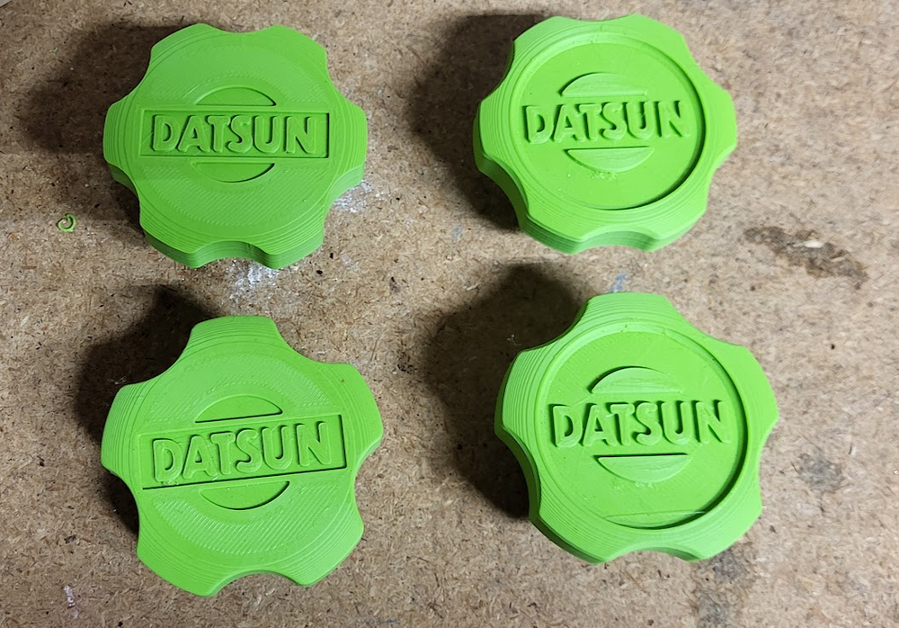
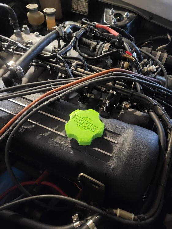
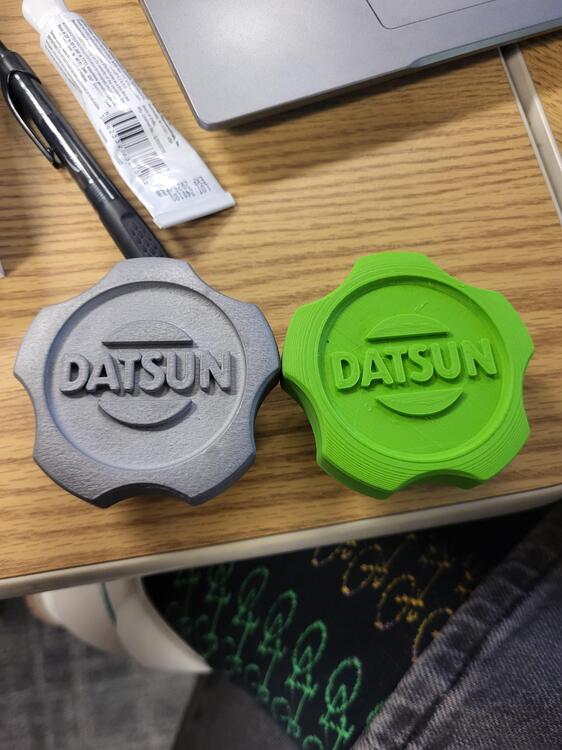
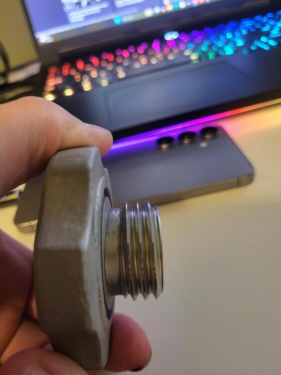
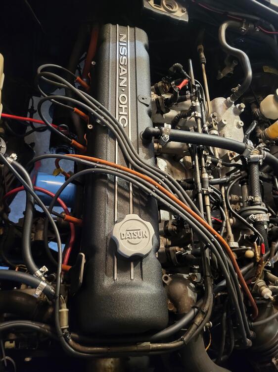
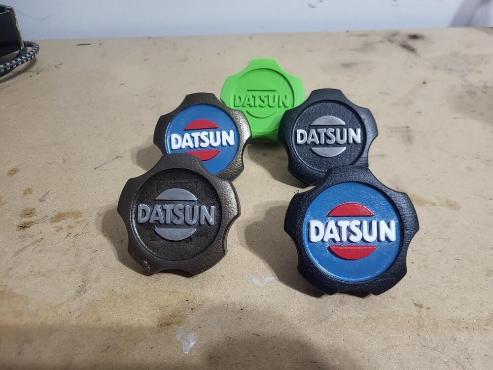
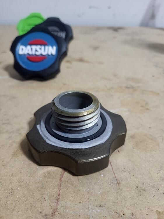
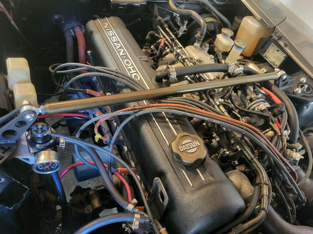
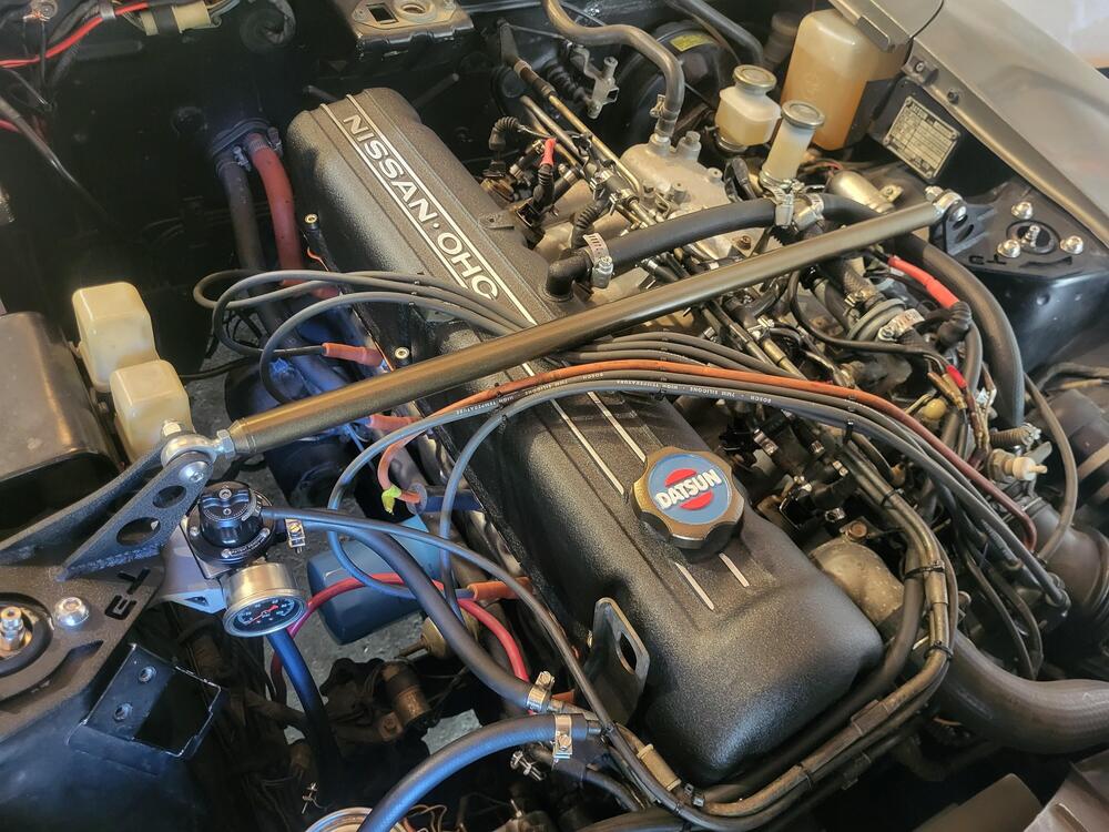
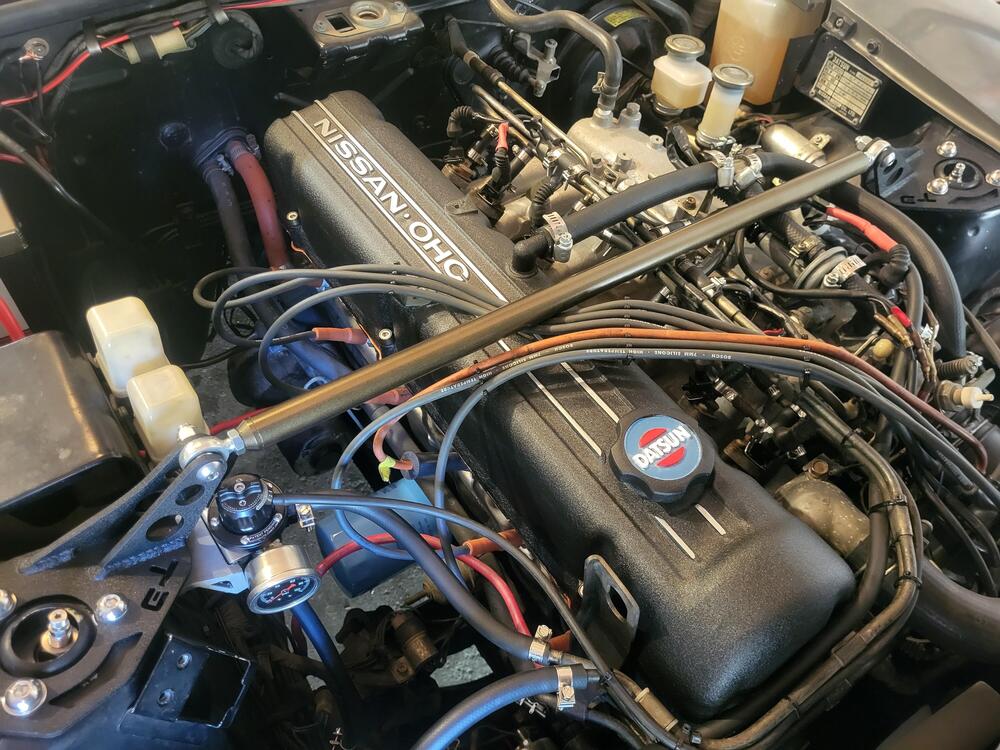
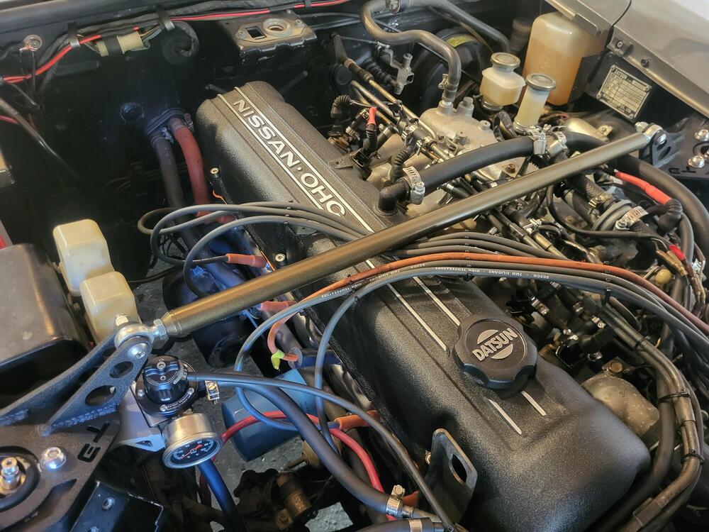
There were no oil caps that spoke to me for the 280z (or they were $100+ billet caps). I have also been interested in the process of ordering 3D printed metal parts from China so decided to kill 2 birds with 1 stone and design my own oil cap and then send it off the China to be printed out of Aluminum. I opened up SolidWorks and got to work designing an oil cap vaguely based off the NISMO oil caps. I ended up with 4 different designs. After printing them all out of PLA to test the threads (I had to manually CAD the threads as the size and pitch were not an option in the thread tool), verify the o-ring groove had enough stretch, how they feel, and how they look on the valve cover, I decided to go with the bottom right design. With the design chosen and geometry verified, I went to a website called CraftCloud and uploaded my model. CraftCloud is a website that aggregates companies that offer 3D printing services (both plastic and metal, CNC, Sheet metal fab, and casting services. You upload a model, chose the process you want, chose the material, and then you get a list of companies and their quotes for the model you uploaded. After a month of waiting, I had 4 oil caps (one cap ended up being below the minimum charge so I decided to order multiple) show up at my door. Final price (shipping + tariffs) was $237.87 for four caps (about $60 a cap). The initial quote was lower but the threads ended up needing to be post processed on a CNC grinder to remove support material from the thread teeth, this added an extra $90 to the price. With the oil caps in hand, I decided to powder coat each one in a different color. Two of the caps I was a little overambitious and tried to do a 4 color powder coat but that ended up failing and I used enamel paint for the DATSUN logo and the sun. The multi-colored ones turned out a little sloppy but I'm happy with them since I've only ever done single color powder coat before. I'm leaning towards using the multi-color bronze cap but haven't ruled out the bronze with polished logo.


-
I already have them in hand and powdercoated. Nylon or ABS should be able to hold up to the temp on the valve cover so I could've printed them at home but I used this as a test run of the 3D printing services. Also could've been CNC but for the specific geo of the cap, it wouldve been more expensive! I do plan on using the CNC options for something I'm designing for my subaru though.
-
I'll go over the process in the new thread but I made my own model using CAD, 3D printed it out of PLA myself to test the shape and make sure I modeled the threads correctly, uploaded a file to craftcloud (i find they have better options than xometry), chose a material, chose a company, and then wait. Its metal additive manufacturing though they did need to post process the threads with a cnc. Craft cloud/xometry can also get you quotes for CNC and plastic 3D printing using filament that are pretty much unobtainable for hobbiests (PEEK, etc). For metal 3D printing, Al is by far the cheapest but they also have multiple grades of stainless steel, iron, titanium, and even super alloys like inconel.
-
-
Ended up taking a break from this issue due to a leaking brake MC and some other issues but finally got back to it. I tried everything on the list above and still wasnt able to narrow it down. I ended up running a gound directly to the battery for the turn signal circuit on my halo headlights and that helped but the right and left turn signals are still not synced while the engine is running. They are a lot closer in cycle speed now and I'm going to call it good for now since I am planning on making a new body harness eventually and that should (hopefully) fix the issue for once and all. Thanks for the help everyone. I'll make a new thread for it but I also ended up designing and having some oil fill caps printed out of Al since non of the options on the market spoke to me or where more expensive than having some custom ones 3D printed!
-
List of things I will be testing soon, I will reply to this messages with results as I do them. Run a direct ground to the battery and the turn signal wiring Disconnect headlights Swap LED headlight units and see if rear turn signal issue follows Run the fuel pump with the engine off to see if it is inducing electrical noise Direct wire the pink +12v wire to the positive battery terminal or an external power source Swap the turn signal and the 4 way flasher relay double check the voltages on the boards themselves. Take a video of the condition that Captain Obvious requested earlier
-
I'll try disconnecting the headlights and see if that does anything. Since the headlights I bought were supposed to be direct drop ins and not generic 7" lights, I assumed the company I bought them from would have made sure the polarity of the connectors was correct (I'd also assume that if it wasnt, the headlights would not turn on at all due to them being LEDs).
-
-
-
-
-
Front are entirely new LED (with correct reflector so Im not blinding people) drop in units. I didn't have time to swap bulbs but I did unplug the running light/turn signal portion of the headlights and the cycle on the rear is a lot closer but left side is still slower (not erratic this time though). 20260122_112411~2.mp4
-
-
I was re-reading the emails I had with the LED manufacturer and I think I might have a new lead. "The rate at which the LED taillight panels flash a turn signal is determined by the flasher module and whether the LED taillights are in sequential mode or not. When the taillights have +12 volts power on the LED panel's Pink wire or the Running/Driving lights are On, then the taillights will flash half the frequency that is output by the Flasher Module. The front lights will flash at the same frequency as the Flasher Module. This is because the microprocessor must wait longer than one flasher module cycle to determine whether the +12 volt signal on the Brake/Turn Signal wire is a brake signal or a turn signal. After that determination, the microprocessor will start another illumination cycle. When the taillights do NOT have +12 volts power on the LED panel's Pink wire or the Running/Driving lights are Off, then the taillights will flash at the frequency that is output by the Flasher Module. If the two sides of the LED taillights are flashing differently, then they are likely being presented with different electrical signals. I hope this explains what you are observing. If you have any further questions or if there is anything else we can do to help, please let us know" In addition to the rear LEDs, I also have halo style headlights and the way I wired the running lights on them to an ignition source, not to the the side markers so my running lights are always on. I installed the headlights after I had done the taillights so that checks out why the initial test on the board was behaving as expected but now they no longer are. I'm still confused about why it is only the left side and not both sides since I wired the running lights up front in series from the from the same power source so I'd expect both rear turn signals to be affected.
-
Put the left side into mode 1 (normal blinking) and kept the right side on mode 3. Looks like a full cycle is supposed to be 1.25 sec long. When the engine was off, both side took 1.25sec to complete a cycle (40% duty cycle for left side and 80% for right side). Once the car was running, right side still had a cycle of 1.25 with an 80% duty cycle but the right side was erratic. I timed 3 cycles and got; 2.5 sec cycle (50% duty cycle), 2.9 sec cycle (40% duty cycle), and 2.5 sec (50% duty cycle). Looks like the overall cycle is half the frequency but with an erratic duty cycle. Still need to test with car off but fuel pump running.
-
-
Running the fuel pump is a good idea. I don't think its overly noisy but the fuel pump in my daily is much louder so I might have a bad baseline. Talking about out of left field ideas, I could insert a voltage follower into the turn signal wire on the left side, if there is really something weird happening with impedance, that could help (maybe).
-
I can check the 12v pink wire, maybe my crimp is failing after the right side, not sure how that would play into sequential mode working fine while running off the battery but not the alternator though. Seems like a power quality issue from the alternator but nothing else appears to be affected I haven't tried setting the board to standard flash with the +12v pink wire, I've only unplugged it. Thats a good idea. Its a 1976. Shouldn't matter but the power antenna and rear speakers have been disconnected from the harness
-
Not sure if its the standard ground but it looks like the ground for that section of harness is directly in the middle of the trunk, right behind the license plate. I'll try running a new ground directly from the battery to check. Both flasher relays were replaced with the units recommended for the boards.
-
-
It's definitely driver side body harness. I'm lost where to start looking at the harness though. I tried videoing the trigger signal on my multimeter to see if there are differences in peak voltage and frequency they switch at but it was hard to see anything concrete with just a multimeter and not a scope, passenger side might be around 1 sec slower for a cycle but its hard to tell.
-
-
-
I'm running into a weird issue that I've tried chasing down but am at my wits end. I retrofitted these sequential LED Brake/Turn signal boards (https://www.dapperlighting.com/products/1974-1978-datsun-260z-280z-advanced-sequential-led-tail-lights) a few months ago and everything worked as expected. At some point, when the driver's side turn signal was active, it would flash erratically (not at half frequency) but only while the engine was running, if the engine was off the turn signal behaved as normal. This is also only when in a sequential mode, if I disable sequential mode, the turn signals flash as expected. When I did the retrofit, I also installed new flasher relays that are supposed to be low voltage ones for use with LEDs. I have contacted the company that makes the boards and they havent been much help. Things I've done to troubleshoot: Move the sub harness between drivers and passenger side; issue is persistent on left side Plug in passenger side turn signal to driver side harness; issue is persistent on left side Check continuity on all grounds for the harness Check alternator for steady 14.4 V Check turn signal trigger signal between left and right Bench test the LED boards with a battery pack The problem is related to something on the left light body harness but I have no idea what it could be, especially since the sequential turn signal works fine when the car is off but not while its running. Any help would be appreciated. I'll upload some videos when I get home later today