RJK
Free Member
-
Joined
-
Last visited
Everything posted by RJK
-
SteveJ-AMAZING info here. very clear. thank you SO much. it's complicated stuff; I had to read your entire paragraph 2-3 times before I could visualize what you were describing, but now I think I can. In essence, it seems as though the white wire and white/red wire run thru a network, that includes the fuse box, ignition switch, and ammeter when they travel into the cabin. by disconnecting the molex connectors, and the connections in the engine bay, I am breaking apart that network. now, by testing at the connecting points, i can see where the network is grounding out(or close to it). very clearly put. I'll implement this procedure today, and report back.
-
More info: 1-disconnecting this single pin, white>white red connector at the PS footwell ALSO drops impedance to OL. 2-impedance from red/white alternator wire to ground is 2.6 ohms. 3-removing 4th fuse down on right side has no effect on the ~3ohm reading I get from fusible link wire to ground.
-
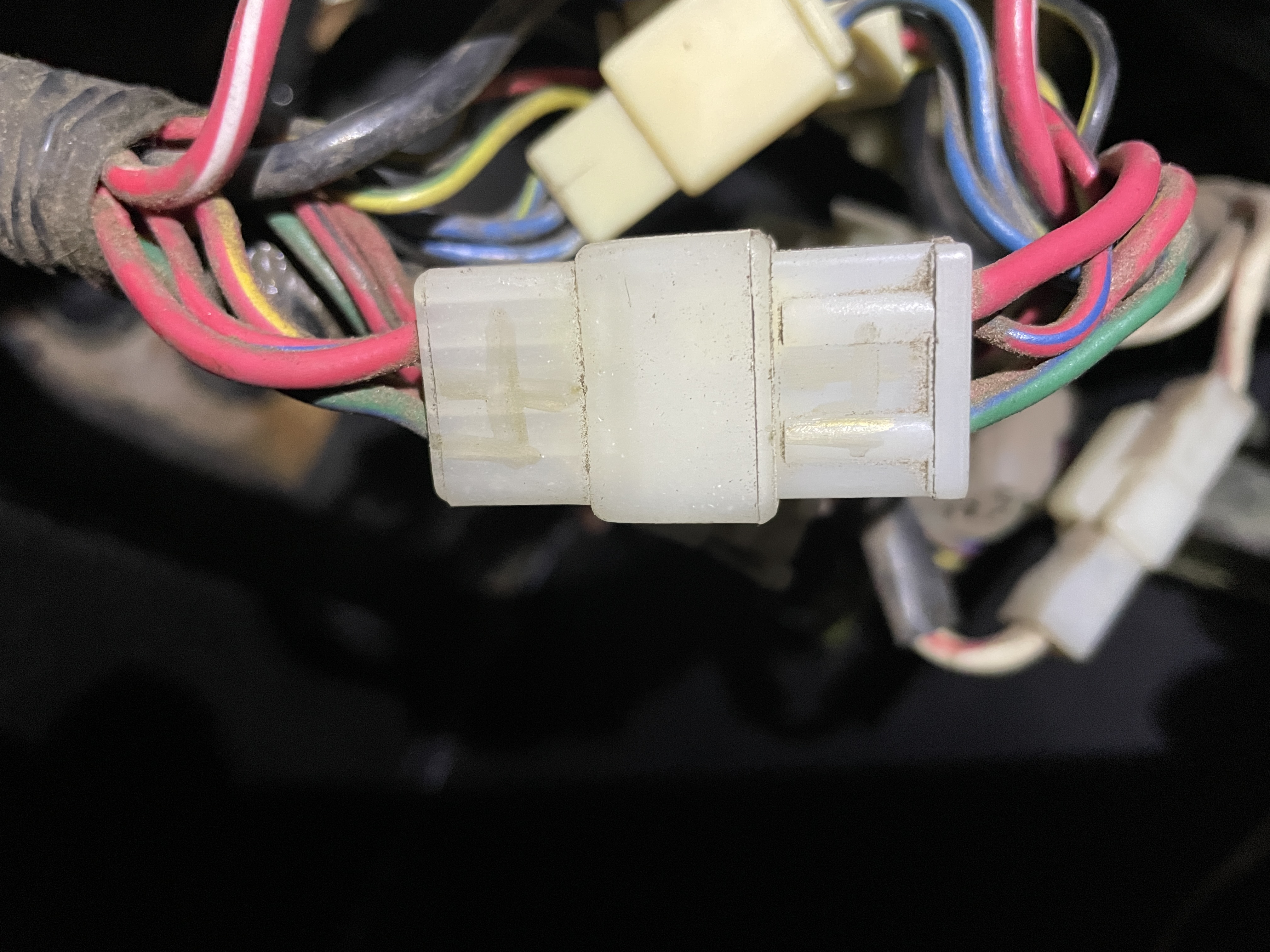
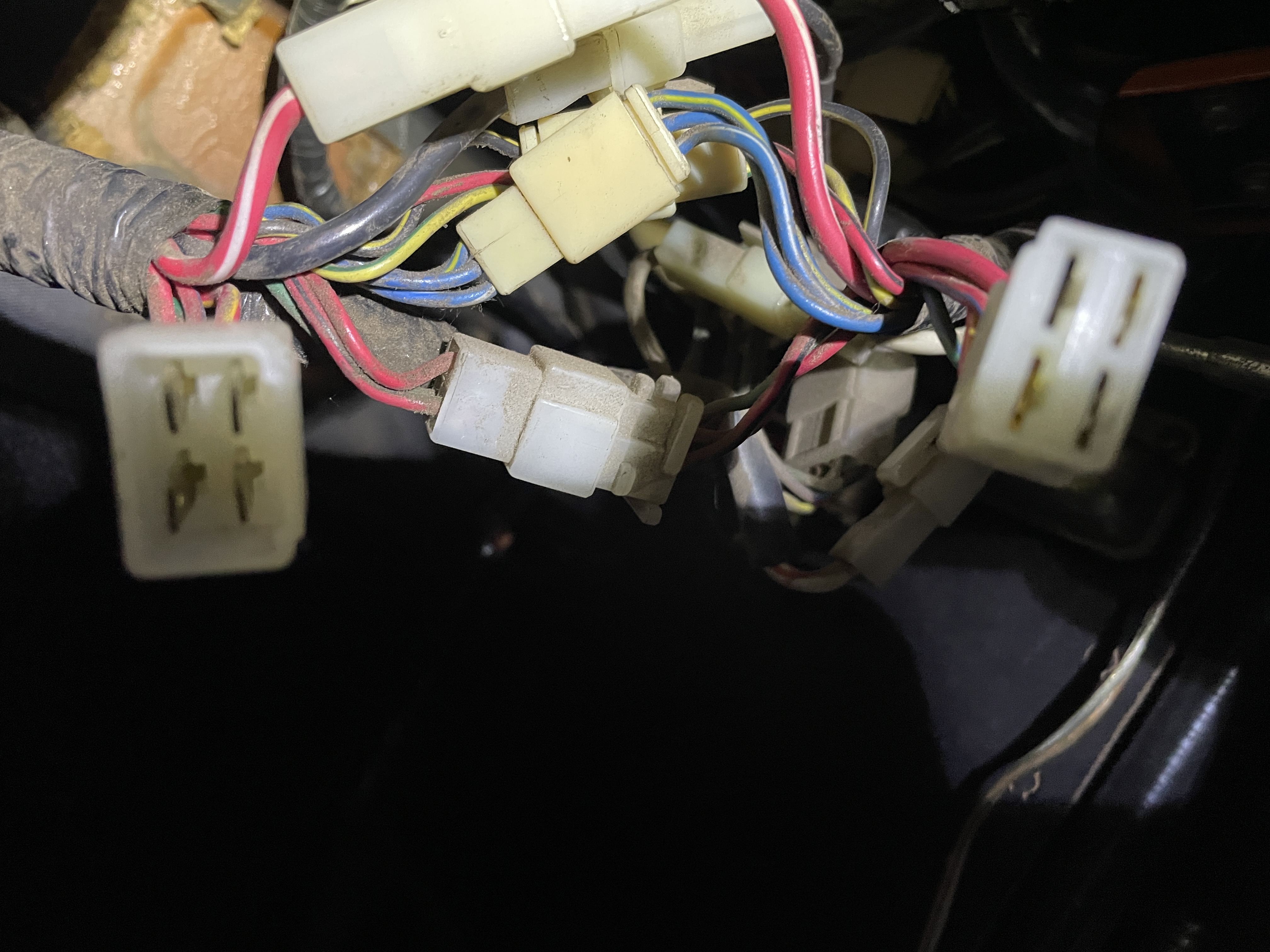
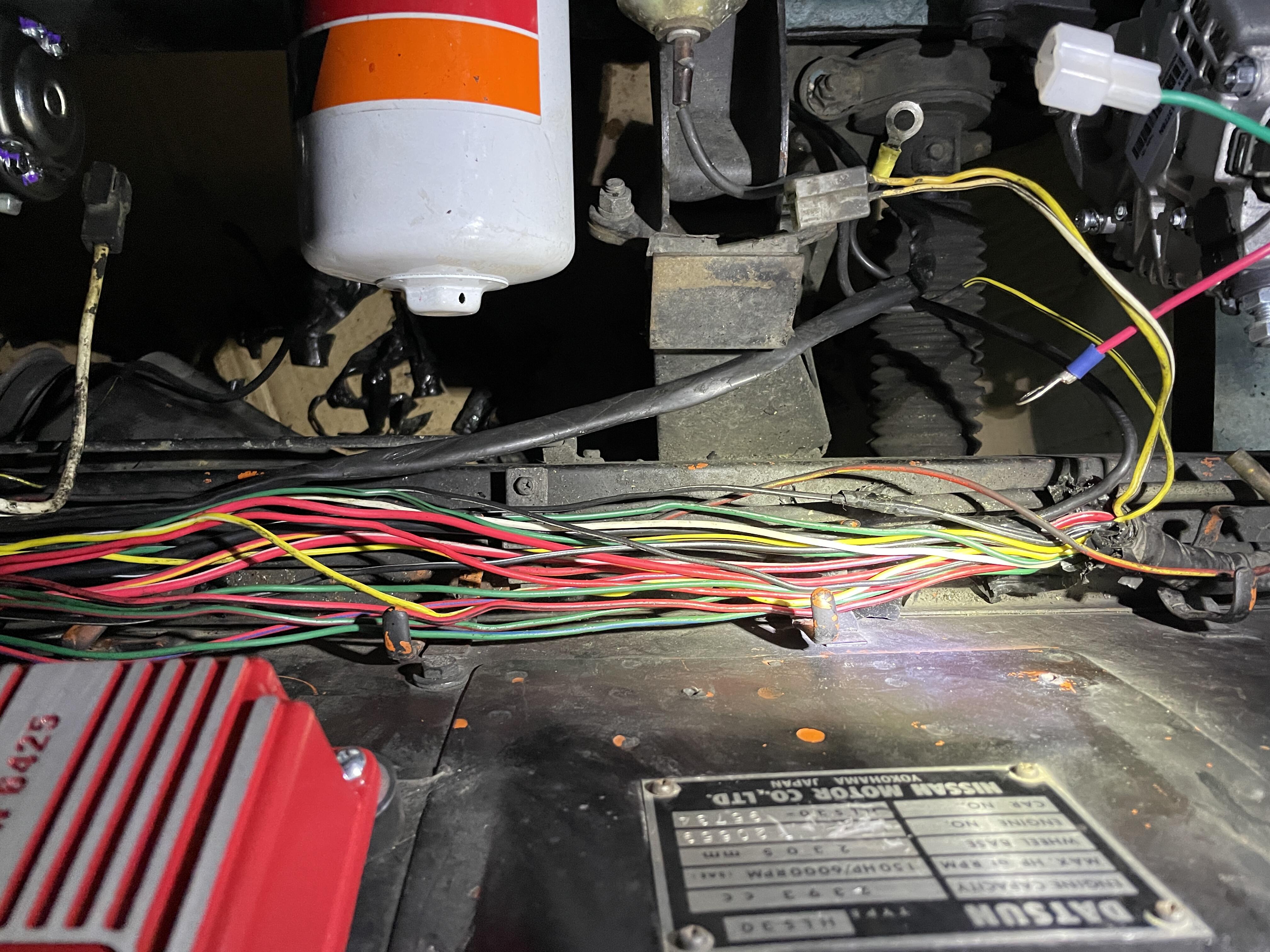
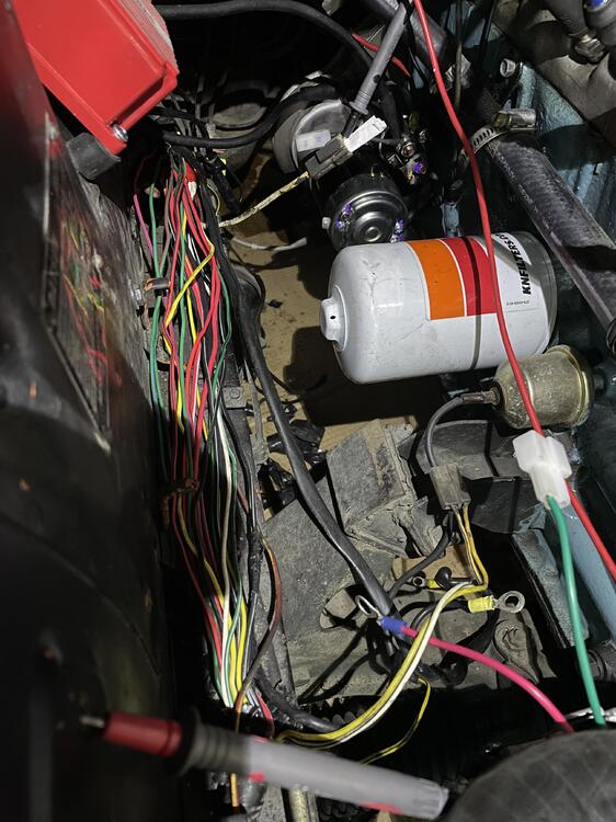
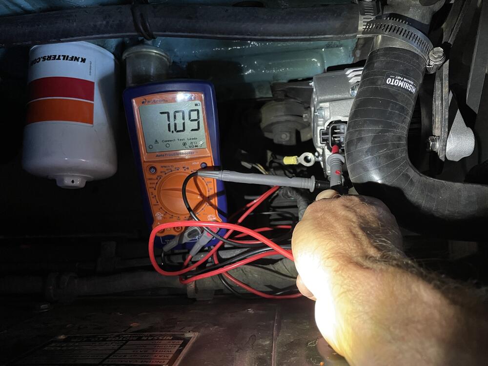
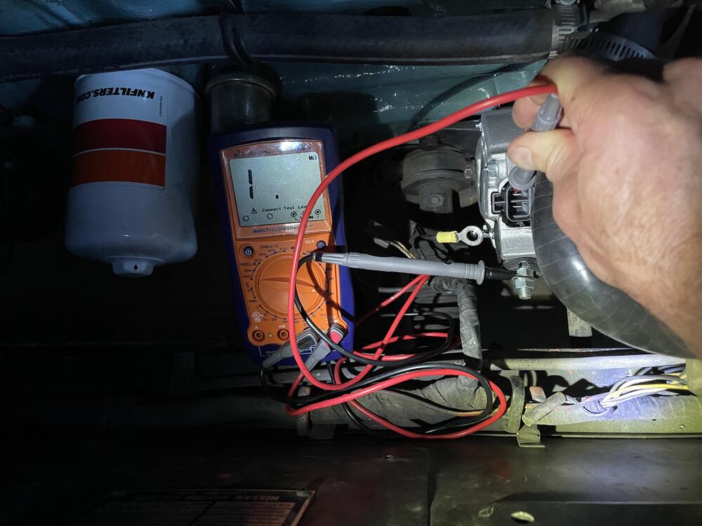
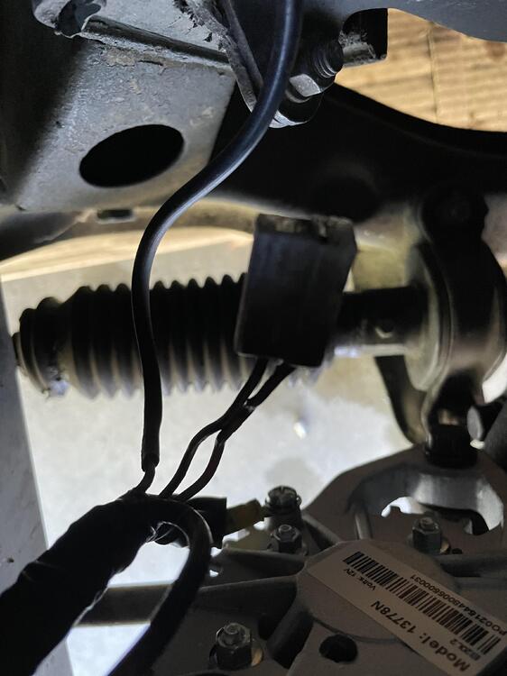
Ok, more diagnostics, and pics. I found the molex connector in the PS footwell that links to the fusible link wire. In the pics, see a 4 pin connector; when I pull it, my impedance goes OL. Obviously, I need to figure out where this traces to, but this is progress.


-
alternator is disconnected until i know i'm not sucking current or creating a fire somewhere. so not connected on reading. 1972 240z, only upgrade is MSD ignition, wiring appears to be stock.
-
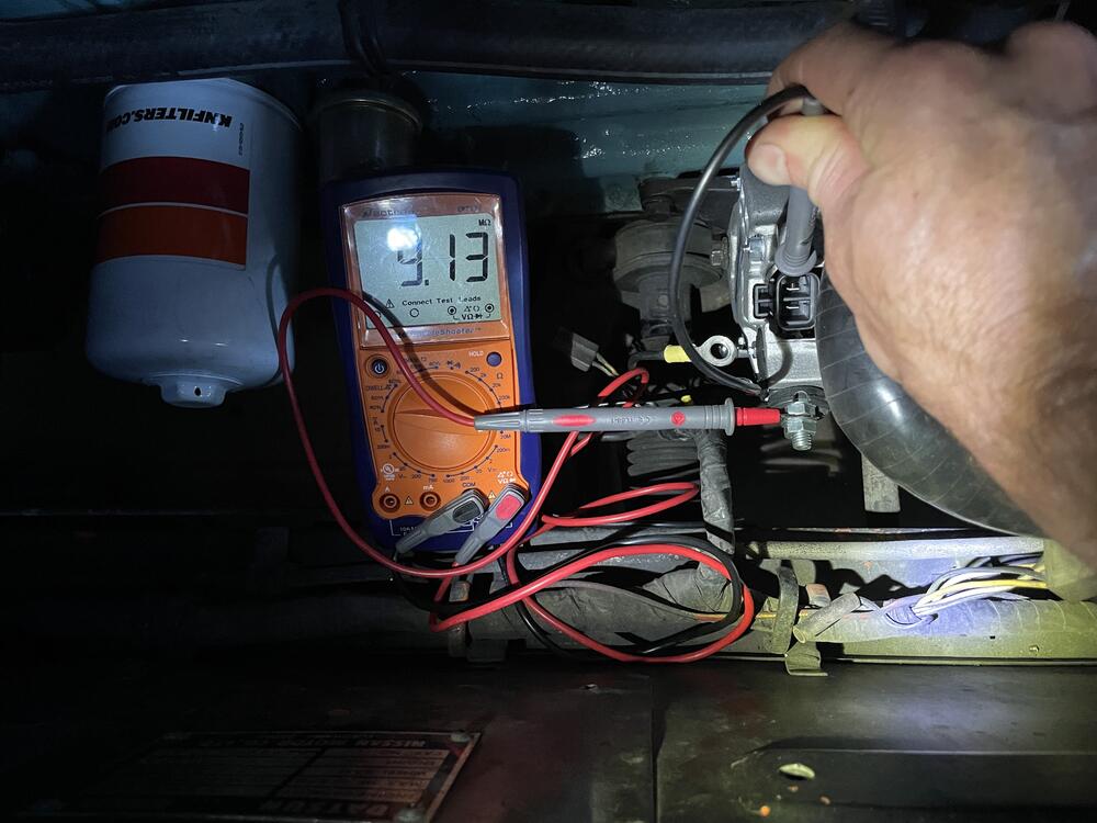
Thanks Steve-yes, I was measuring the same test points it looks as though you were measuring. To clarify, at the fusible link that connects the starter to the car wiring(single pin molex style connector), I disconnected the fusible link, and measured with positive probe at the CAR'S wiring harness side of that connection(in your image, it would be the old and faded side of the connection), and the ground probe at numerous chassis points. With the battery disconnected, I am averaging around 3 ohms.
-
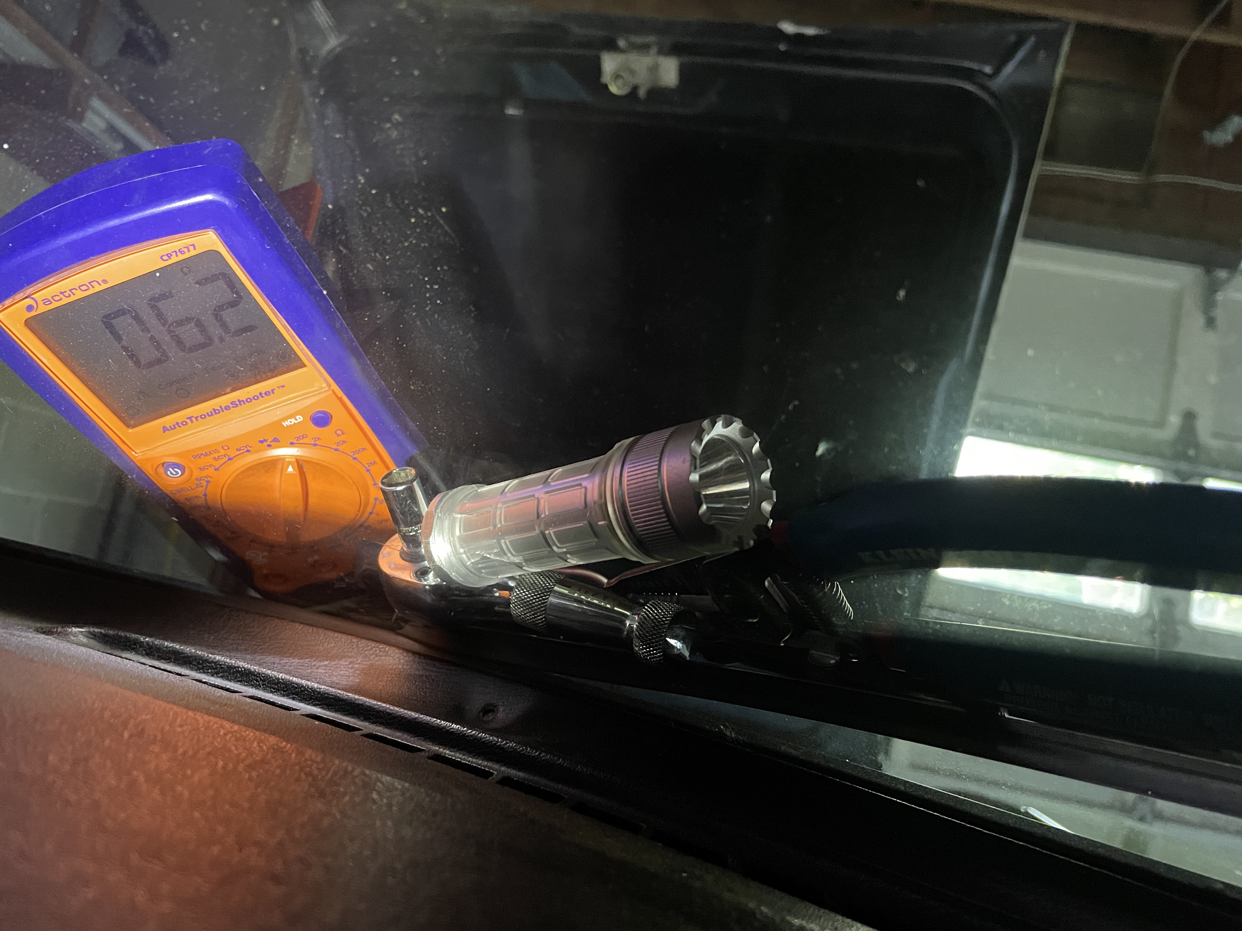
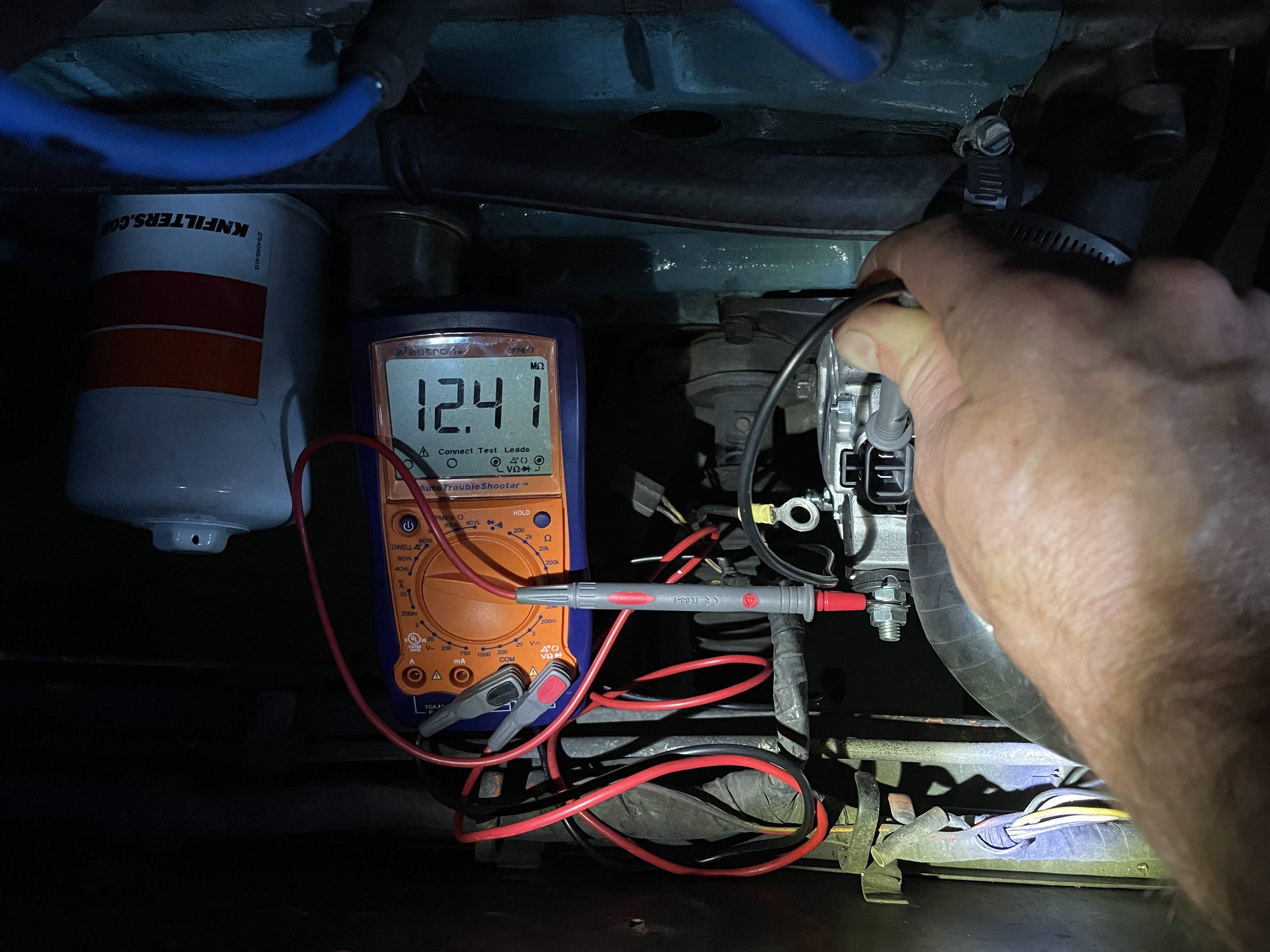
Ok, so I just tested: Remove the fusible link and use a voltmeter and measure from the wire coming off the solenoid (for the fusible link) to the positive battery cable. If there is not a short, that should read 0V--- I DO NOT HAVE THE BATTERY LIVE, SO I DIDNT READ THIS IN VOLTAGE. IN OHMS, IT'S OVER 1K. Measure resistance between the wire coming off the solenoid (for the fusible link) to ground. If it reads less than 10 ohms, you have a significant load or short. If you have less than 1000 ohms, you will have a pretty good battery drain. -THIS READS AT 2.6OHMS TO 3.1 OHMS, DEPENDING ON WHICH CHASSIS LOCATION I USE. BUT CONSISTENTLY IS AROUND 3 OHMS. Use a 12VDC test light between the wire coming off the solenoid (for the fusible link) to the positive battery cable. If it lights up, you have a short. (Be sure to test the test light across the battery terminals to make sure you have a good bulb.)--DONT HAVE ONE OF THESE YET. So I think it's safe to say I have a short somewhere, or a load? Should my next area of focus be at or near the ignition switch? (PS-forgot to mention that for now, as a baseline, I am working with battery disconnected, alternator disconnected, and fusible link also disconnected. 6 pin VR harness adapter is seated)
-
Thanks much, folks. I appreciate this! As soon as I get a chance, I'll pop a 5A fuse in line with the ground terminal, and assuming it doesnt blow, measure my current on a DVM. That's exactly the kind of "first step" I was looking for!
-
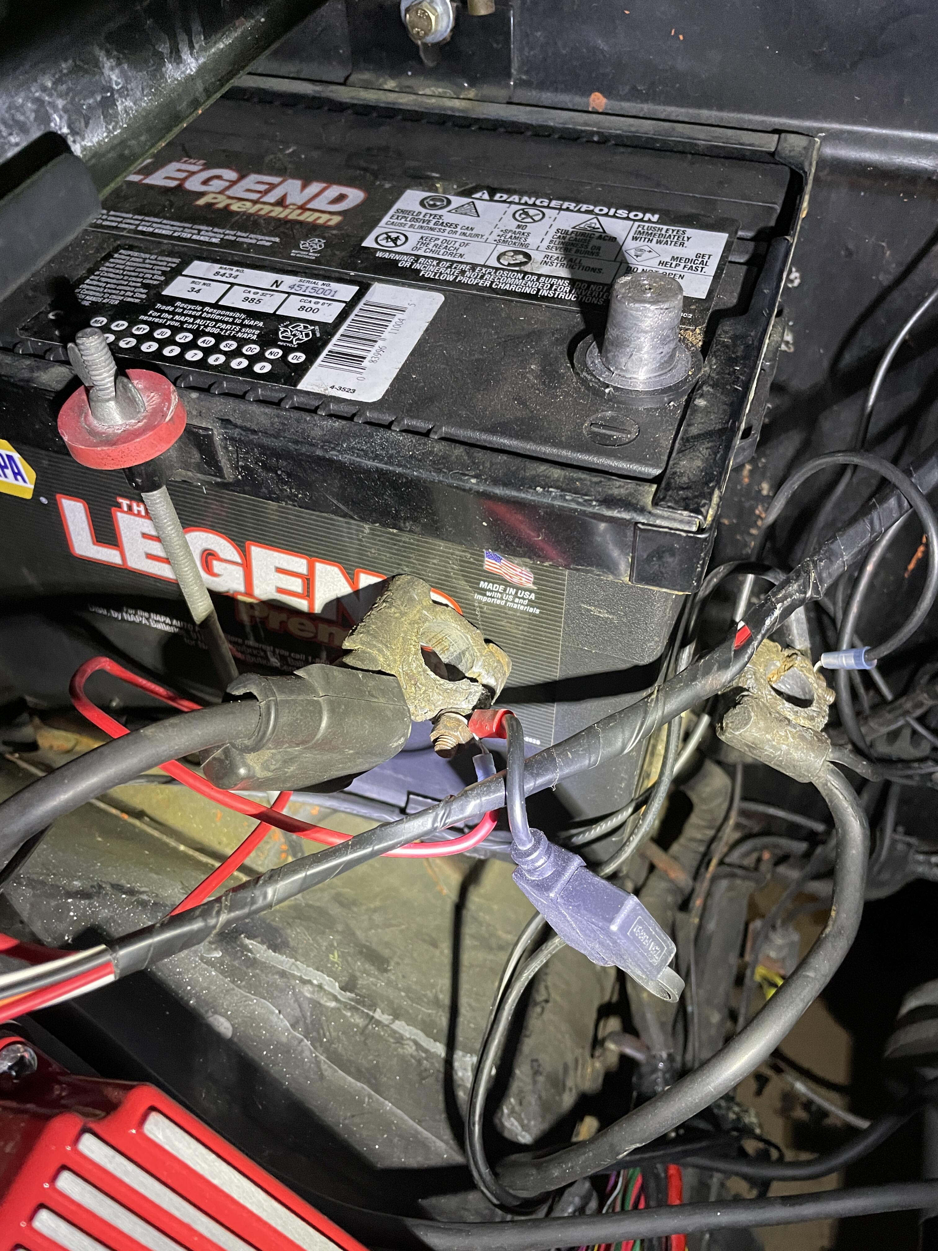
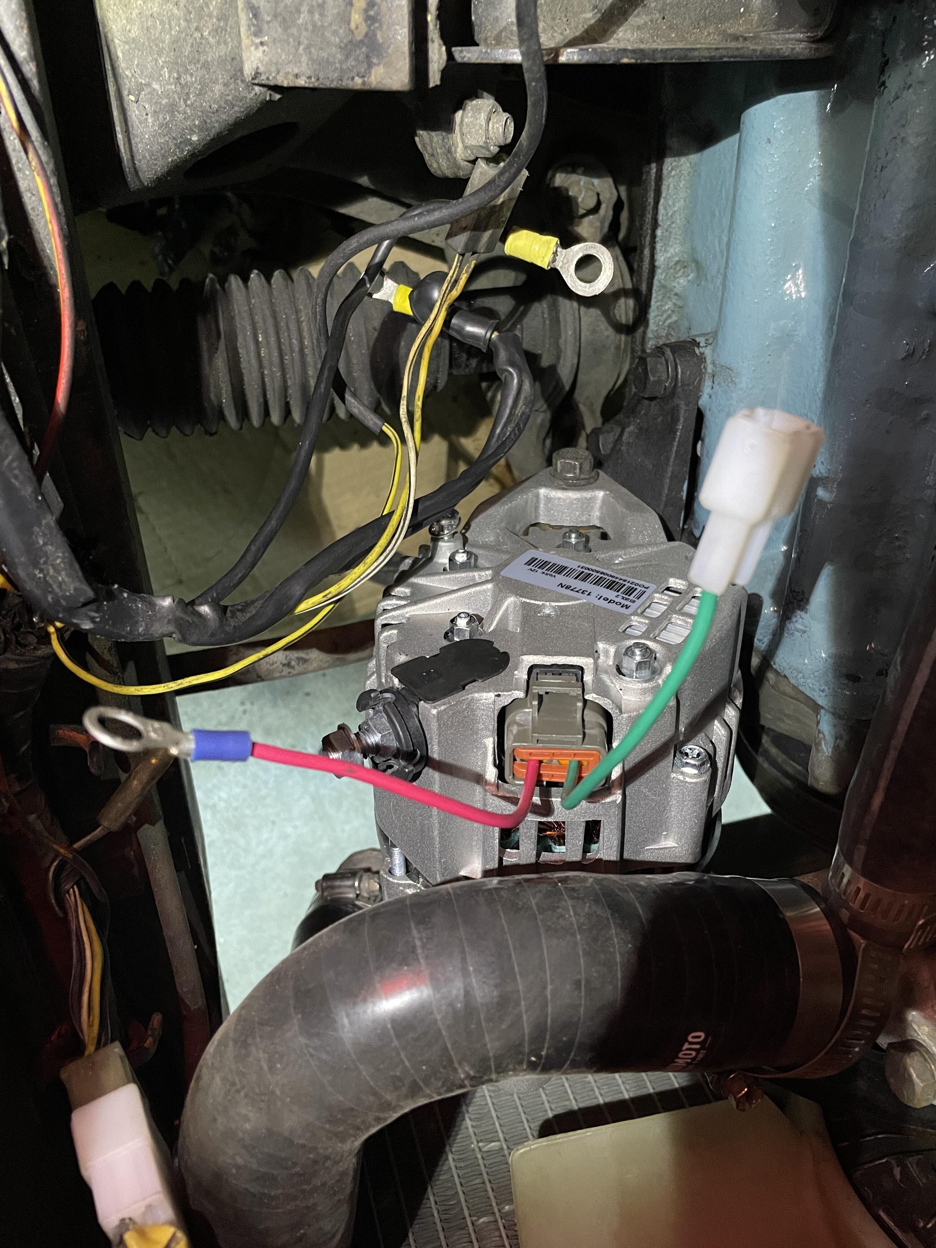
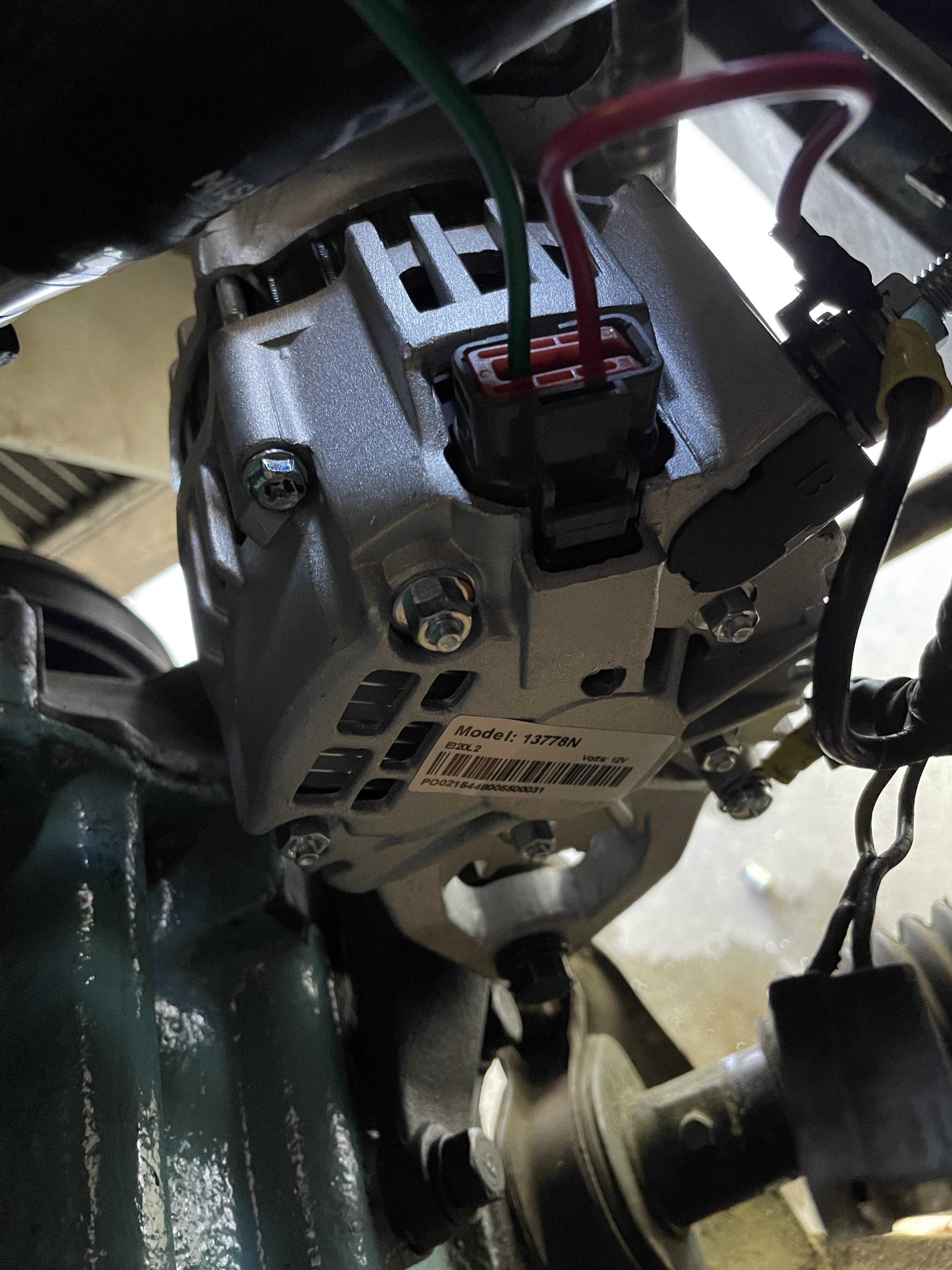
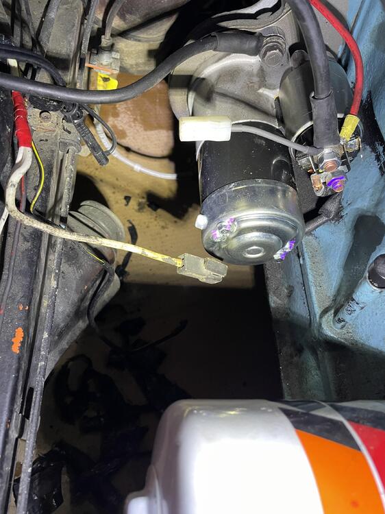
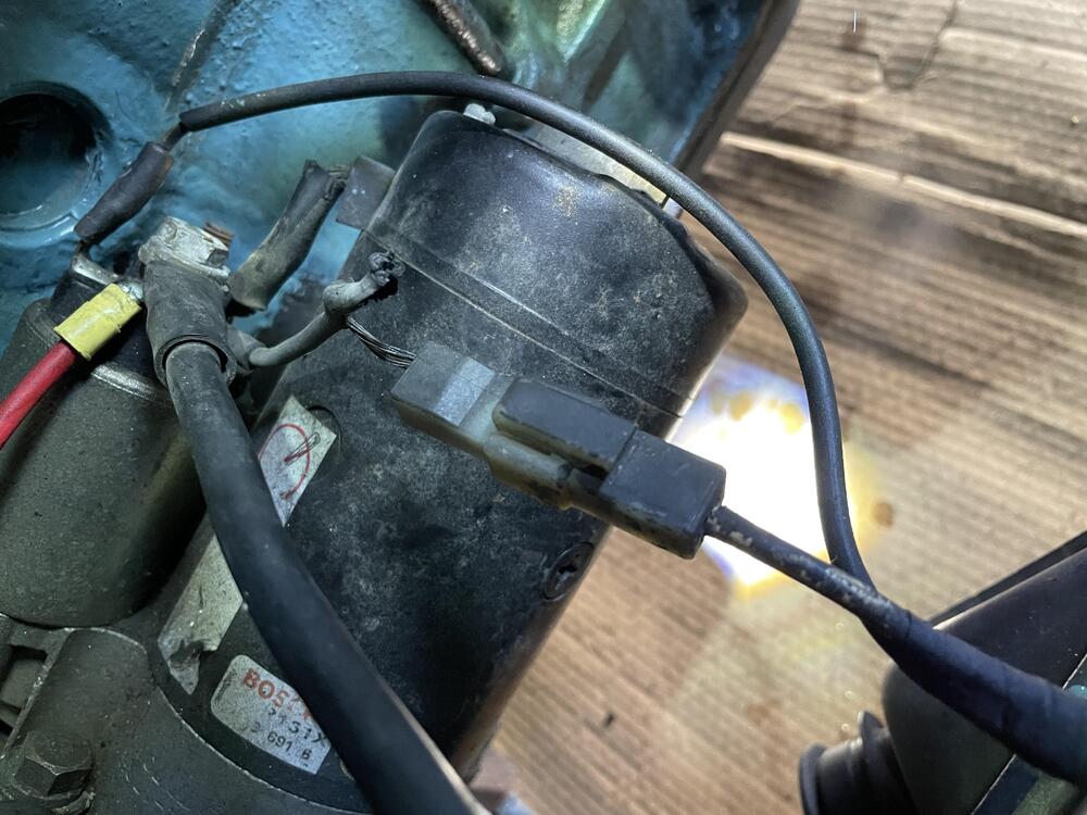
Thanks folks! Pics and specs here: -1972 240z, MSD ignition, otherwise stock. -I have replace the fusible link. I also bought one spare. I bought the nylon connectors, so I have a T connector for the new alternator. I still need to wire the "cross" pin of the alternators' T connector to the alternator harness. -when I was removing the wiring from the starter, the threads on the +12V post seized, so I replaced the starter with a new Delco unit. -I unbundled the wrap of the wiring from the starter to the alternator, so I could see any possible short there. All the wires look undisturbed. My next guess for a short location would be at the ignition switch, but that is just a guess, and why I'm here! See attached pics; thanks for the help!


-
Hi all, I suspect I have an electrical short somewhere, and could use some help going about how to find it. I recently was replacing my alternator, and initially inverted the + and ground wiring to the alternator(combination of not labeling the stock wires, swapped location of posts on new alternator, and my being a bonehead). Upon connecting the battery, the fusible link did not blow, but cooked the insulation off the wire. The wiring lived for maybe 6-10 seconds before I realized what was happening and disconnected the battery; I cannot be sure I didnt cook some insulation off a wire elsewhere in the car. I have replaced the fusible link, and pulled the wrapping off the section of wiring from the starter to the alternator-I saw no shorts or burned insulation. With the alternator wires completely disconnected, when I attempt to reconnect the battery terminals, I get sparking that definitely does not look normal. I need to go about testing the system in a manner that is A-safe, B-logical, and C-not so wasteful. In particular, I don't want to keep blowing fusible links, if possible. I have a DVM, sufficient spare wire, fittings, and tools to repair and rebuild wires. Thanks so much for any possible culprits, starting points, etc.
-
Wally-your new alternator looks to be the same design as the one I have, from ZCarDepot. I feel compelled to reiterate this: I also connected the + wire of the car to the ground of the alternator. Luckily, your fusible link worked; on mine, the wire maintained integrity, and burned off the insulation. The rub there: I think it's highly likely I have a short on the +wire to alternator that is hidden in the wire wrap. This seems to be a pretty serious safety hazard, especially if a fusible link doesn't blow. If I were you, knowing you definitely put those wires under a similar duress I put mine under, I'd check the sheathing on your alternator + and ground wires, at least with a DVM. (can anyone report back what an ideal impedance reading would be from battery harness + to alternator wire ground?)
-
Hey, I had this exact same instance last month on my '72. (Did you get your alternator from ZCarDepot by chance?) due to my car having the + wire on a small eyelet, and the ground wire on the large eyelet, I wired the alternator the opposite of what it should have been. I only had the battery connected for maybe 5-10 seconds, but it was enough to smoke the sheathing off the fusible link. I've replaced the fusible link, but I now read, from battery + harness to alternator + 0ohms, and from battery + harness to alternator ground, 3 ohms. I have a hunch that I also burned off some insulation in the wiring loom, and have a short. so be careful there.... I am planning on ripping open the wiring loom, and re-running ground and + wires to alternator, just to be safe.
-
ah, gotcha-thanks SteveJ! This is super clear. I've got all the parts on order already; as soon as they show up, I'll implement this. Thanks!
-
Ok, here are my readings: B+ post of alternator to DVM ground, alternator harness "12V" tab to DVM V+ =7M ohms B+ post of alternator to DVM ground, alternator harness "ignition key on" tab to DVM V+ =no reading B+ post of alternator to DVM V+, alternator harness "12V" tab to DVM ground =12M ohms B+ post of alternator to DVM V+, alternator harness "ignition key on" tab to DVM ground =9M ohms Also, this is going to sound daft, but I really like to eliminate ALL assumptions, in general. My car has two eyelet tabbed wires for the V+ post and ground post of the alternator; the large eyelet reads 0 ohms to chassis, the small eyelet reads about 160 ohms to chassis. This means that the large eyelet wire ties to alternator chassis, and the small eyelet to B+ post of alternator, correct? If so, I had this backwards initially. The small eyelet tab doesnt fit the post on the new alternator, and the positioning of the posts is actually inverted on the new alternator, so I didn't even stop to think to throw a DVM on the wires....

-
Zed Head-yes, that diagram does show the wiring. I currently have the "12V post" wire tied off to the B terminal of the alternator. the wiring diagram from ZCD on the harness itself is already kinda iffy, so in the interest of being thorough, i was trying to verify 100% this wiring. Thanks for that!
-
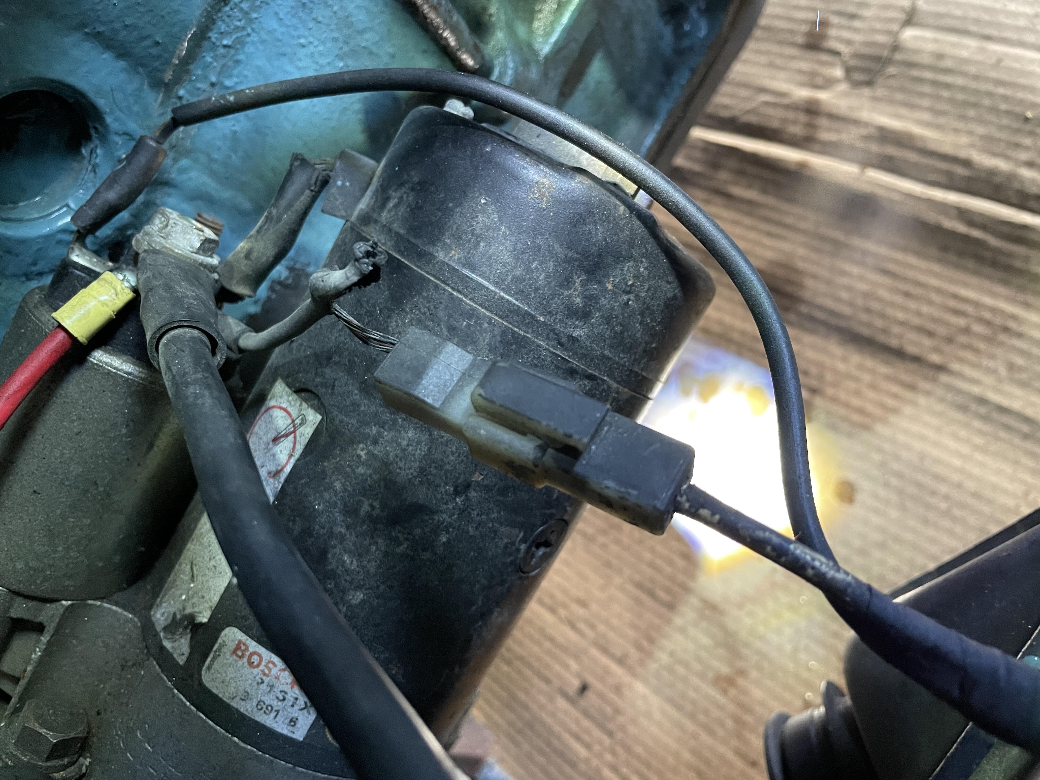
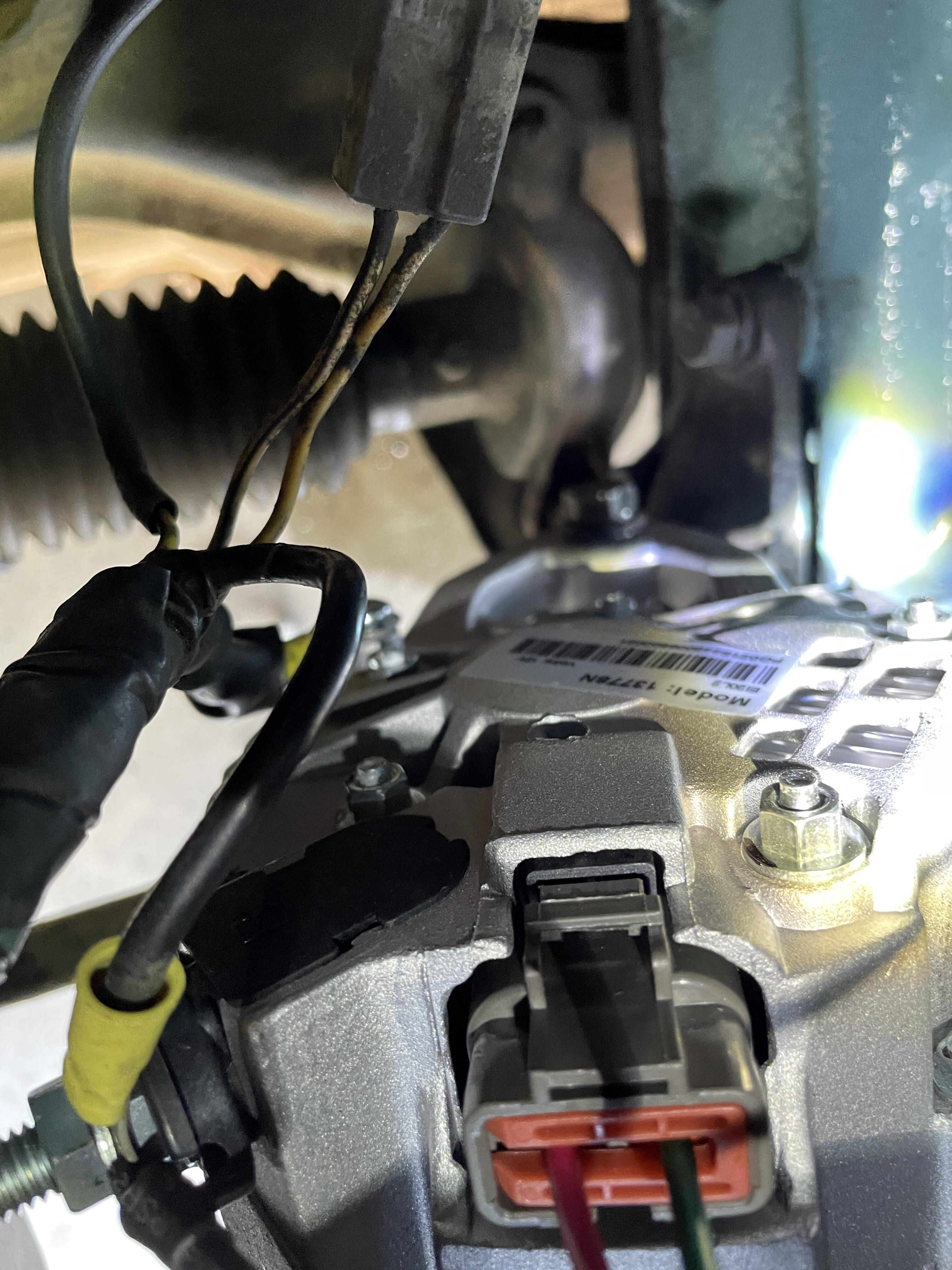
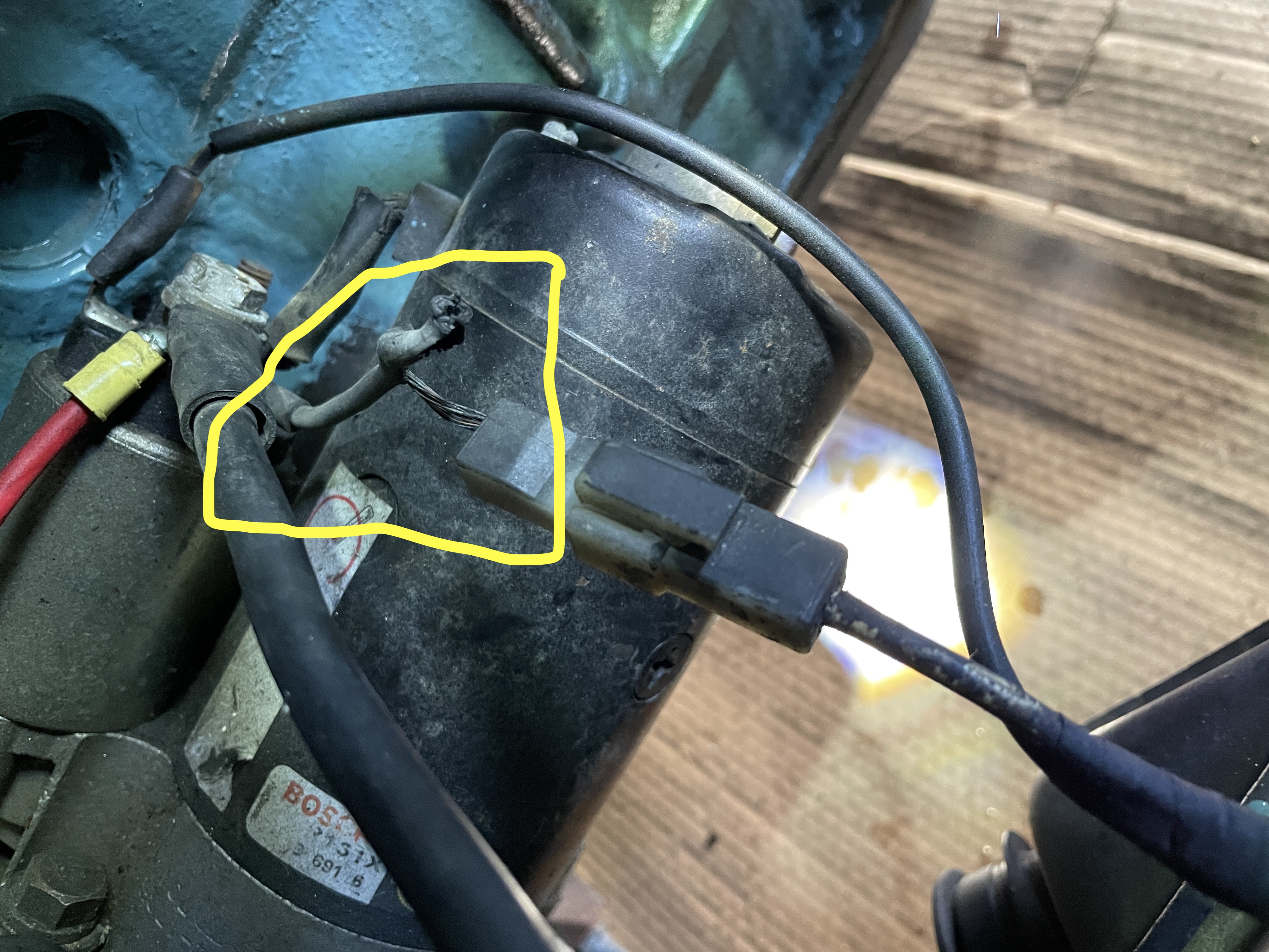
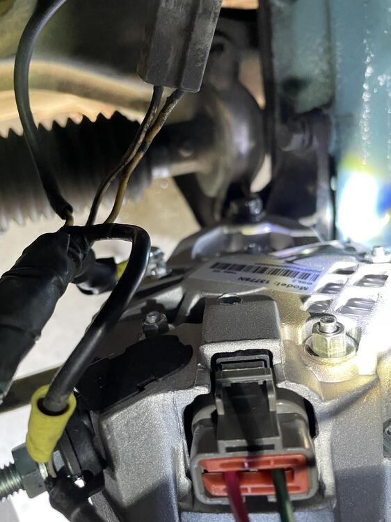
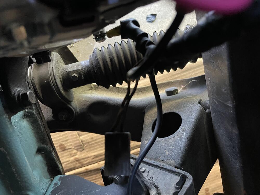
Thanks again for all the help, guys-really appreciate it. Attached are pictures of the alternator, as well as my fried starter wire. It appears as though I could just use heatshrink, and re-insulate the wire, but I'm also happy to roll my own from scratch(I have a lot of experience soldering via building synthesizers). The portion of wire to the right of the harness appears ok, visually. It travels through wrapping along the frame rail. I can test it on a DVM and see what it connects to; if there is unseen burned insulation that could be dangerous, I could always re-run that wire section in the interest of safety. On the alternator, I don't see any designations of the output tabs themselves. The +V is notated "B", ground tab is not, but it's obviously contiguous metal with chassis, so I think it's a safe assumption. Does anyone know the value of the diode in question for the 6 pin harness? I've got a ton of diodes here, and could easily roll my own with female crimp connectors, but wanna go in with the right value. Thanks!!


-
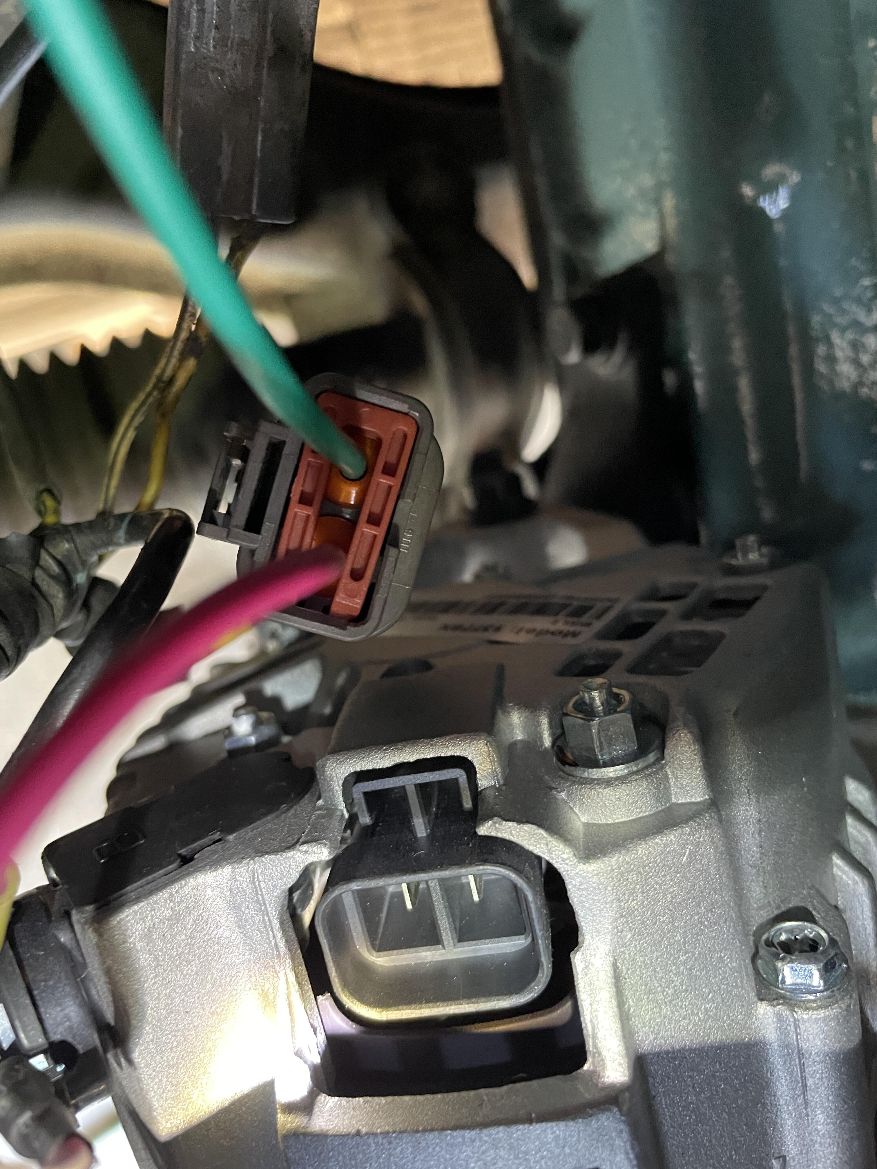
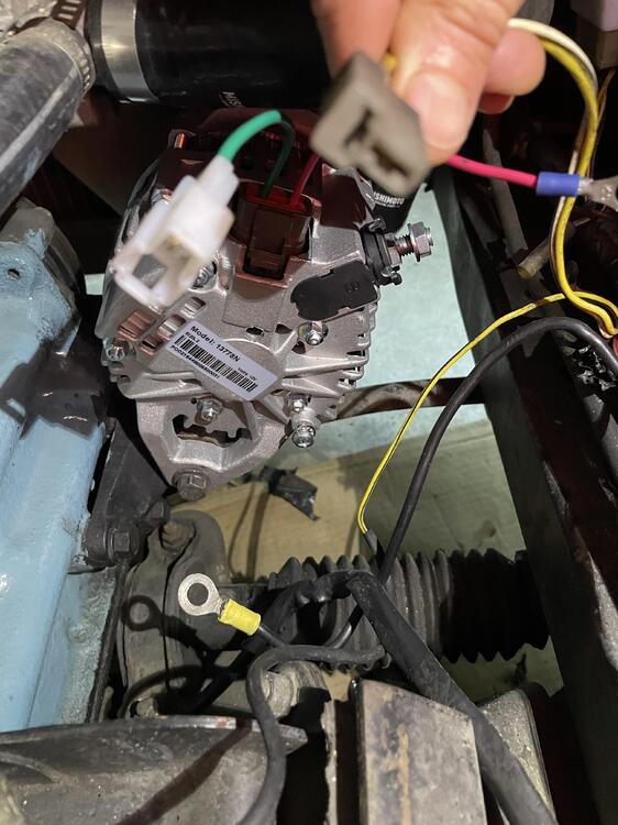
Thanks SteveJ! really appreciate your help. 1-so, to clarify, on the 6 pin harness, if I integrate the diode into that connector(either via the adapter thezstore sells, or roll my own), then I would connect the tab of the alternator labeled "ignition key on" to what you referred to as the "switched wire" in the T connector with no diode in line there, correct? 2-the image you sent matches the image of the harness that was on the ZCarDepot site, but not the actual harness. the actual harness they sent has a green and red wire-the red wire is where the diagram shows a green wire, and the green wire is where the diagram shows a yellow wire. this would actually make more sense, as the red wire would be 12V post. 3-that is where I have the earth eyelet wiring from the car I'll post images of the wire i burned some insulation off when I get some better light in there. thanks!
-
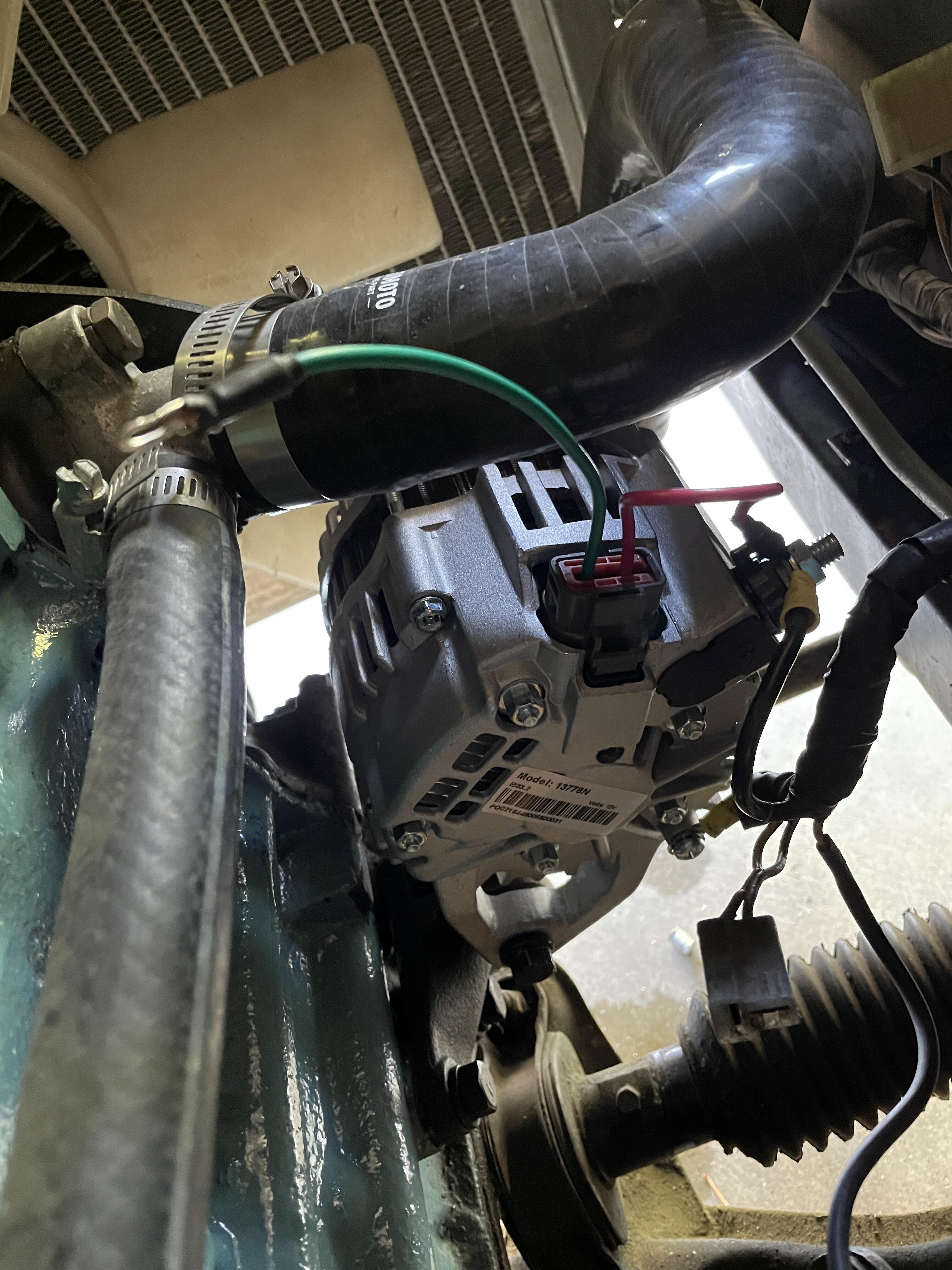
This is fabulous! thanks much folks. This makes the 6 pin harness wiring very straight forward. I'd still like to confirm a few things, just so I'm going back in as close to 100% sure as I can: 1- the 2 pin T connector that is at the alternator; how is that wired to the alternator itself? It looks like the only wire one of those tabs could connect to is the "ignition key on" tab of the alternator? 2-The language on the ZCarDepot site for the connector instructions is not clear at all. It refers to a yellow wire and a green wire. The actual connector they sent has a green wire and a red wire(green is the "ignition key on" tab, red is "12V post" tab, which is opposite of what they designate on the site). I currently have the red wire of the adapter, which connects to the pin labeled "12V post", tied off to the 12V post, as seen in the pictures. 3-this feels obvious, but I want a 2nd set of eyes on my work. The new alternator did NOT come with a bolt to tie off what I have to assume is the ground tab of the car's wiring. There is a threaded female hole in the location I'd expect it to be. The car's wiring has 2 eyelet tabs, one big and one small. I have the big eyelet tab tied to the 12V post of the alternator, and the small tab tied to this hole, with the proper metric screw seated in it. Again, seems obvious, but no stupid questions, right? My only other X factor is whether I cooked off any insulation on any other wires when I briefly connected the battery to test the wiring. I know I cooked off about an inch of one of the starter wires; I may just trace it, terminate it, and solder up a new wire for it. I know it travels thru the bundle that lives along the frame rail. Thanks again for the help, folks!
-
I have not jumpered out the VR. I will grab that 2 pin connector What spec diode do I need? As much as I'd like to think I'm a competent guy, I'd love to have a comprehensive list of everything I need to do to wire the new alternator correctly. As I was under the impression that the alternator was a drop-in replacement, and was internally regulated, the ZCarDepot site let me to believe I could drop this in. I briefly tested the battery connections after wiring up the alternator, and smoked a bit of insulation off of a starter wire(looks like I did indeed briefly backfeed the ignition circuit). I really wanna do this safely and correct. There is a good amount of data of alternator swapping across years/models for Z cars out there, and a lot of it varies. I really appreciate you guys stepping in and helping me out, especially since the data on the ZCarDepot site seems to be not only lacking, but potentially dangerous. Thanks.
-
Ok, so this is the alternator I'm going in with: https://zcardepot.com/collections/charging-starting/products/alternator-high-amp-80-240z-260z-280z?variant=19280584015985 harness is kinda hard to see, but one wire is yellow, one is white/black.


-
Hi all, I installed an MSD ignition in my '72 Z, and now the alternator is way under-spec-ed. Battery dead after 10 minutes of driving. I installed a new 70amp alternator from z car depot, and have one question about the factory harness. there's a 2 pin harness that runs to the old alternator location. the new has a tab labeled "ignition key on". I believe I'll need to manually wire this lead to one of the two pins of the car's harness. i can't tell if its the yellow wire, or the white/black wire. Any help would be appreciated. I found this data point on the 280z: F&N (T connector) N (Yellow) (on the early alt becomes the Sense signal on the newer alternator (the alternator "senses" the voltage on this wire and attempts to maintain it at 14.45V. F (white with black stripe) is the Field signal on the early alt that becomes the L lamp signal on the newer alternator."
-
-
Hey folks, I don't know if this is normal behavior, but I recently noticed that my 1972 240Z will show an oil pressure at idle of basically zero. In any gear, as soon as I give it some throttle, the oil pressure rises predictably to a "normal" range. Hold it at 3500-4000RPM for 5-10 seconds, and the oil pressure will rise to 50-70PSI. I did some recent wiring/ignition work, so I'm not sure if this recently manifested itself, or if I somehow didn't notice it for all these years. Is this normal, or concerning in any way? I would expect the oil pressure to drop at idle, but this is literally to zero. Seems strange. (side note: since installing an MSD 6A ignition box, I am having some strange gauge behaviors, at least at the tach.....what reads as 2k is absolutely not 2k-there's maybe a 500-700RPM "offset".)
-
Hi all-so I am the owner of a '72 240z, which is a blast to drive, but ever since purchasing the car, it has been plagued by a particular issue that makes it supremely unpleasant: the smell of either unburned fuel, or exhaust, in the cabin. I am not at all new to old cars and their smell, and I can assure you this is not the typical "old car stink" from a non-cat exhaust system. this is BAD. if the windows are rolled up, i can only drive maybe 3-5 minutes before it's basically unbearable(headache levels of discomfort). I've had two exhaust shops check everything downstream of the exhaust header-it's completely tight. the car will stall out if you block off the exhaust at the tailpipe. I have sealed off every interior vent with painters tape, and tested-no change. i have gone thru the firewall with a flashlight in the dark, and cannot find any noticeable gaps. I'm basically stumped. I don't want to get rid of the car, but in it's current state, it can only be driven with both windows down, and even then, i have to start sticking my head out the window after 10 minutes for air. this particular car has a fuel pump toggle switch at the center console FYI. my only thought at this point is that there's either A) a firewall leak i can't find, or b) something related to the fuel pump. has anyone experienced anything similar, or have any ideas? thanks, RJ
-
thanks! the gaps are narrower at the front of the door, between the door and fender, than the gap at the latch. pass door "half latches", if i grab it and shimmy up and down while pushing inward. driver door latches-also only halfway-on a gentle close, but i cannot for the life of me get it to "full latch". we did not pull the doors in paint, and the driver door latched perfectly with the old rubber. with the rubber out, it latches great, but i put a tiny chip in the paint closing the door with the rubber out, so i'm freaked out now about doing that!
-
Hi all-thanks for the helpful and informative forum here! I got my windshield in properly, thanks to you guys. Much obliged! So I recently blew my car apart for paint, and now have it back together. One of the last pieces of the puzzle now is getting the gapping right on the doors. I took the opportunity to put new rubber on the car, and now both doors don't fully close. The passenger door was always finicky, but the driver door closed great on the old rubber. I'm a little scared to adjust the door at the hinge, as I don't want to chip the paint. Any tips to adjusting the latching mechanism, or door hinge, safely? Thanks much for the help! -RJ