


Dave WM
Free Member
-
Joined
-
Last visited
Everything posted by Dave WM
-
 The test stand uses a turbo wire harness, it does not have a provision for the resistor pack like those on the early 280z fuel injectors. I dont know enough about the ecu used on the L20et (which seems to be this one) to know for sure what it was using in the way of injectors/resistors/impedance. Been hard to find data on it. IF i had a L20et setup car then I could tell for sure by just looking at the wire harness for a plug to use a resistor pack. The 280zx turbo ECCS wire diagram does not show resistors. From what I can tell the injectors specified are low impedance so it would follow that the ECU deals with the issue with out the need for outside current limiting. When I do testing on injectors I generally use a variable voltage source. I often will use a transformer coupled to variac and a single diode for a 1/2 wave 30 hz pulse This isolates line current and lets me adjust the current with the variac to just enough to trigger the injectors. I have found they need around 200ma IIRC to operate. Granted the pulse is sine not square, but I assume for testing that is ok. I just want them to open and close while I pump cleaning solution thru them.
 -
It all seems to work at least on the stand, it just I am concerned about the need for resistors in the injector + lead. A part diagram showed them. I contacted the seller, he is sending me a different part that should be an exact ecu for a turbo L28et, will give that a try when it gets here and do an update. No issue with RPM's etc that is fin on the test stand.
-
I think this maybe a L20et ecu, and that it may require dropping resistors to work properly. I have contacted the seller to clarify why it was listed as a L28et ECU 1982/83 unit.
-
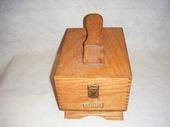
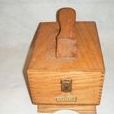
inside the ecu
-
PN A18-000 203 23710 F5910 works fine on my test stand, but has a hole next to the side mounted LED opening with what looks like a slotted round shaft. Its a pot, have not messed with it. I tried searching on the PN the 203 does not match with any thing. Talked to Jim Wolf tech support, they thought it could be a JDM thing, had not seen this either. since its a pot I don't think its for reading out data anymore. Its actually hooked up like a variable resistor (only two wires to the pot). The engine starts and runs fine, goes into closed loop (blinking of led after warm up an over 2k rpm). Below I started the video where I noticed the extra hole with the slotted shaft inside. I will be adding a video later with the ecu opened up to show the PCB's
-
no double stack they are pretty thick, if it takes more then there is something wrong. I dont know if there is any real preference, the one I used was a felpro, seemed kind of wimpy to me, more like thick cardboard, so you may want to try a different brand than that. IF nissan has them I would go OE.
-
check for vacuum leak by blowing smoke in thru a tube attached to the brake booster port on the intake manifold. use a stryofoam cup to block off the front of the AFM. you can have leaks around the intake/exhaust manifold gasket as well. Just look for smoke.
-
indeed, more details!! that is a very neat looking under hood routing going on.
-
%Oh yes, nichicon are the best, and get the 105c. I suppose modern caps are tighter tolerances as well so 20% was probably bad too. I was thinking of the old caps I used to run into on vintage electronics, they would often be like 100%+ 50%- rated, really wide ranges. This is stuff from the 1950's and 1960's. Tech has come a long way since then so I was off base on that 20%+-
-
hmm 20% off is not too bad with electro caps. Generally they have a pretty wide tolorance +/-. Seems like it should have been ok but maybe its a case of stacking with a non OE transistor. Anyway glad you got it going, but ditto the stop and restart check to make sure.
-
well decided to try my JY find, a literal pick up off the ground, anyway I was able to open up the inside to a nice fit with a step drill (rubber was pretty hard, but it worked ok). then used a saw to open up so I could just fit around the harness without all the drama of trying to fit stuff thru. This will probably work to my advantage on the sizing as well since it seemed just a bit to large for the 2.5 hole, so the kerf should bring it down some. I can widen the kerf if needed. I can always glue it back up with the kerf pointed downward on the final install. There are some rubberized super glues that work well to glue it shut after test fitting. a little silicone and some harness tape should make for a fine water proof seal.
-
wrong thread
-
says good for 73-78, I thought the 280z had a larger hole, will contact them to be sure. Called him says it will fit the 78 so I assume the hole size remained unchanged 73-78. If anyone has used one of those from the link, please chime in on any issues.
-
maybe this as a start? GR3145A Essentra | Mouser
-
In the firewall that is. I am trying to source a grommet for my turbo harness. Went the the JY today, got something that may work, most were too large as I think it is a 2.5" hole in the fire wall based on some rather poor measurements taken with the plug installed and me on my back in the foot well.... I saw some old threads IIRC there was a 2.5" hole mentioned. My follow up will be do you push the connectors intact thru the opening one at a time (seems like some of them would be too large), does the grommet stretch that much? if it does do you go with put the passenger side connectors thru the hole or the engine compartment connectors? The turbo may hava a slight advantage on the passenger side connectors since they are broken up into smaller chunks that the single 35 pin connector used on the NA engines.
-
got it all disconnected and back on the test stand with the test stand key switch so I can drive my car, and will be testing that IAC when it comes in. Before disconnecting everything I tried multiple times on starting, no glitch like in the video, cranked right up. I looked at the exhaust, looks like the bend is about 1" lower (so the down pipe 1st bend back would put the exhaust tube about 1" lower than the stock position. I could probably just live with that, but I dont like idea of the exhaust hanging any lower than it already does. So I may try cutting and welding it back to get to a more stock position that I can then work with back to the muffler. OR I may just use the MSA exhaust designed for this. The only issue I have with that is it does not have the EGR bung and not sure if I could add one. Thats all down stream some as I dont plan to do the swap until prob next year. I want to enjoy it as is for a while.
-
here is the final check out of the plug and play. I just extended the existing harness from the car and plugged into the turbo harness connector.
-
I we are about the same vintage. I have so tube testers that go back even further. 🙂
-
status update
-
Since we are talking cap testers, my cap tester is very old school, uses a bridge circuit and a vacuum tubes (inluding the eye tester). good for checking leakage on high volt stuff. I also have a multimeter that I use for testing low voltage stuff.. The main point of the video was not to just test caps, but to show how to use this tester to make sure you dont make orders of magnitude errors when replacing caps, especially considering how values are represented differently throughout the years.
-
Trouble is sometimes stuff you buy is counterfeit junk, not saying this is the case for you, but its why I tend to get my electronics from mouser and stick with namebrand stuff like Nichecon, also on caps I look for high temp ratings since I do a lot of vacuum tube stuff. Its a long shot that the new cap is bad, but not unheard of.
-
hmm did you happen to test those caps before replacing, specifically the .22? that looks like its function is to kick off the process. fyi, I ALWAYS check parts before installing them. I have found while rare, new parts can be bad and lead you down rabbit holes. Try tacking on a known good (assuming the replacement is open) cap there and see if that will get it going.
-
hmm, nothing at all. If you wanted to do a bit of diag before desoldering you could check the output from the zener with a VDC reading. IIRC my wheel would bump a tiny bit with power applied to the clock.
-
one thing you can take note of is when 9v applied to the power input of the clock does the balance wheel move at all, even just a bit, if so its prob good as far as the wire. Like CO said there is plenty of more that can be checked after the capacitor replacement, but 90% of the time its going to be that on 50 year old caps. As I mentioned in the video, the hardest part is the delicacy of the board traces and wire from the coil. Just be super quick and use a proper solder iron for any work. Even then you may lift a trace.
-
most likely the 10uf or .22uf cap, Easy fix as long as you dont smoke the TINY wires of the coil when messing about with it. That was what it took to get mine going.


