Matthew Abate
Free Member
-
Joined
-
Last visited
Everything posted by Matthew Abate
-
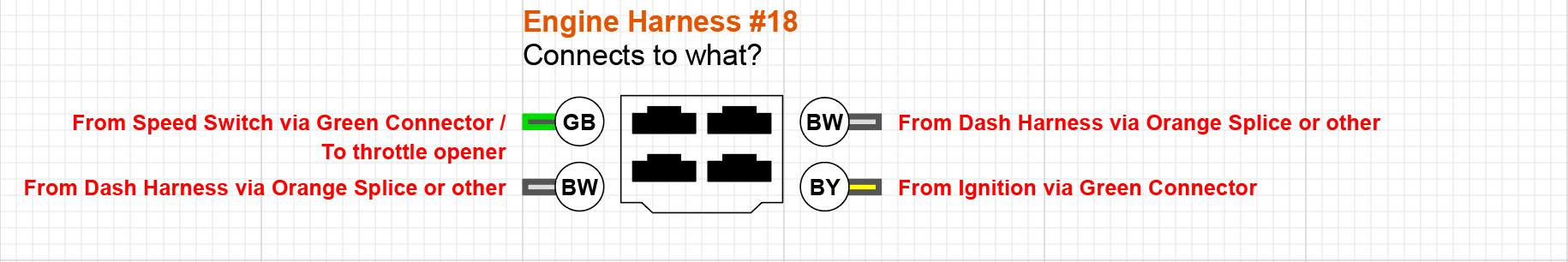
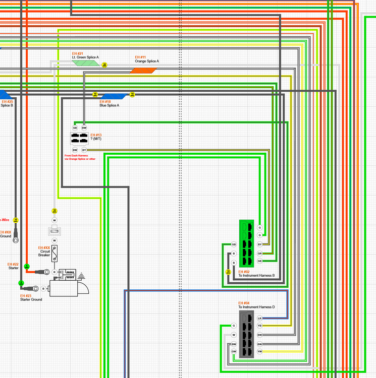
 @SteveJ I have a theory: I am guessing that the two G wires that go into the 6-pin connector on an automatic are the ones that go to the neutral safety switch on a manual. I am also guessing that the BY wire coming off the orange splice is one of the two BW wires on your manual that goes to the 4-pin connector. On my harness that BY wire splices to wires terminating at the coil positive, the fuse box, the front electric fuel pump, The ignition switch, and the throttle opener switch. I believe the GB wire comes off the green connector and ends up in that 4-pin connector somehow (either directly or via a splice). If all of this is correct, then this should be right: It would look like this in my diagram: We just need to figure out whats up with those BW wires.
-
Yeah, the connector I am looking for information on is the one on the Engine harness labeled 18 in the FSM. It should be in the same position on the manual harness as the Seatbelt relay on the Automatic harness, based on what is in the FSM illustration. I need to know what it connects to and where the two BW wires are coming from. If possible, I would love to know whether any of the four wires in that connector are spliced to something else, but I understand that is a long shot request.
-
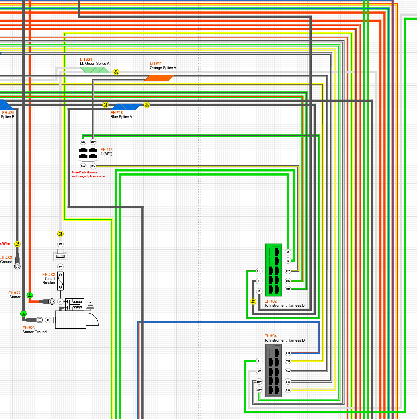
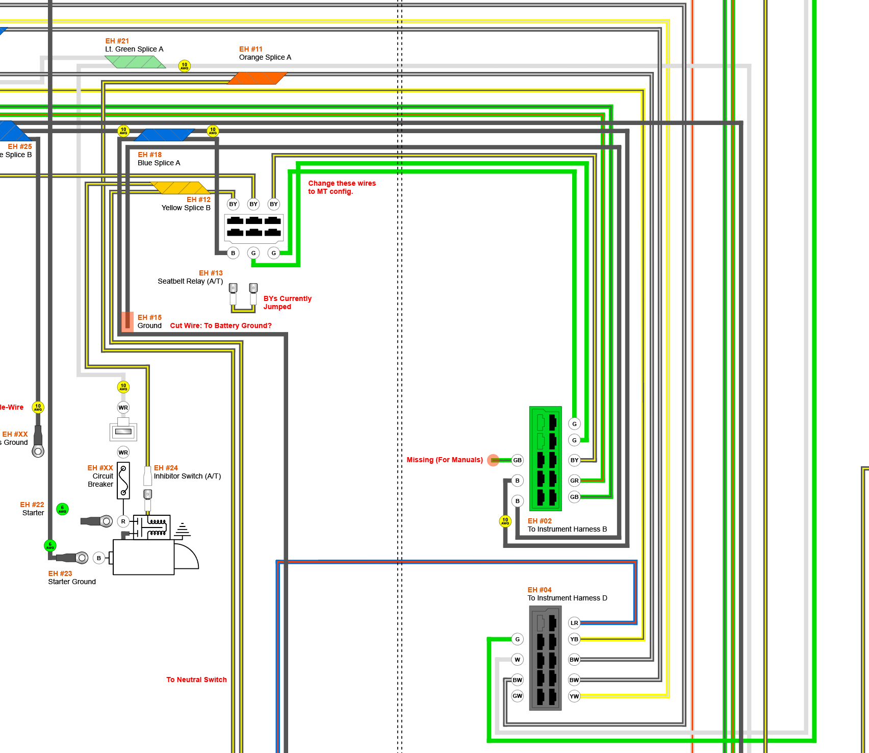
Thanks, but the full diagram from Eurodat is what I started with. These specific things aren't covered in it. Here is a drawing showing how the wires in my harness are routed from the green connector to the seatbelt switch: Notice that I have two BY wires going to my neutral switch, not green, and they come out of the seatbelt switch, not the green connector. If I understand you correctly, on the manual cars the green wires bypass the 4-pin connector and go straight to the neutral safety switch. Now that I think about it, the inhibitor switch on automatic cars replaces the neutral safety switch, so I have a flaw in my diagram for that. @SteveJ what does the 4-pin connector plug into since there’s no seatbelt relay? I am assuming the green connector's BY wire and GB wire (marked as missing in the drawing above) go to that 4-pin connector. If the BW wires merge somewhere into one wire I have no idea where that BW wire would come from. --- And it sounds like that BY wire on the blue connector I was asking about just isn’t really there since neither of us have it on our harnesses.


-
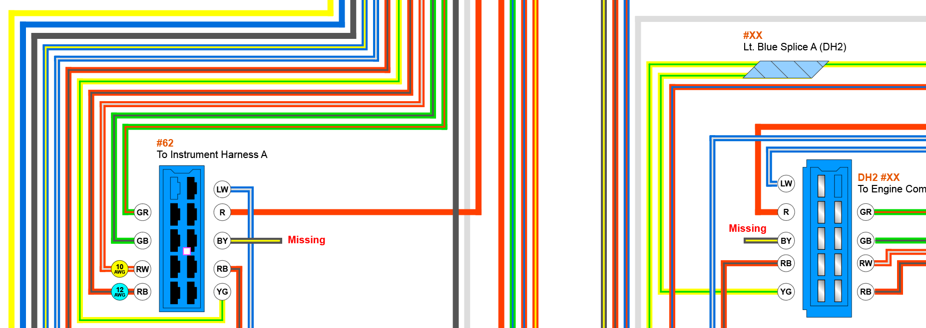
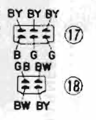
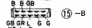
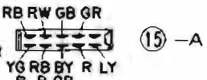
I have been working on creating a comprehensive diagrams so I can rebuild all of my wiring and I could really use some help with the last couple of details. Context: The previous owner sold me the car largely disassembled so I have had to chase all of the wires and connectors and figure out what they go to. In the process of doing that I discovered that my engine harness is for an automatic, but I have a manual car. There are also a couple of wires that were snipped. The first thing I need to understand is what one of the cut wires is for. It's a thin black wire (approximately 14 or 16 AWG) and comes out of the main trunk of the harness near the Seatbelt Relay connector. I traced it to the top left pin in the green connector (15B on page BE-2 of the FSM), which corresponds to a wire that is missing on my dashboard harness. This makes me think these wires are dedicated to the automatic cars. The next thing I need to understand is how the manual harness is different from the automatic harness for this year. I already figured out how the throttle opener solenoid wires are different, but I could use help with understanding the wires that go to the 4-pin connector that replaces the 6-pin connector for the seatbelt relay. The 6-pin connector wires are BY, BY, BY, B, G, G (#17 on page BE-2 in the FSM) and the wires for the 4-pin connector are GB, BW, BW, BY (#18 on page BE-2 of the FSM). I am pretty sure the GB wire on the manual is for the throttle opener solenoid and connects to the speed switch on the speedometer. I assume the BY wire on the manual replaces the third BY on the automatic. I have no idea about the others. I would have assumed there was a green on in there but no. The last thing I need to figure out is what the BY wire on the blue connector goes to. It's the center pin on the bottom (#15-A on page BE-2 of the FSM). This is completely missing on my engine harness, but also on my dashboard harness, which leads me to believe it is specific to manual cars, just like the GB wite for the throttle opener. I would really appreciate help ironing these details out. It's the final roadblock on getting my wiring diagram done so I can start rebuilding it. Let me know if are details I should add that would help.
-
1973 240z Climate Control Face Harness (24026 N3300) Inventory Position Component Connector Color Connector Style Direction # of Pins # of Wires Sample Wire Color Min. Feet of Wire Needed Wire Gauge 1 Heater Fan Blower Switch Harness White Nylon Male 3 2 Black [See Ground] 14 AWG – – – Red w/ Blue [See Red Splice A] 14 AWG 2 Red Splice A N/A N/A N/A 4 Red w/ Blue 1 (from Heater Fan Blower Switch Harness) 14 AWG Red w/ Blue [See Climate Control Light A] 14 AWG Red w/ Blue [See Climate Control Light B] 14 AWG Red w/ Blue [See Fan Switch Light] 14 AWG 3 Climate Control Light A Black Bulb N/A 1 1 Red w/ Blue 1 (from Red Splice A) 14 AWG 4 Climate Control Light B Black Bulb N/A 1 1 Red w/ Blue 1 (from Red Splice A) 14 AWG 5 Ground Black Fork N/A 1 1 Black 1 (from Heater Fan Blower Switch Harness) 14 AWG 6 Fan Switch Light Black Bulb N/A 1 1 Red w/ Blue 2 (from Red Splice A) 14 AWG
-
1973 240z Heater Fan Blower Switch Harness (27155-E4400) Inventory Position Component Connector Color Connector Style Direction # of Pins # of Wires Sample Wire Color Min. Feet of Wire Needed Wire Gauge 1 Blower Switch White Nylon Male 6 6 Black [See Yellow Splice A] 12 AWG Red [See Blue Splice A] 12 AWG Blue w/ White [See Climate Control Face Harness] 14 AWG White [See Blower Motor Resistors] 12 AWG Green [See Blower Motor Resistors] 12 AWG Yellow [See Blower Motor Resistors] 12 AWG 2 Blue Splice A N/A N/A N/A 4 Red 1 (from Blower Switch) 12 AWG Red [See Blower Motor Resistors] 14 AWG Red [See Climate Control Face Harness] 14 AWG Red [See Blower Power In] 12 AWG 3 Yellow Splice A N/A N/A N/A 2 Black 1 (from Blower Switch) 12 AWG Black [See Ground] 12 AWG Black [See Blower Motor Resistors] 12 AWG 4 Ground Black Fork N/A 1 1 Black 1 (from Yellow Splice A) 12 AWG 5 A/C Power Clear Bullet Female 1 1 Blue [See Blower Motor Resistors] 14 AWG 6 Blower Power In Clear Bullet Male 1 1 Red 2 (from Blue Splice A) 12 AWG 7 Climate Control Face Harness White Nylon Female 3 2 Red 2 (from Blue Splice A) 14 AWG – – – Blue w/ White 2 (from Blower Switch) 14 AWG 8 Blower Motor Resistors White Nylon Female 6 6 White 2 (from Blower Switch) 12 AWG Red 2 (from Blue Splice A) 14 AWG Black 2 (from Yellow Splice A) 12 AWG Green 2 (from Blower Switch) 12 AWG Yellow 2 (from Blower Switch) 12 AWG Blue 1 (from A/C Power) 14 AWG
-
I have pulled everything out. It's on a table in my office. That photo was from another thread.
-
This whole exercise has been a series of forehead slapping moments. Today was another one, where I realized that the bullet connectors making a junction on the fuel sending unit harness are there for connecting a fuel pump, which explains why there is no connector for said fuel pump. Mine doesn't have this, but there should be blue tape holding them down, which we all know by now is the giant beacon Nissan supplied for all optional components: (Image Source) I went round and round on this, but then I realized that the blue tape meant "optional" so the corroded bullet connectors in my post from yesterday had to be the way they meant for us to connect an electric fuel pump. Anyway, here's the table for it: 1973 240z Electric Fuel Pump & Fuel Sender Unit Harness (24815-E8200) Inventory Position Component Connector Color Connector Style Direction # of Pins # of Wires Sample Wire Color Min. Feet of Wire Needed Wire Gauge 1 Body Harness A White Nylon Male 2 2 Black [See Yellow Splice A] 14 AWG Yellow [See Sending Unit] 14 AWG 2 Body Harness B White Nylon Male 1 1 Green [See Fuel Pump] 12 AWG 3 Chassis Ground Black Ring N/A 1 1 Black [See Yellow Splice A] 12 AWG 4 Yellow Splice A N/A N/A N/A 3 1 (from Body Harness A) 14 AWG 1 (from Chassis Ground) 12 AWG [See Yellow Splice B] 12 AWG 4 Yellow Splice B N/A N/A N/A 3 2 (from Yellow Splice A) 12 AWG [See Fuel Pump] 12 AWG [See Sending Unit] 14 AWG 6 Fuel Pump Clear Bullet Male 1 1 Black 1 (from Yellow Splice B) 12 AWG Clear Bullet Female 1 1 Green 3 (from Body Harness B ) 12 AWG 7 Sending Unit Black Ring N/A 1 1 Yellow 3 (from Body Harness A) 12 AWG Black Ring N/A 1 1 Black 1 (from Yellow Splice B) 14 AWG
-
Thanks for the additional details! Here are a couple more tables… 1973 240z Fuel Pump Harness A (24032-N3300) Inventory Position Component Connector Color Connector Style Direction # of Pins # of Wires Sample Wire Color Min. Feet of Wire Needed Wire Gauge 1 Engine Harness White Nylon Male 6 5 Yellow [See Voltage Regulator] 14 AWG Yellow [See Voltage Regulator] 14 AWG – [See Voltage Regulator] 14 AWG Black w/ White [See Voltage Regulator] 14 AWG Yellow w/ Black [See Voltage Regulator] 14 AWG Black [See Voltage Regulator] 14 AWG 2 Voltage Regulator White Nylon Female 6 5 Black 1 (from Engine Harness) 14 AWG Yellow w/ Black 1 (from Engine Harness) 14 AWG Black w/ White 1 (from Engine Harness) 14 AWG – – – Yellow 1 (from Engine Harness) 14 AWG Yellow 1 (from Engine Harness) 14 AWG [See Fuel Pump Junction B] 14 AWG 3 Fuel Pump Clear Spade Female 1 1 Black w/ Yellow [See Fuel Pump Junction A] 14 AWG 4 Fuel Pump Junction A Clear Spade Female 1 1 Black w/ Yellow 4 (from Voltage Regulator) 14 AWG 5 Fuel Pump Junction B Clear Bullet Female 1 1 Yellow 3 (from Fuel Pump) 14 AWG 1973 240z Fuel Pump Harness B (24034-N3300) Inventory Position Component Connector Color Connector Style Direction # of Pins # of Wires Sample Wire Color Min. Feet of Wire Needed Wire Gauge 1 Dashboard Harness White Nylon Male 2 2 Green [See Fuel Pump Relay] 12 AWG Black w/ White [See Fuse Loop] 12 AWG 2 Fuse Loop White Nylon Female 2 2 Green [See Heater / Choke Relay] 12 AWG Black w/ White 1 (from Dashboard Harness) 12 AWG 3 Fuel Harness B White Nylon Male 2 2 Green [See 20 Amp Fuse] 12 AWG Black w/ White [See 20 Amp Fuse] 12 AWG 4 20 Amp Fuse White Nylon N/A 2 2 Green 1 (from Fuel Harness B) 12 AWG Black w/ White 1 (from Fuel Harness B) 12 AWG 5 Fuel Pump Relay White Nylon Female 6 5 – – – – – – Black w/ White [See Fuel Pump Junction A] 12 AWG Green [See Heater / Choke Relay] 12 AWG Green 5 (from Dashboard Harness) 12 AWG Black [See Heater / Choke Relay] 14 AWG [See Ground] 14 AWG 6 Ground Black Ring N/A 1 1 Black 1 (from Fuel Pump Relay) 7 Heater / Choke Relay 4 4 Green 5 (from Fuse Loop) 12 AWG Yellow [See Fuel Pump Junction B] 12 AWG Black 1 (from Fuel Pump Relay) 14 AWG Green 1 (from Fuel Pump Relay) 12 AWG 8 Fuel Pump Junction A Clear Spade Male 1 1 Black w/ White 2 (from Fuel Pump Relay) 12 AWG 9 Fuel Pump Junction B Clear Bullet Male 1 1 Yellow 2 (from Heater / Choke Relay) 12 AWG
-
Thanks! I’m going to delete the points and move to electronic ignition, but good to know about the others. In a quick google search I’m seeing a coil condenser and a voltage regulator condenser. Are these the other two, or is the coil condenser the same as the distributor condenser? I’m also seeing one for automatic transmissions.
-
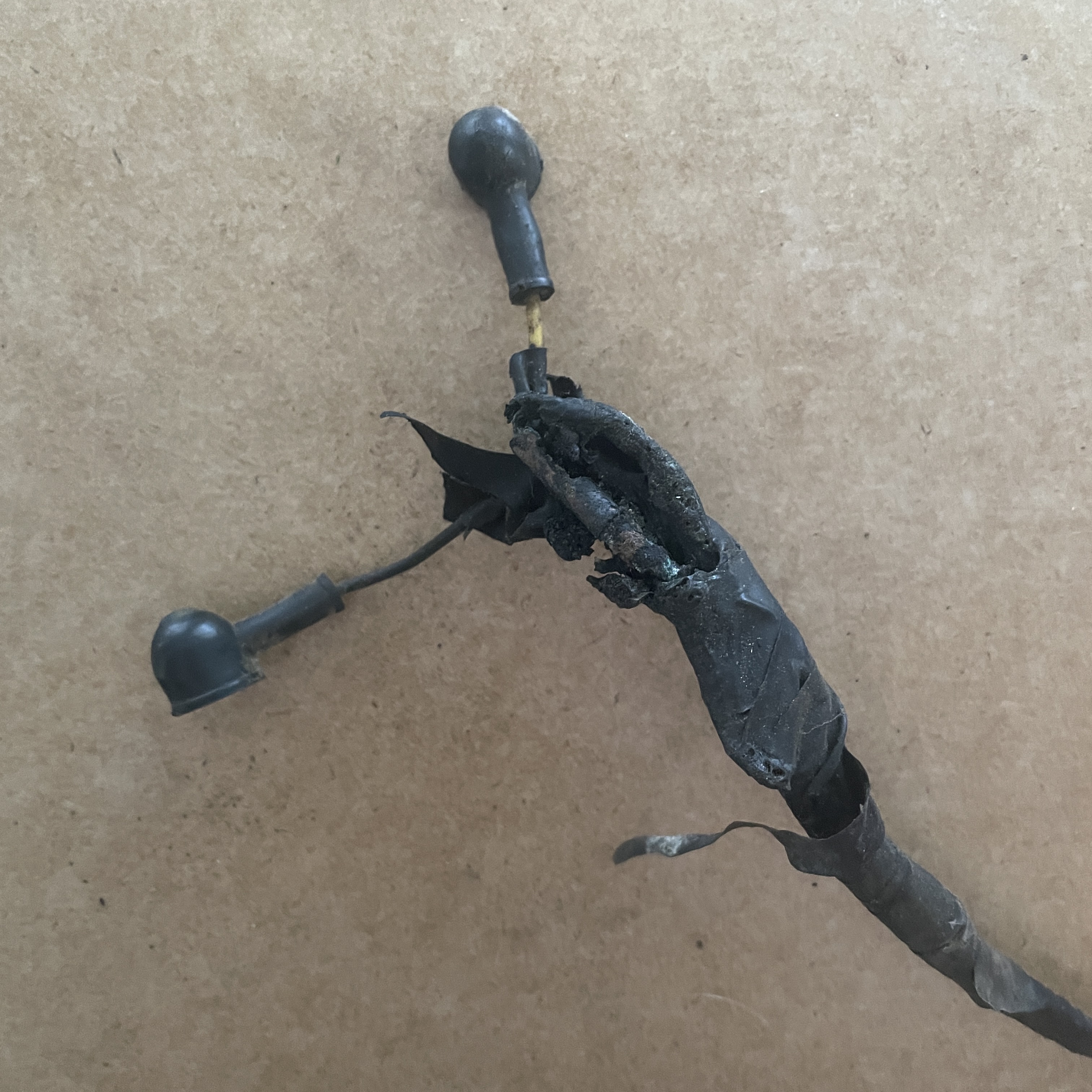
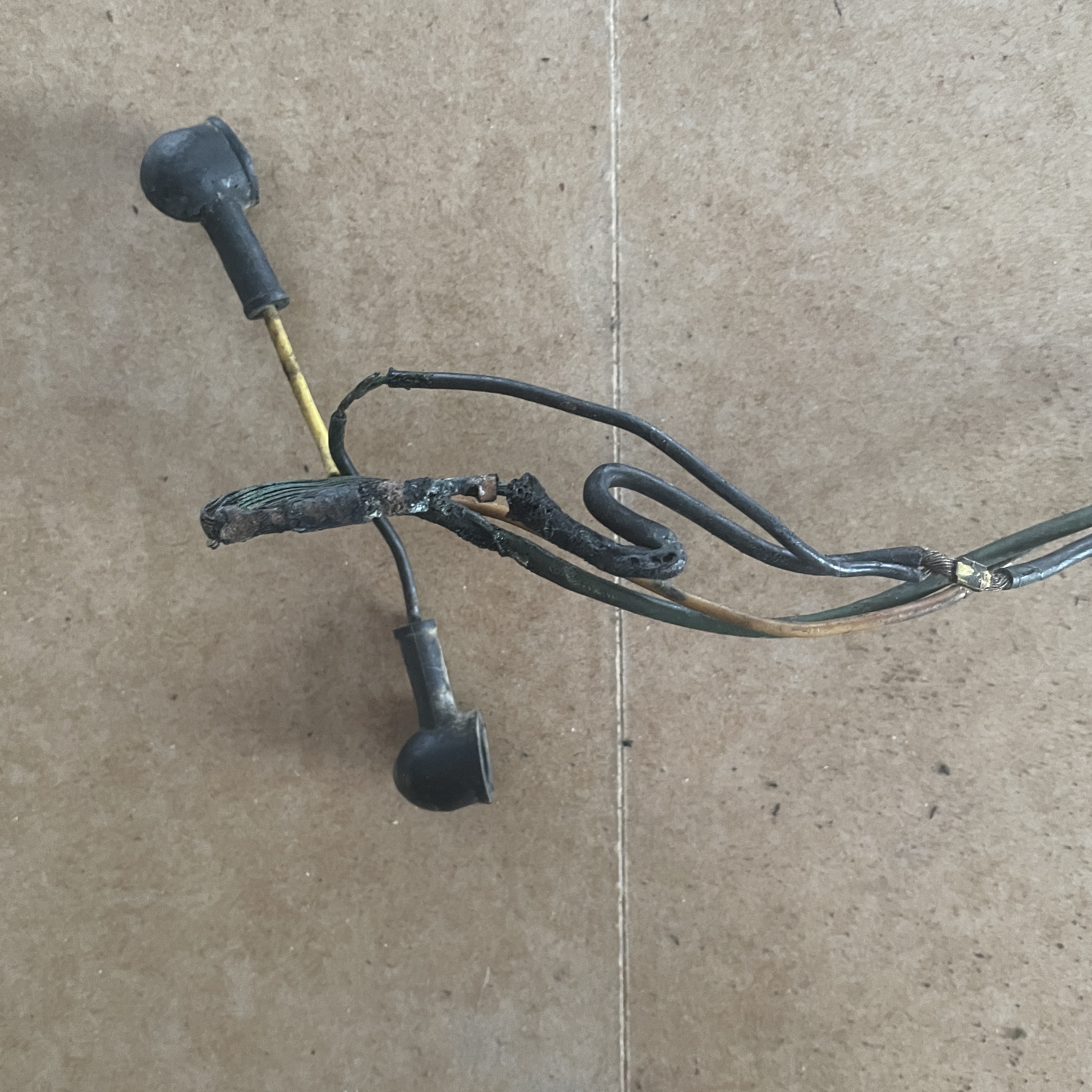
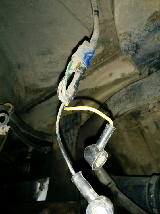
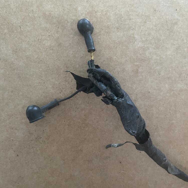
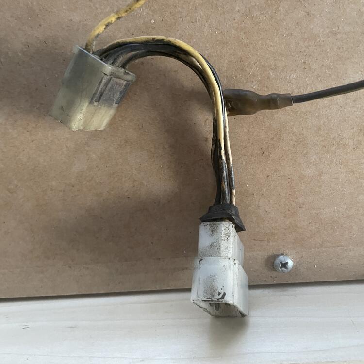
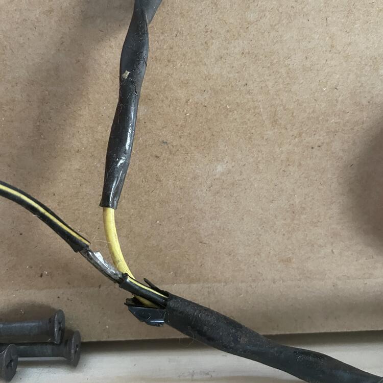
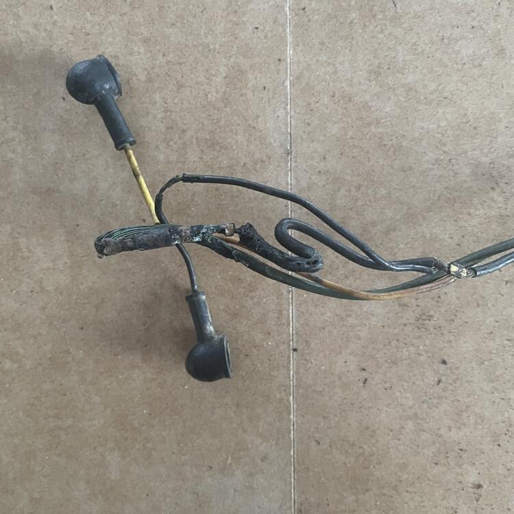
Someone asked me why I’m making all new harnesses from scratch rather than rebuilding what I have, and I think these photos answer that question. I have problems like these throughout all of my wiring across the entire car:
-
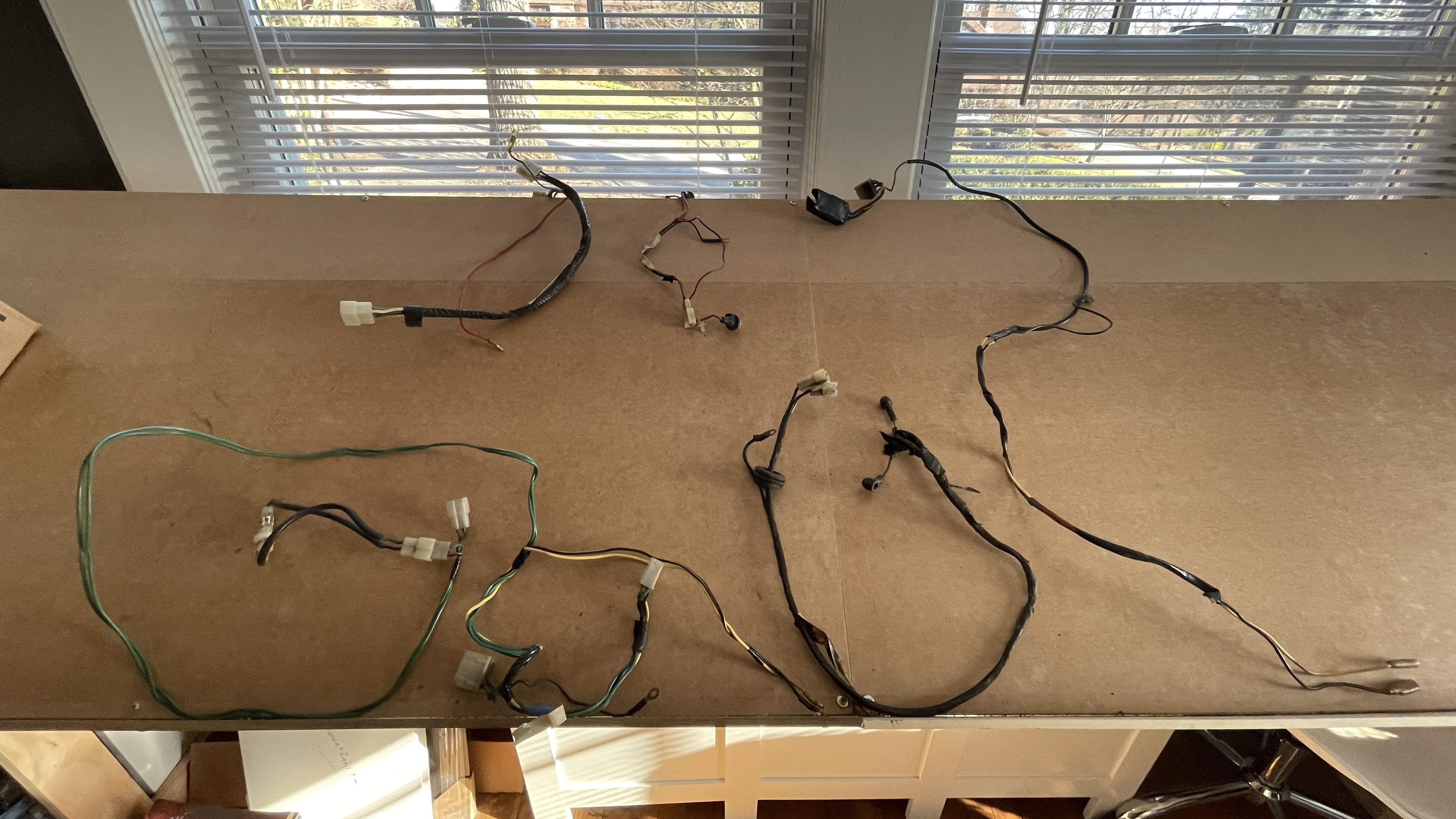
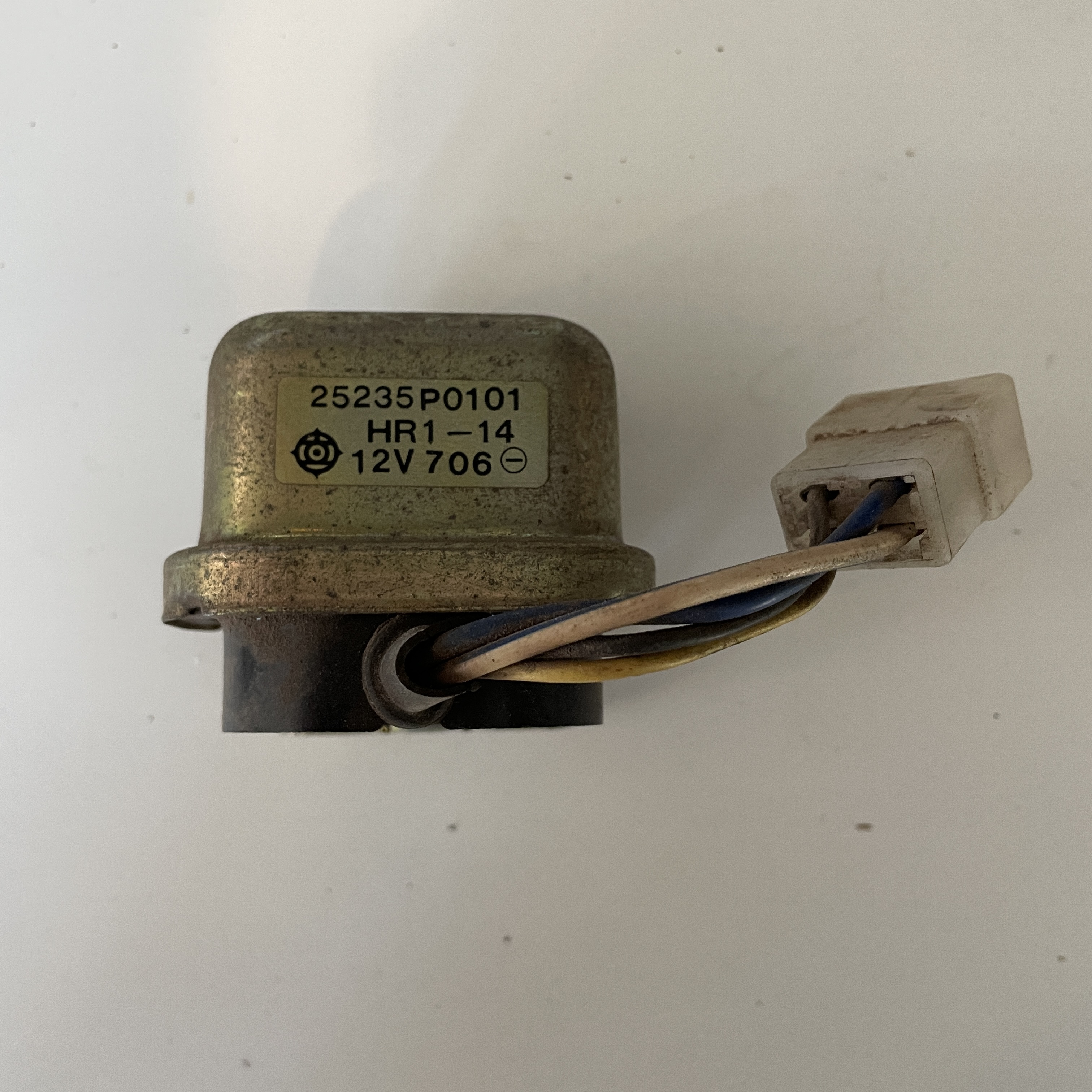
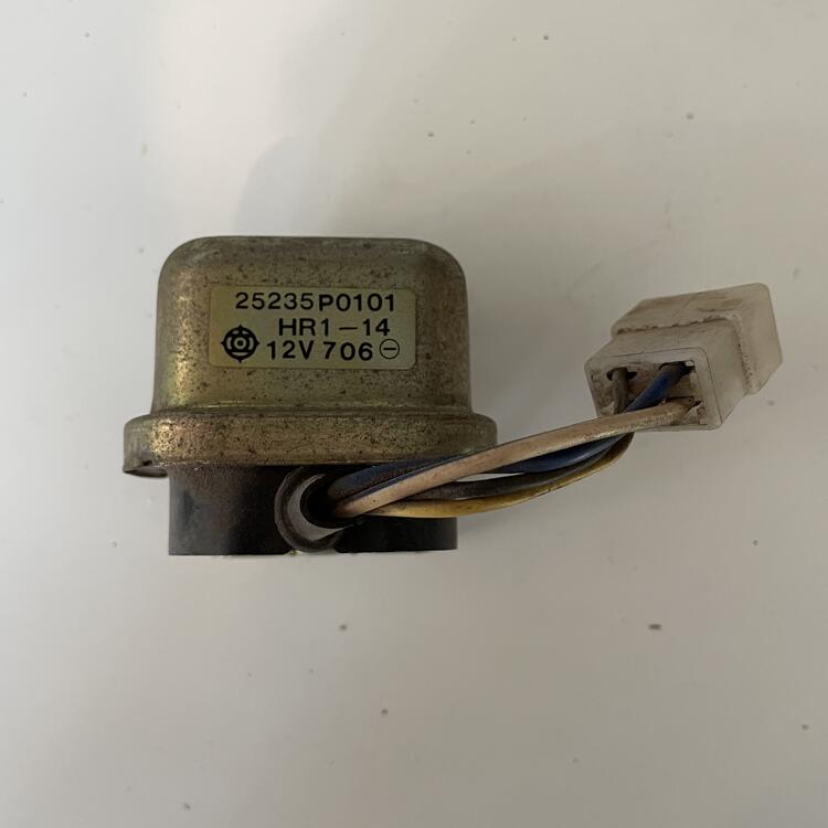
I unearthed another box of wiring harnesses I had buried in my basement which has shed light on some things above, specifically the Fuel Pump Relay and how that fits into the rest of things. This thread started by @conedodger prompted me to look for the harnesses that were added in late 1973 shown in the illustration below supplied by @Carl Beck: So here's what I found: Clockwise from far right, they are… Fuel Pump Harness A (PN 24032-N3300) Electric Fuel Pump & Fuel Sender Unit Harness (PN 24815 E8200) Fuel Pump Harness B (PN 24034 N3300) Fan Blower Switch Harness (PN 27155 E4400) Climate Control Face Harness (PN 24026 N3300) So it looks like the one thing I am missing is Relay A (PN 25235 P0100) from the illustration @Carl Beck provided, which I have seen labeled as a heater relay or an Auto Choke Relay, but seems NLA like all the others. Should be fun trying to scrounge this, but first I need to add these 5 harnesses to my diagram and spreadsheets.

-
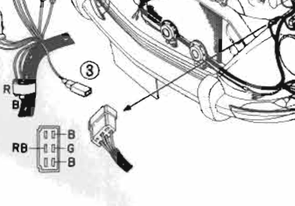
I'm almost certain the G and B wires are for the Thermostat Relay. The FSM indicates there should be 2 B wires and an RB wire as well, which come off the distributor and the distributor relay. I am missing that connector in my AT harness, so that has to be it. Here it is illustrated on page BE-2 of the FSM:
-
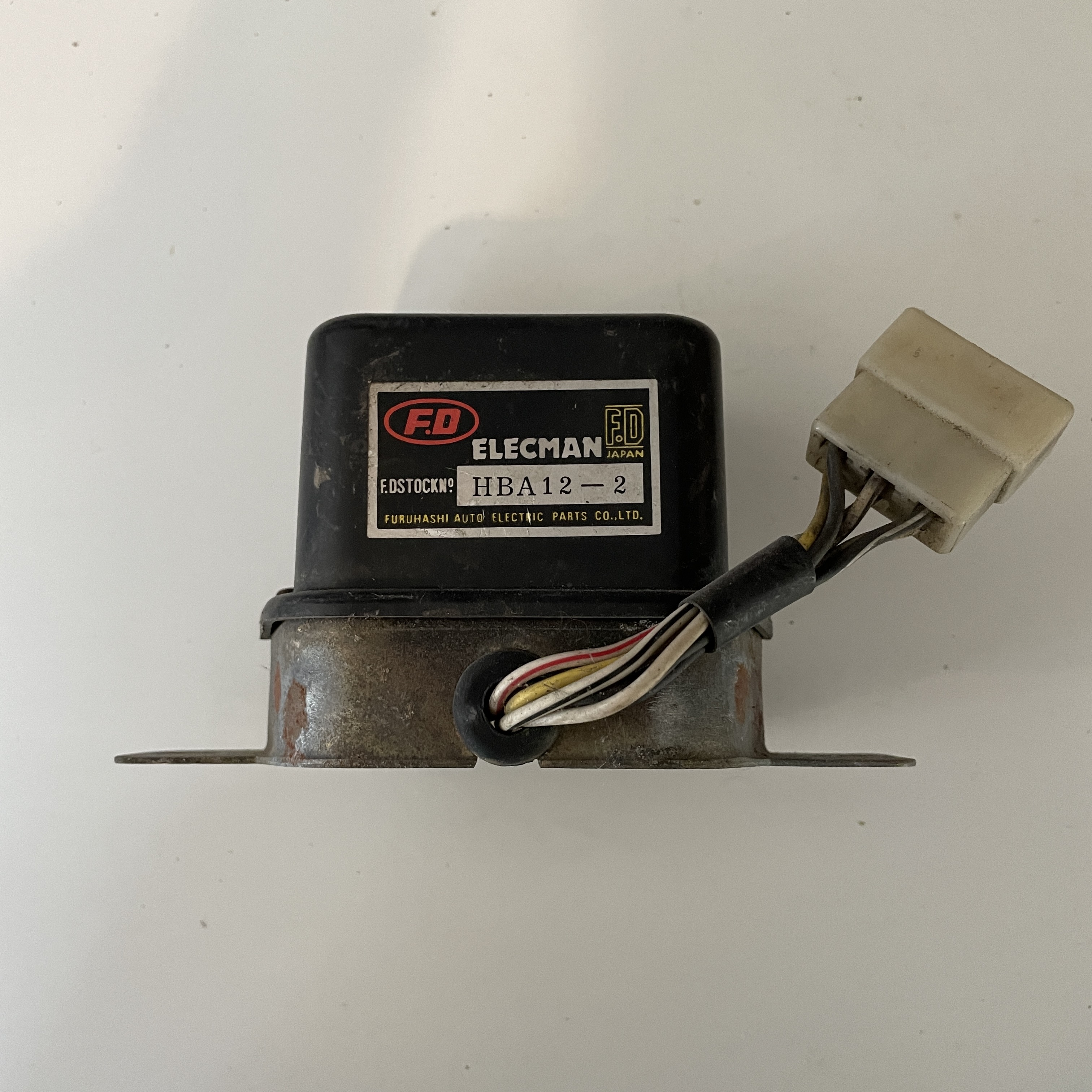
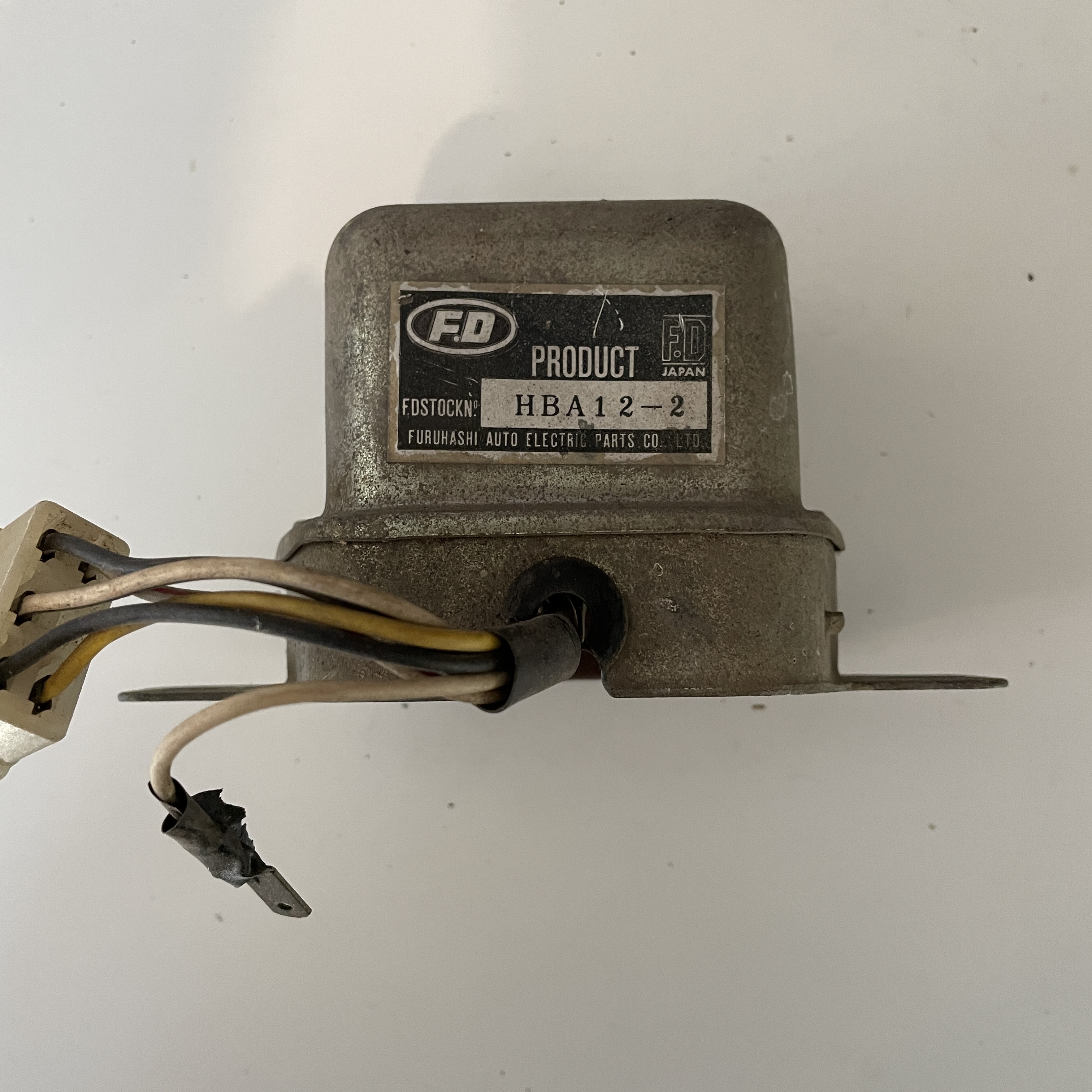
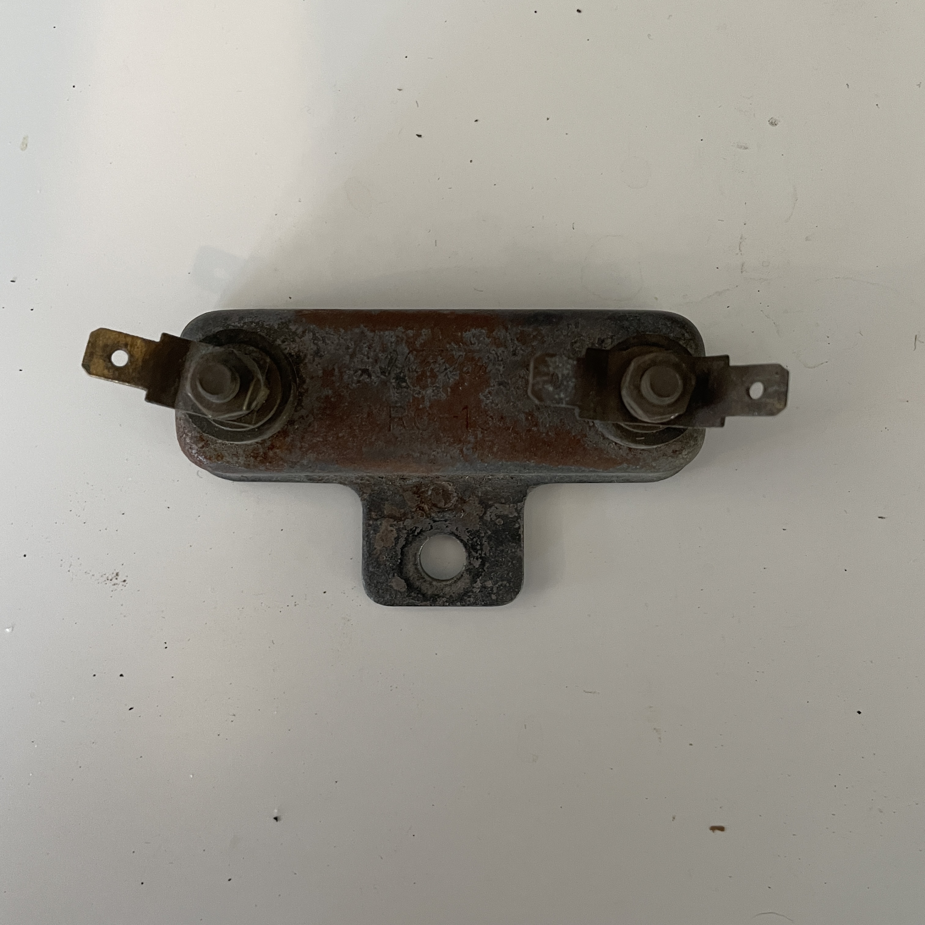
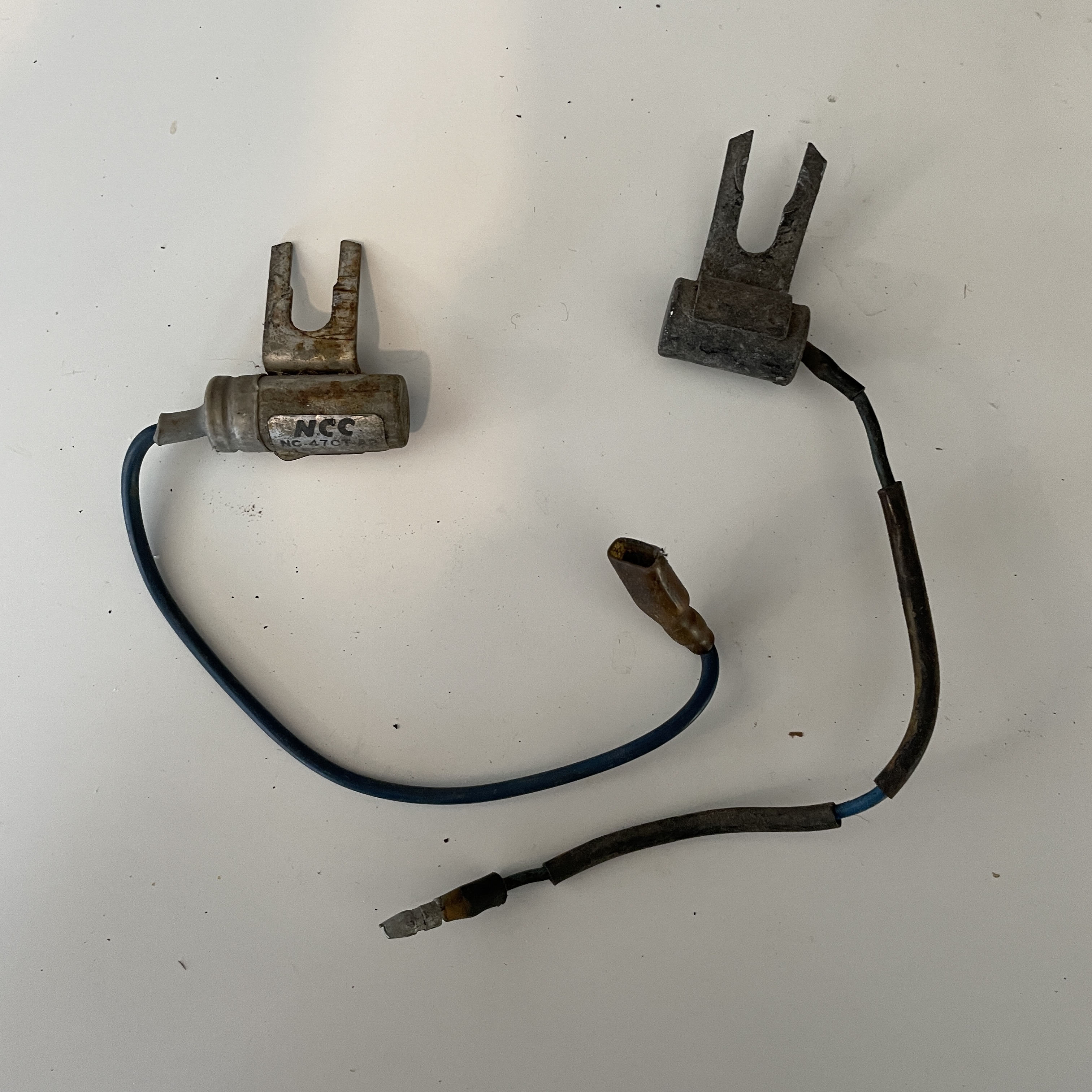
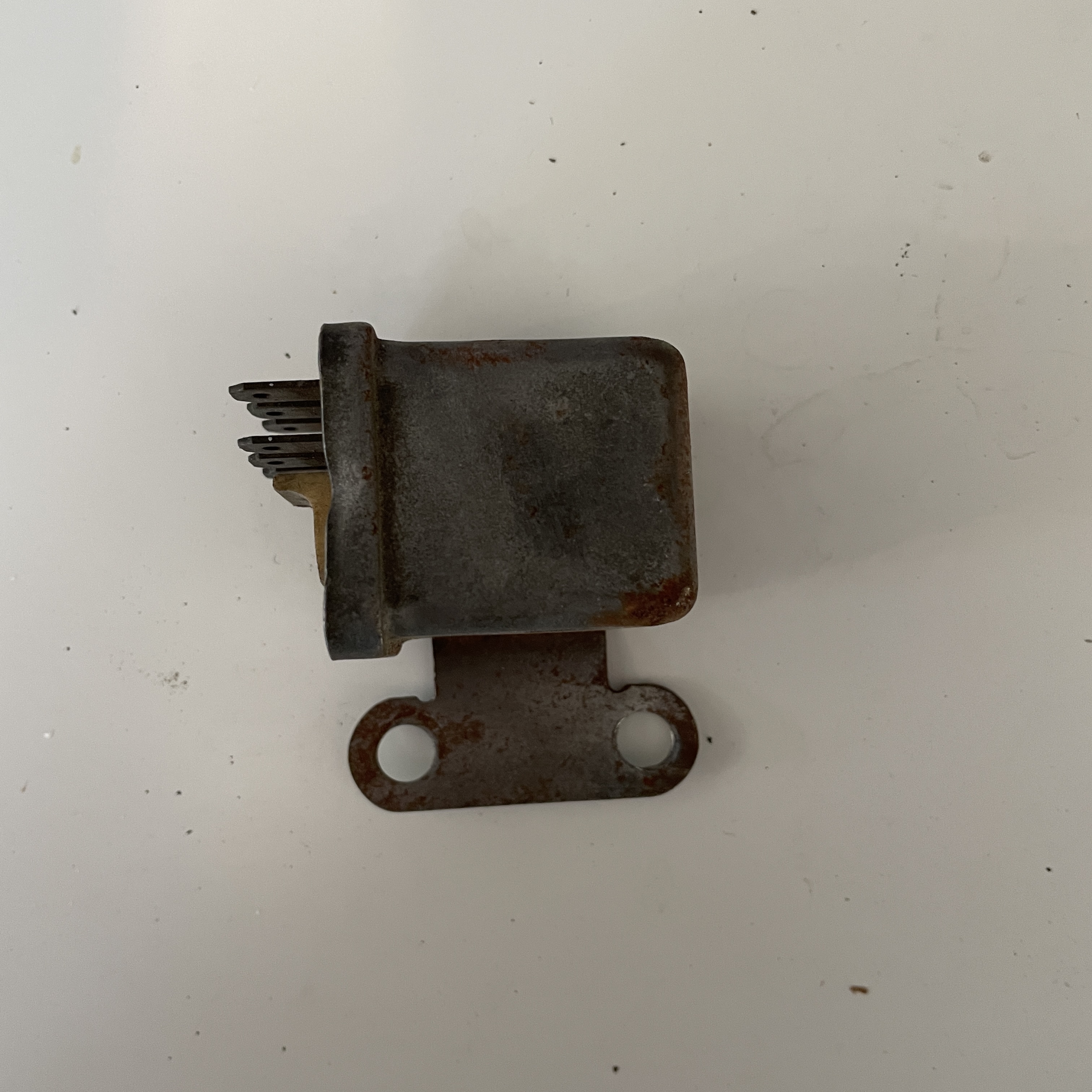
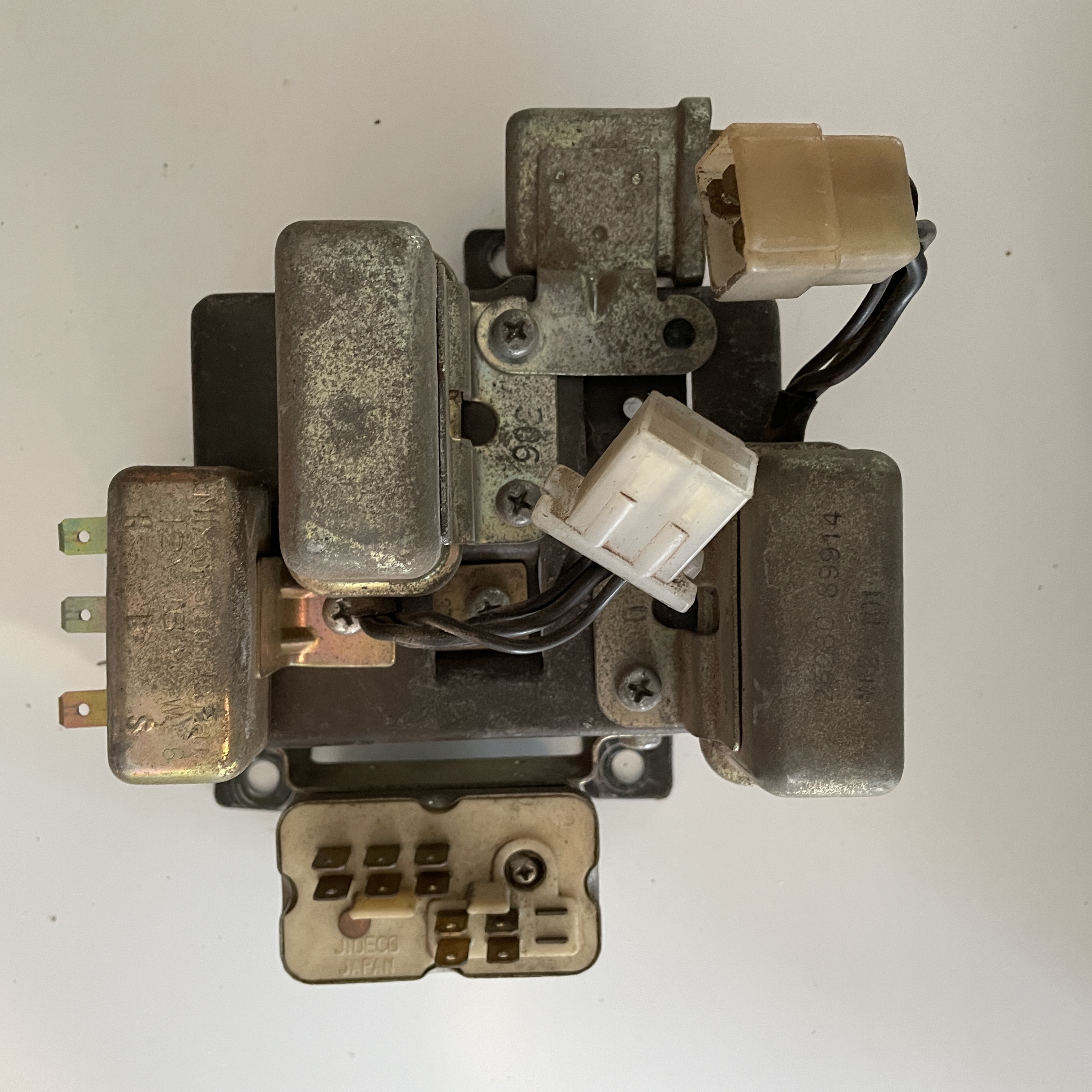
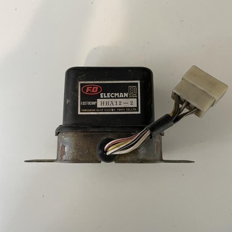
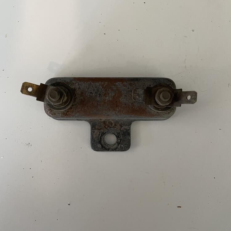
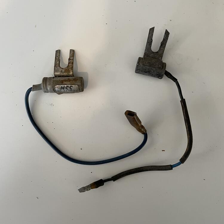
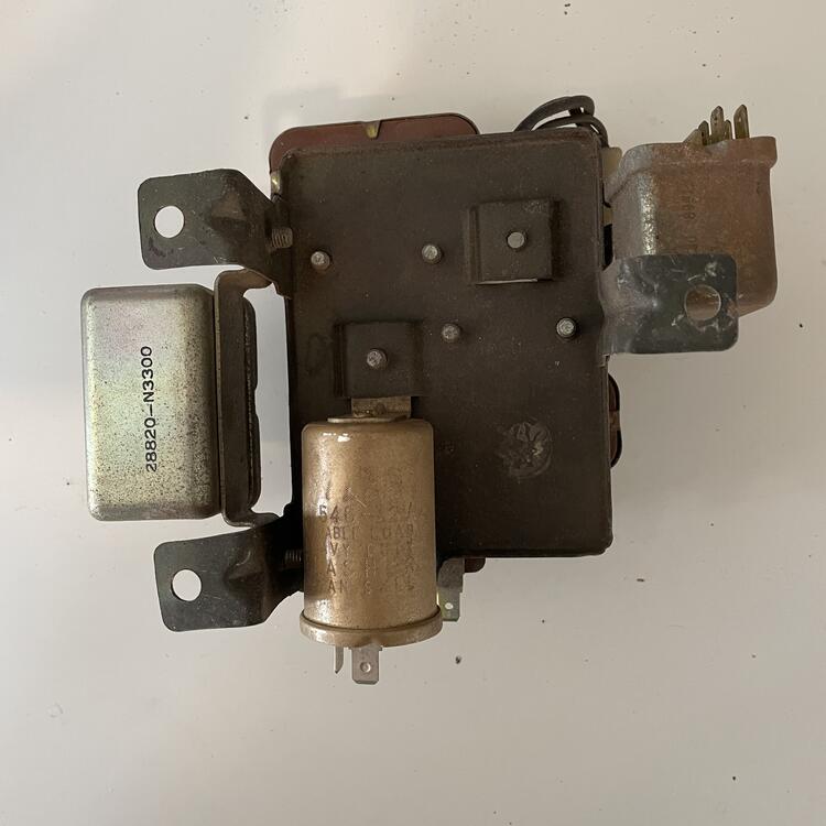
Next to last step (other than identifying those damned cut wires) is to map the relays to the harnesses, so I went through my pile o' parts and this is what I have: Voltage Regulator #1 - Elecman HBA12-2 by F.D. Japan, 6 wires (Y, W, WR, BW, WB, and Voltage Regulator #2 - Product HBA12-2 by F.D. Japan, 6 wires (Y, W, WR, BW, WB, and Electric Fuel Pump Relay - HR1-14 12v 706 (PN 25235 P0101) by Hitachi Ballast Resistor - RC-15 by Hanshin Two different distributor condensers - The longer one is a NC-47CT-A2 150v 47m capacitor by NCC. The other is illegible. The front of my relay bundle - Clockwise from bottom: Windshield Wiper Relay by Jideco (PN 28820-N3300) 3-pin 12v 15A Horn Relay by Miyanmoto Japan 4-pin Defroster Relay 6-pin Fuel Pump Relay by Jideco (PN 25230 89915) 3-pin MR2-101 Accessory Relay by Jideco (PN 25230 39914) The rear of my relay bundle has a HF546A 12v Heavy Duty Flasher Relay by Niles And another 6 pin relay with no markings by Jideco. Could be a Choke or Headlight Relay, or another Fuel Pump Relay as above.


-
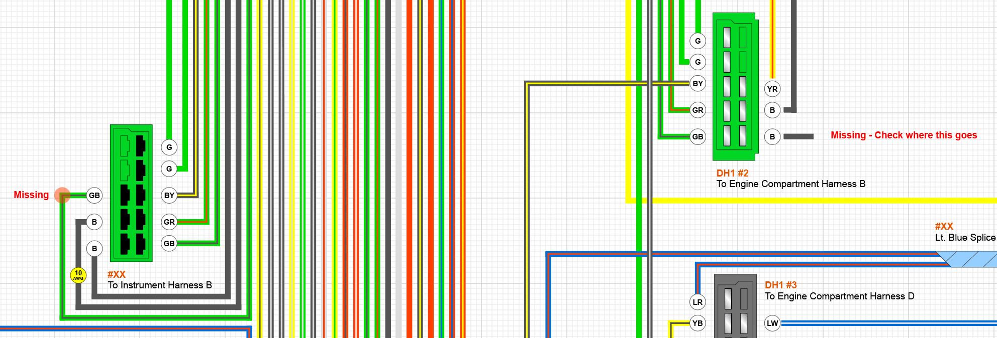
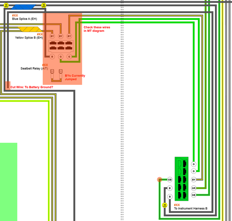
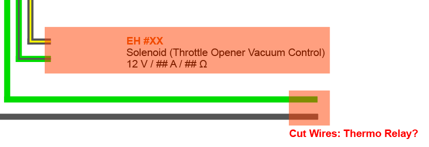
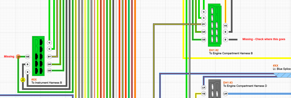
I've made major progress on my wiring diagram. I didn't finish the fuel harness for the rear of the car because I don't have one handy, but I don't think it is that important for moving forward. I do have a handful of mysteries, though. I think they are mostly caused by my having an engine harness for an automatic, but I am not sure. I will try comparing the two wiring diagrams in the morning. In the mean time, maybe someone knows the answers… 1. On the two blue 10-pin connectors that join the dashboard harness to the engine harness, I have a Black wire with a Yellow stripe missing from both sides. It's in the FSM on pages BE-2 and BE-3 but the only thing I am seeing in the actual diagram (page BE-5) is the Black wire with a Yellow stripe that goes to the water tank. In my harness that wire is actually Black with a White stripe, and most of the Black wires with a Yellow stripe are related to the seatbelt relay, the throttle opener, and the thermo relay. 2. On my engine harness I have a Black wire that has been cut, which I have labeled "battery ground?" in the drawing below, but that probably isn't right. It comes out of the main trunk of the harness near the seatbelt relay for the automatic car and runs back to the green 10-pin connector that joins the dashboard harness to the engine harness. That wire is completely missing on the dashboard side. 3. I have three cut wires and a missing wire that I am pretty sure are related to the thermo switch and the throttle opener, but I want to be entirely sure. I am pretty certain that the Black wire with a Yellow stripe, which has been cut, goes to the throttle opener. The Green and Black wires, also cut, branch from the main trunk of the harness at the same point as the Black wire with a Yellow stripe, near the distributor in the front left corner of the engine bay. On the other end, the Green wire connects to the Voltage Regulator, the Distributor Condenser, and ultimately the fuel pump in the back of the car. The Black wire connects to all of the other black wires in the Engine Harness going to the lights, Alternator, Starter, and the Intermittent Relay. In retrospect, I think these two wires go to the Thermo Switch and control the EGR vacuum control. The missing one is the Green wire with a Black stripe, which could be one of the other three and is just mislabeled in the FSM, or could be entirely missing. I'm pretty sure it's missing because there should be a GB wire going to the green 10-pin connector that connects to the dashboard harness in the pin highlighted with the red circle below. This GB wire would connect to the Yellow wire with a Red stripe on the dashboard harness, which we have previously discussed as being for the throttle opener. In the FSM this is shown going to the Relay Assembly Type K24 (Throttle Opener Relay), but on the manual cars. 4. I have three items in the FSM wiring diagram that I am missing in my own because I don't have any connectors remaining to identify. Here's what's in the FSM: Solenoid Valve Assembly (EGR Vacuum Control) - Different from the Throttle Opener Vacuum Control Thermo Switch Assembly (Temp Sending Switch) - This is probably two of the cut wires above Relay Assembly Type K5 (Distributor Relay) - Possibly unimportant since I am switching to an e12-80 Inhibitor Switch - Possibly what I have labeled as the Seatbelt Relay, which is what the FSM has that connector labeled on page BE-2

-
Cool. Thanks for the tip.
-
Question for the room: is it better to put the windshield in before or after other things? I feel like I could put my windshield in now, but I have this hazy feeling that some thing’s might be easier to instal with it out. Conversely, I feel like installing the windshield with other things in the car (dashboard) might make it harder.
-
Ooooh, duh. Okay, yeah. Not sure why I didn’t realize that. I‘ve gone around a couple of times on the topic of the tach mod. Some people insist that the tach needs to be upgraded and some people insist that it doesn’t. Either way I will work this out later in the process and proceed with the engine harness.
-
Now that I am almost done verifying (and fixing) my documentation of the two dashboard harnesses I just have one last thing to do one the dash: figure out where the resistor for the Tach is supposed to be. I just traced everything from the Tach and Ignition Switch plugs on the dashboard harness all the way to the ballast resistor on the engine harness and I am not seeing one. I took a look at this thread and the photos that @zKars posted on page 2 look like it is located on the engine harness just inside the cabin, close to the colored connectors, but that's one of the 2,200Ω resistors on a 280Z: Unfortunately, I don't have anything even approximating this on mine. I thought maybe my dash is from a different year, but the FSM for the '72 shows a 0.5Ω resistor between the ignition and the tach. The '73 FSM shows a resistor wired up the same way, but does not indicate how many ohms of resistance if provides. I found a resistor on the 1974 FSM diagram and it is on the engine harness on a Blue wire, similar to the photo above, that runs to a splice to the Full-Transistor Ignitor Unit, and the Ignition Coil, but I am not sure this serves the same purpose. I'd like to figure out how it is supposed to be set up on the 1973 harnesses, but I also need to figure out what I should do for my final setup because I have a 280ZX distributor with a E12-80 Ignition box and I would like to make my regular 1973 tach work with it rather than doing a bunch of unnecessary modifications there, per @Zed Head's recommendation.
-
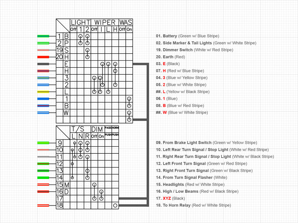
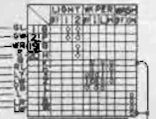
I updated the diagram for the Combination (Wiper) and Turn Signal Switches to match the samples I have on hand and the 1973 FMS: The Red text needs better labeling. I went with what is in the FSM where I could for now. Also, in my sample, #2 (Blue with a White stripe) is actually Yellow with a Blue Stripe. It changes to LW at the connector and goes to the Intermittent Relay.
-
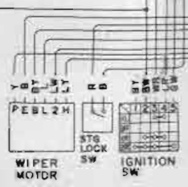
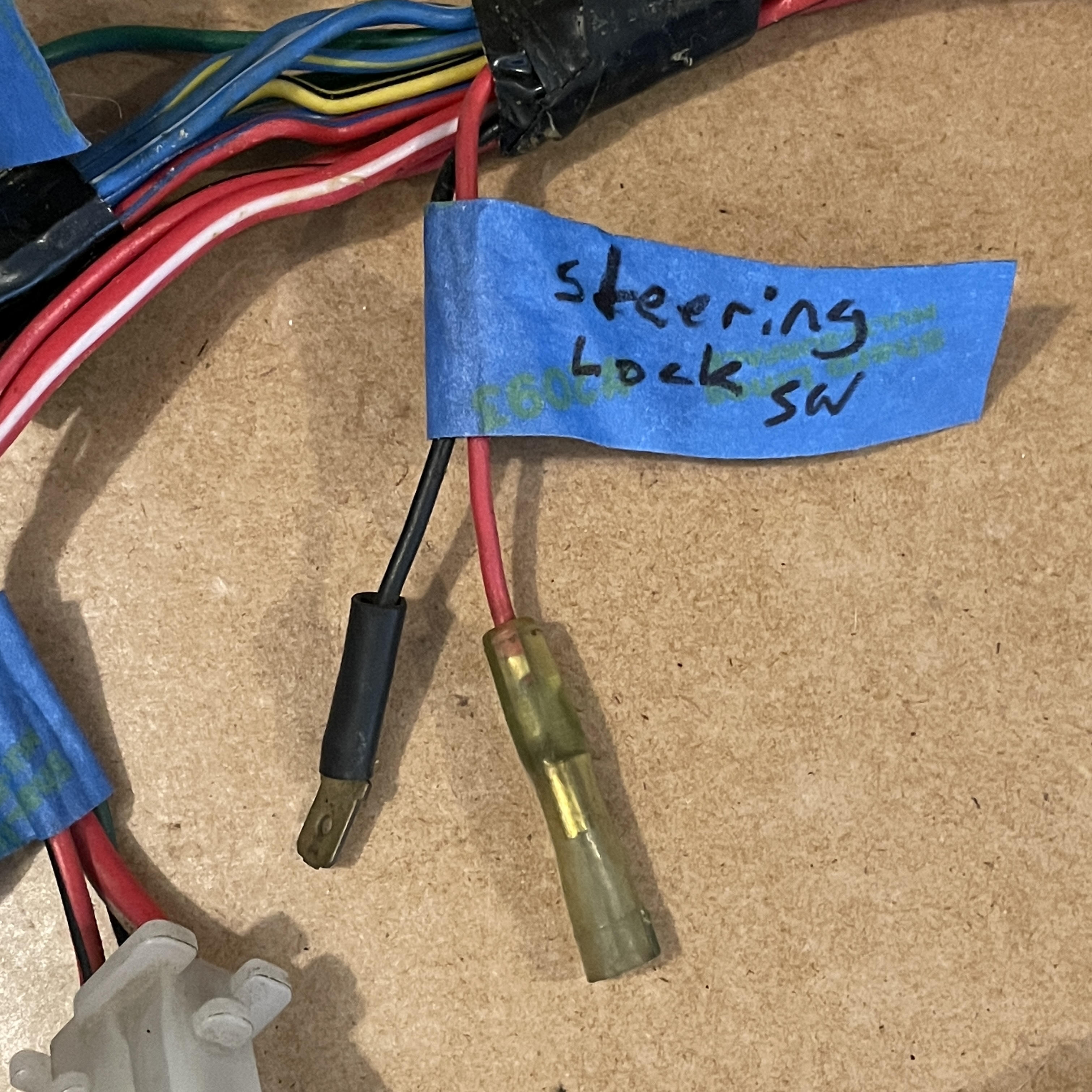
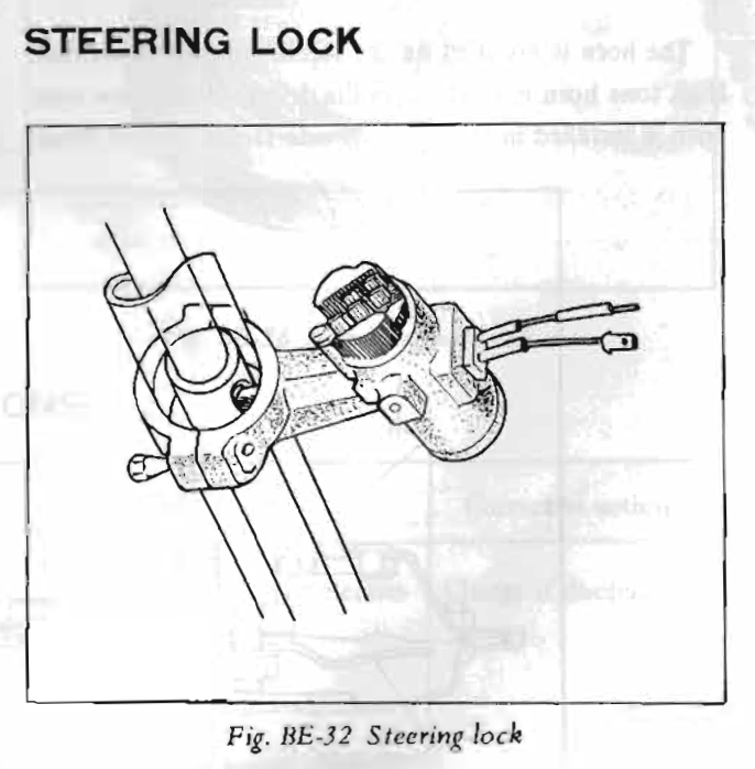
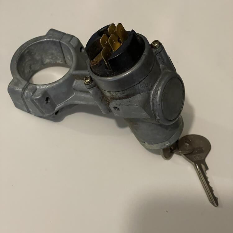
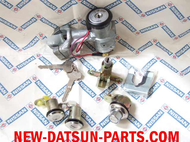
This post is just for documentation purposes and to put a bow on some things I have brought up over the last few days… I retraced the Red wire with a Blue stripe coming out of my wires switch and confirmed that it 100% does not go to the fuse box. It goes to the center pin on the 9-pin connector on Dashboard Harness 2 (the one with all of the lightbulbs on it). That center pin on the 9-pin connector on the harness goes to the black connector that connects to the Engine harness. Note: in the FSM this connector is white. The white one on my harness is black in the FSM. I verified this by the wires they contain and by the shapes of the connectors, which are unique. That pin on the black connector switches to a Blue wire with a Yellow stripe on the engine harness and goes to the 6-pin connector for the wiper motor. Also, there is no second buzzer in the wiring diagram in the 1973 FSM. Just the single 3-wire buzzer with the 3-pin connector, which I have accounted for. In the FSM, the "STG Lock SW" I keep bringing up has a Red wire that is spliced to a Re wire with a Blue stripe running to the left step light as well as some of the dashboard lights (map light, glove box light, room light) and ends at a 6-pin connector for the fuse block. That pin has a second Green wire with a Blue stripe that runs directly to position #2 on the wiper switch (after a color change to Green with White). The connector on the Fuse Block also swaps colors to Green with White ( ¯\_(ツ)_/¯ ). I already mentioned that the Black wire on the "STG Lock SW" runs directly to the left door switch. On page BE-23 of the FSM, it states, "The steering lock is combined with the ignition switch to a single unit which contains warning buzzer micro-switch for reminding the [driver] to lock the steering. The microswitch is connected to a warning buzzer." This corresponds to what @SteveJ has said. On the next page it mentions the ALR, which is not in any of the diagrams… The two wires I have in the harness go to this integrated steering lock. The reason I can't find it in my stuff is that I don't have one. I have one from an older car. Here's what the one for a 1973 240Z should look like (note the two wires coming off of it with spade connectors): And here is what I have (note the lack of the two wires): Here's a picture of a different version I found on new-datsun-parts.com, probably from an older year (note the plastic ring with the two wires, i.e. non-integrated steering lock): So, questions answered. I just need to find a 1973 ignition switch or the non-integrated one mine is missing for the problem to be solved. In other news, the Comb. Switch in the FSM for 1973 is pretty different from 1973 wiring diagram I downloaded from this site. First, the positions are only numbered for the first four wires (1, 2, 19, & 20). In the FSM, the wires from top to bottom are: GL (Labeled as Position 1) GW (Labeled as Position 2) WR (Labeled as Position 19) R (Labeled as Position 20) B RL LY LW YB L LR LW B (back side) B (back side) There are 14 lines running to the box denoting the Combination switch, with 12 color labels. There are 13 rows showing the jumpers in the switch and how the mechanisms route electricity to the wires. The 13th row is dedicated to one of the 2 black wires coming out the other side of the box to connect it to the TS switch, as discussed, and does not go to the GB wire going to the horn. When looking at my actual switches, there are 14 pins across 6 connectors on the wiper switch, two of which connect to each other. They are: 9-Pin Connector GL (Goes to Body Harness, Fog Light Switch, Radio, Rheostat, & Cigar & Hazard Fiber Optic Light Source) GW (Changes to GL and goes to Fuse Box, as mentioned above) RL (Goes to the Engine Harness where it changes to LY and goes to the Wiper Motor) LY (Goes to Engine Harness and terminates at the Intermittent Relay) LW (Goes to Intermittent Relay and splices to wires going to the Engine harness and ending at the water tank) L (Goes to Intermittent Relay) LR (Goes to Engine Harness and branches to the Wiper Motor and Reverse Light Switch on Transmission, but I need to verify this) YB (Goes to the Engine Harness where it changes to B and goes to the Wiper Motor) YL (Changes to LW at the connector and goes to the Intermittent Relay and the Engine Harness where it goes to the Wiper Motor) Spade Connector G (Splices to many other black wires that run to various dashboard & center console instruments, the Rear Window Defroster Relay, and the Engine harness, terminating at the Alternator) Bullet Connector #1 WR (Splices to WR or L wires going to Alternator, Defrost Relay, Fuse Box, Accessory Relay, Ignition Switch, Ammeter, etc.) Bullet Connector #2 R (Goes to the Fuse Block, then to the Engine Harness and ending at the Fog Lights) Bullet Connector #3 B (Connects to Double Bullet Connector) Double Bullet Connector B (Connects to Bullet Connector #3 and to a B wire on the TS Switch)
-
I just noticed some other goofiness related to this: In the wiring diagram I downloaded from this site, the yellow wire coming off the buzzer connects to the R/L wire coming from #7 on the wiper switch which splices to a R/L wire for the step light and continues on to the fuse box. Great, except in my harness the R/L wire coming from the wiper switch connects to directly to the engine harness (no splices) and then turns into w L/Y wire for the wiper motor. I think this is related to the missing YL & YB wires I see on my wiper switch that I mentioned earlier. Gotta do some more sleuthing.
-
I guess what I am worried about is whether or not I need to complete this circuit in order for other things to work, and it is sounding like that isn't an issue.
-
Do you mean this guy? - https://maseraticompound.com/products/datsun-240z-series-1-anti-theft-buzzer
-
Normally, this would make sense to me and is what I would have assumed before looking at the documentation from Nissan, but the wiring diagram in the FMS shows a Steering Lock Switch completely separate from the Ignition Switch: The R wire goes to a splice connecting to the left side step light harness and the B wire is the third wire going to the left door switch illustrated in the post above. I have both of these wires in the harness on my table, but no switch that could be the STG LOCK SW in the FSM. By the way, these R & B wires have no relationship to the Ignition Switch, so I am wondering if STG stands for something other than "Steering."