Matthew Abate
Free Member
-
Joined
-
Last visited
Everything posted by Matthew Abate
-
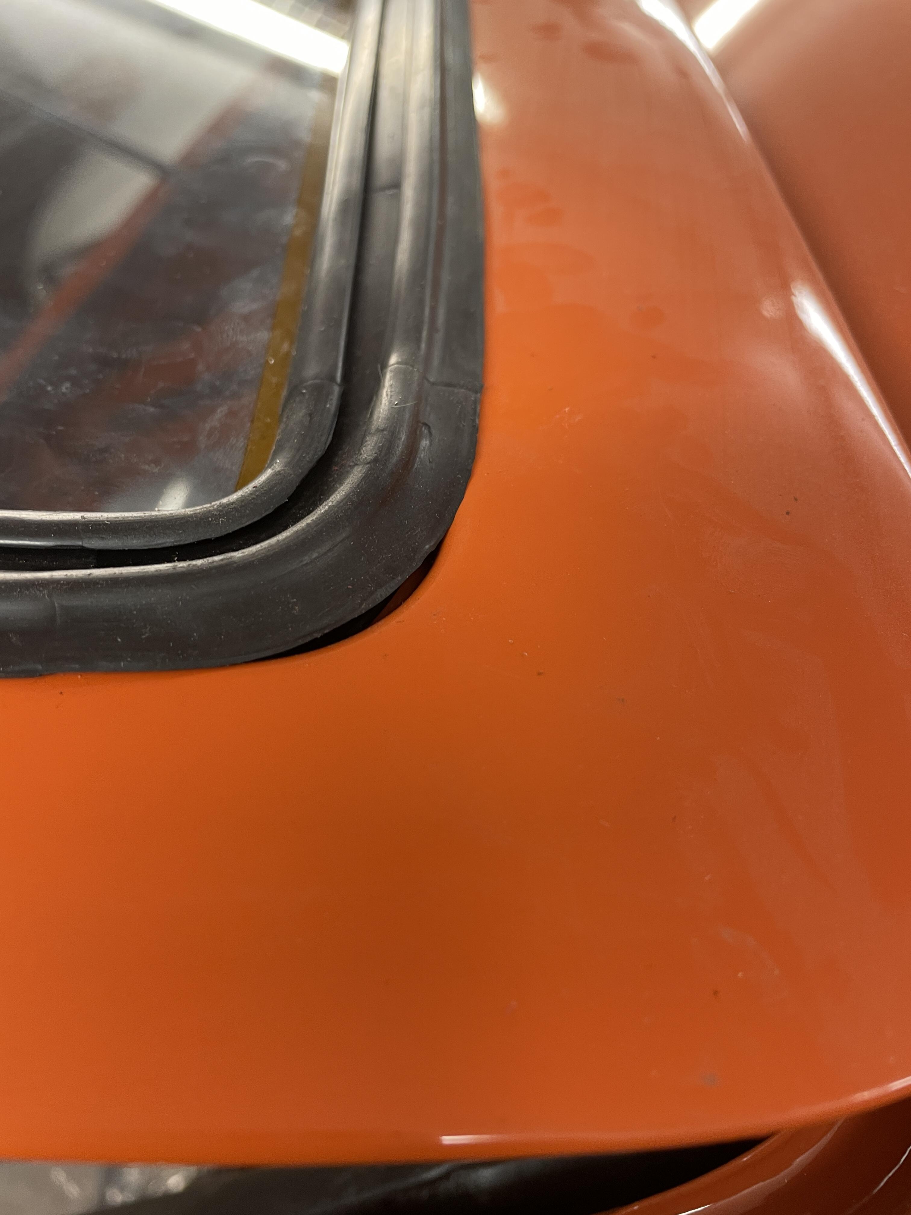
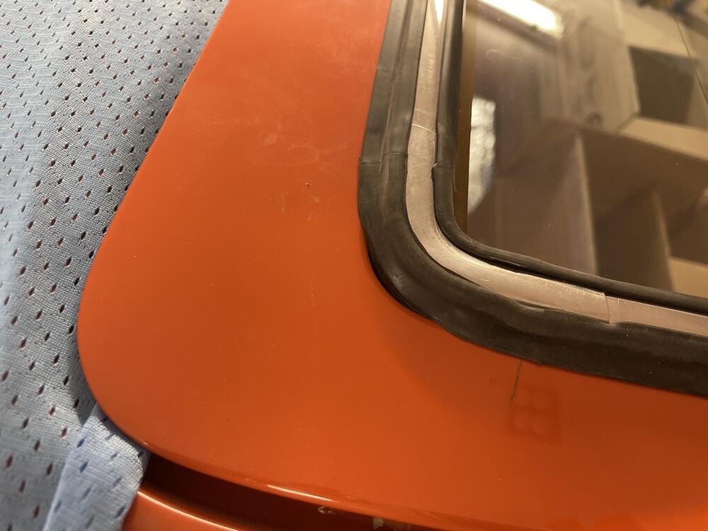
 It’s molded in the top corners for sure. The bottom ones have a curve but it’s not pronounced, so you could say they’re molded sort of. I don’t know how you would glue in the corners. It would require pressure keeping it against the hatch and the window should supply that. I guess you could glue it in without the window, fit the rest of the seal around the glass, and then complete the installation, but I am betting that would be REALLY tough to pull off. I think I’m going to have to leave this in for now and redo it later with a new seal. I need to get on to other things.
 -
Okay, I’ve pulled the window twice and am still having this problem with the top corners. Maybe this seal sucks. It has the right number that corresponds with the Precision seal, but it didn’t come in one of their green bags, so I’m not certain. It was part of a Z Car Depot kit and they aren’t great about fixing issues like this.
-
Good call on the metal trim. I didn’t realize it needed to go in before the window was installed because the several videos I watched of people doing this didn’t do that. I got the seal from Z Car Depot a while ago and threw out the bag with the house trays on Friday, so I don’t know which one it is. I pulled the window out this morning and have a tube of silicone lubricant coming in the mail tomorrow. I’ll put the metal trim on first and try again when I’m better prepared.
-
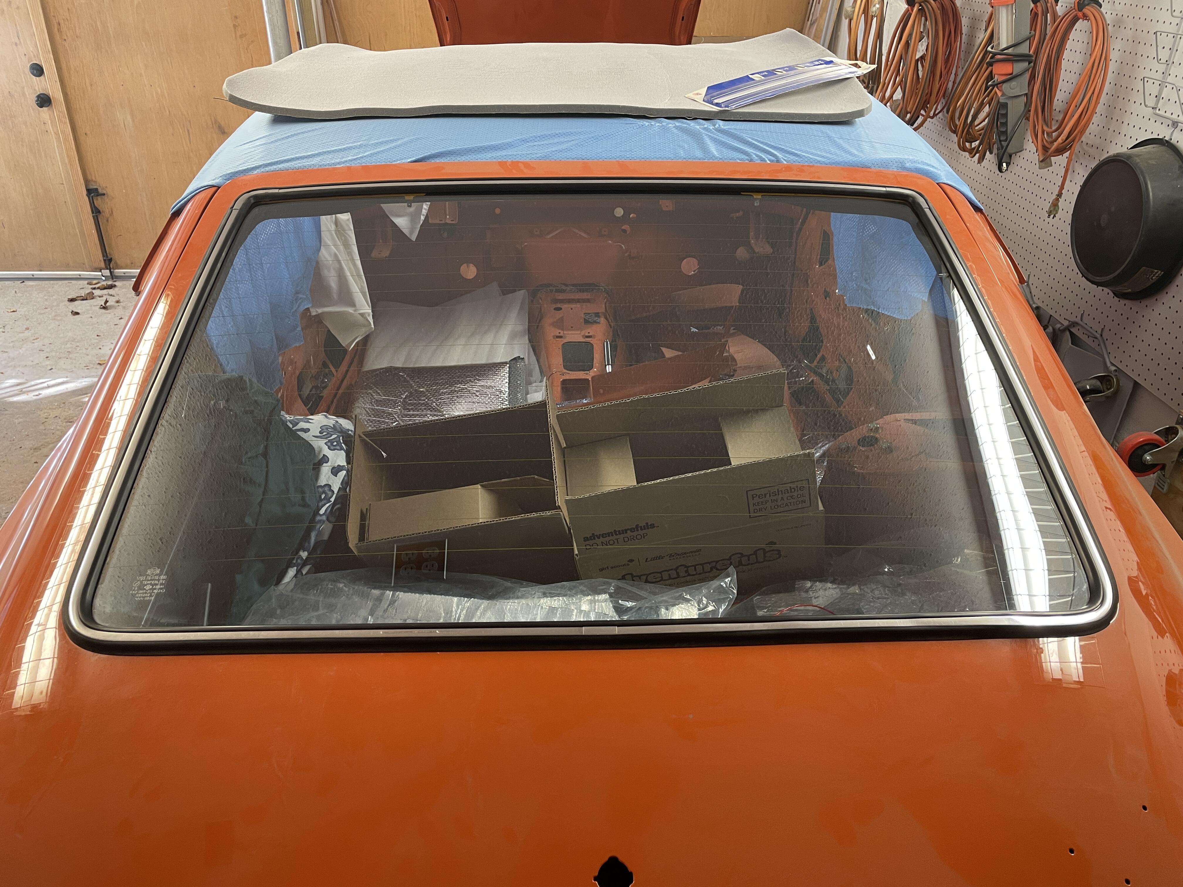
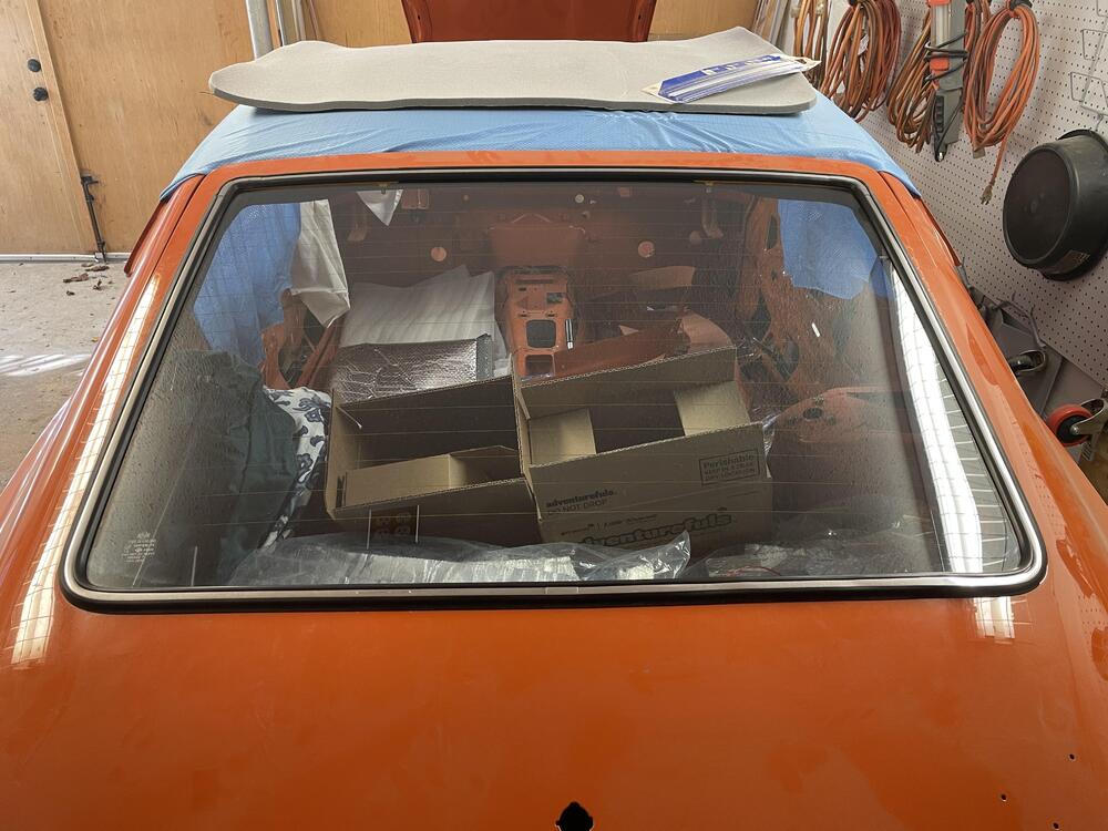
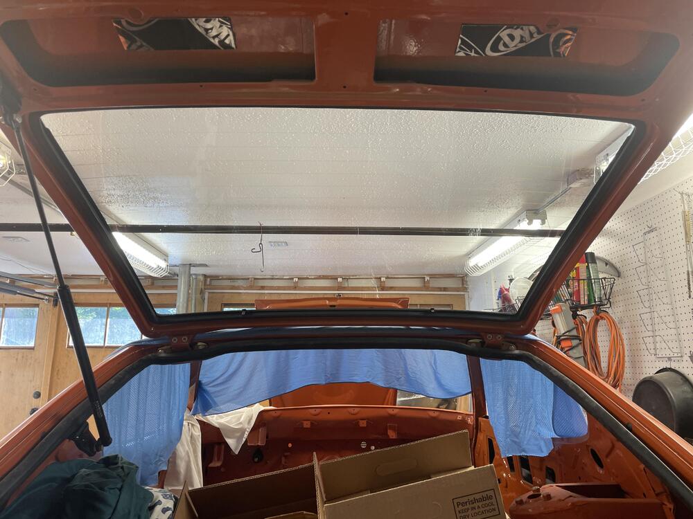
I installed my rear glass today and I have a problem. I can’t get the window to seat so that the two top corners are adequately covered by the weatherstripping. You can see above that there’s a sizable gap. This is the right side, which is the worse of the two. Am I stuck pulling the glass and doing this over again, or is there a trick I don’t know?

-
Oh, I didn’t know you had one. I assume you didn’t have any of the quality control issues or the problem with the cap? Have you discussed it in any of your threads?
-
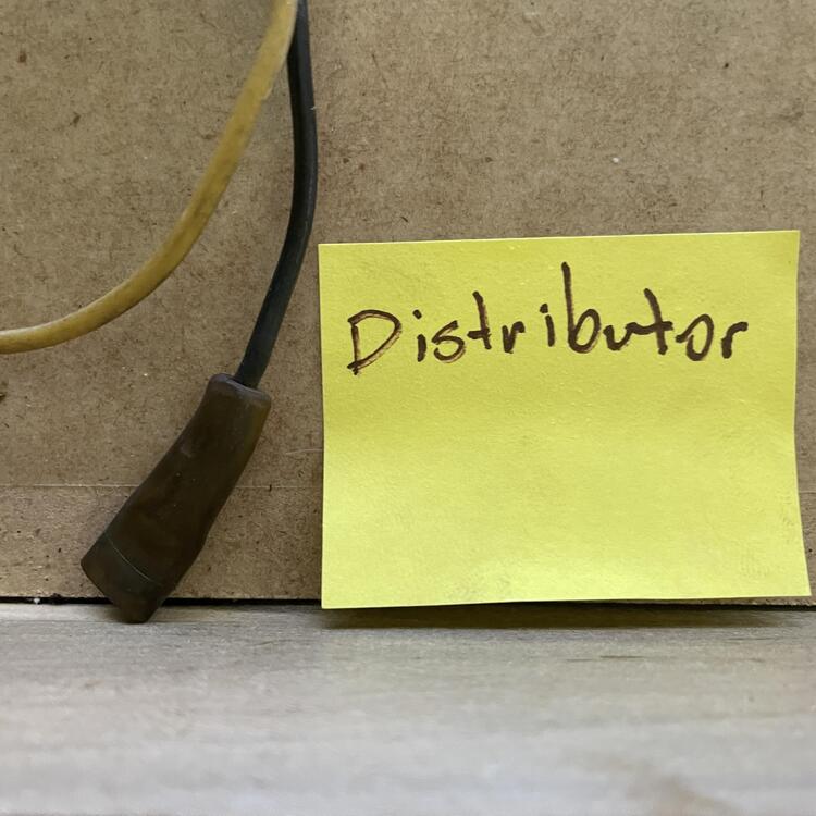
Got a slightly off topic question for you guys… I have a line on a rebuilt E12-80 280ZX distributor. I am wondering if this is the right move, or if I should be looking at something else. The something else list right now includes the 123 Distributor, the Pertronix setup, the Crane HI-6s, and the Electromotive XDI (potentially NLA). I like the idea of the 280ZX distributor because it is the simplest option listed above. However, I don't see reliable sources for replacement ignition modules and I hear they tend to burn out. I don't really want to put something with a computer in the car, but if I do I want the best performance I can get, which I think would be something like the XDI or the HI-6s. This is all on my mind because it lightly impacts the wiring choices I make. If the E12-80 is the best choice I should grab it while I can. Thoughts?
-
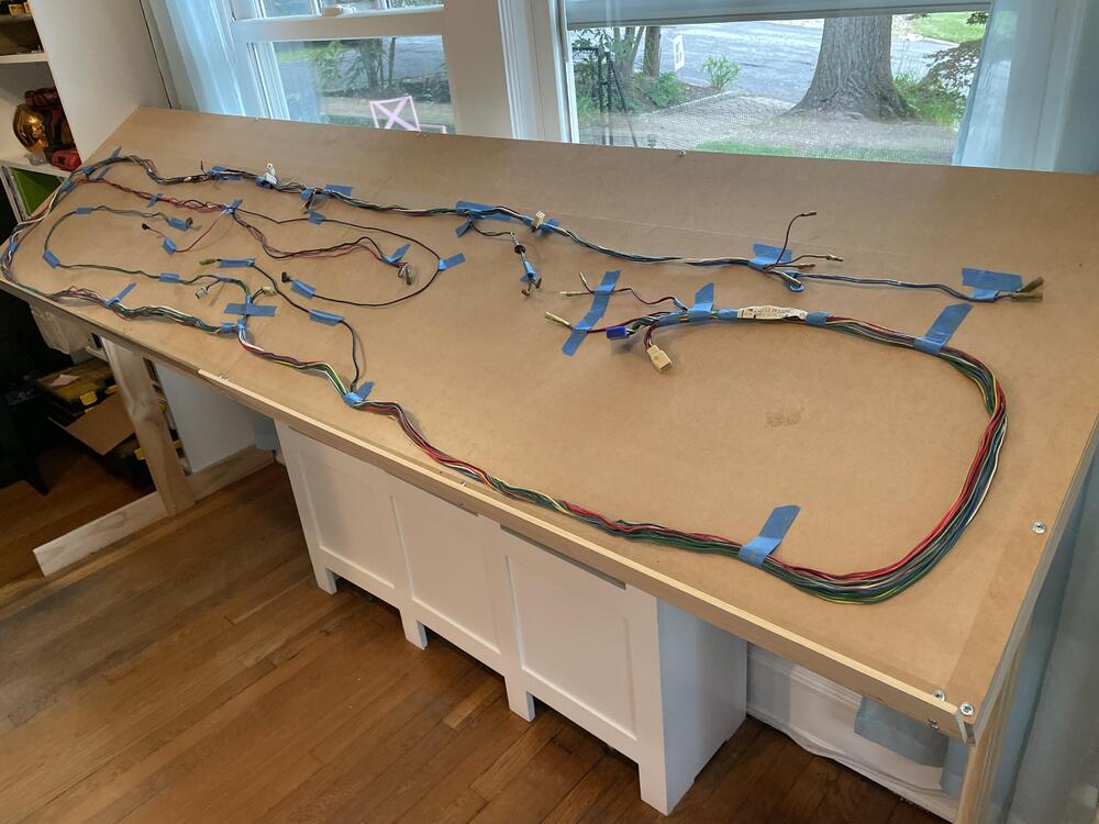
Thanks! I am hopeful that I didn't make any errors. If I did it would most likely be with the measurements of the wire lengths, since I was super tired of working on this harness by the time I got to that step. I checked them a couple of times, so they should be right, but there are a lot more splices in this harness than there were in the body harness and they are mostly blue or yellow, so difficult to keep straight. I'm also bothered by the fact that someone cut 4 of the wires and I can't tell you how long they should be or what the connector should be. :/ ––– Also, I was wondering if anyone knows what gauges the OEM wires are. It looks like there are 3, maybe 4 sizes, which I have tried to indicate with (heavy) and (thick) next to the wire colors in the table.
-
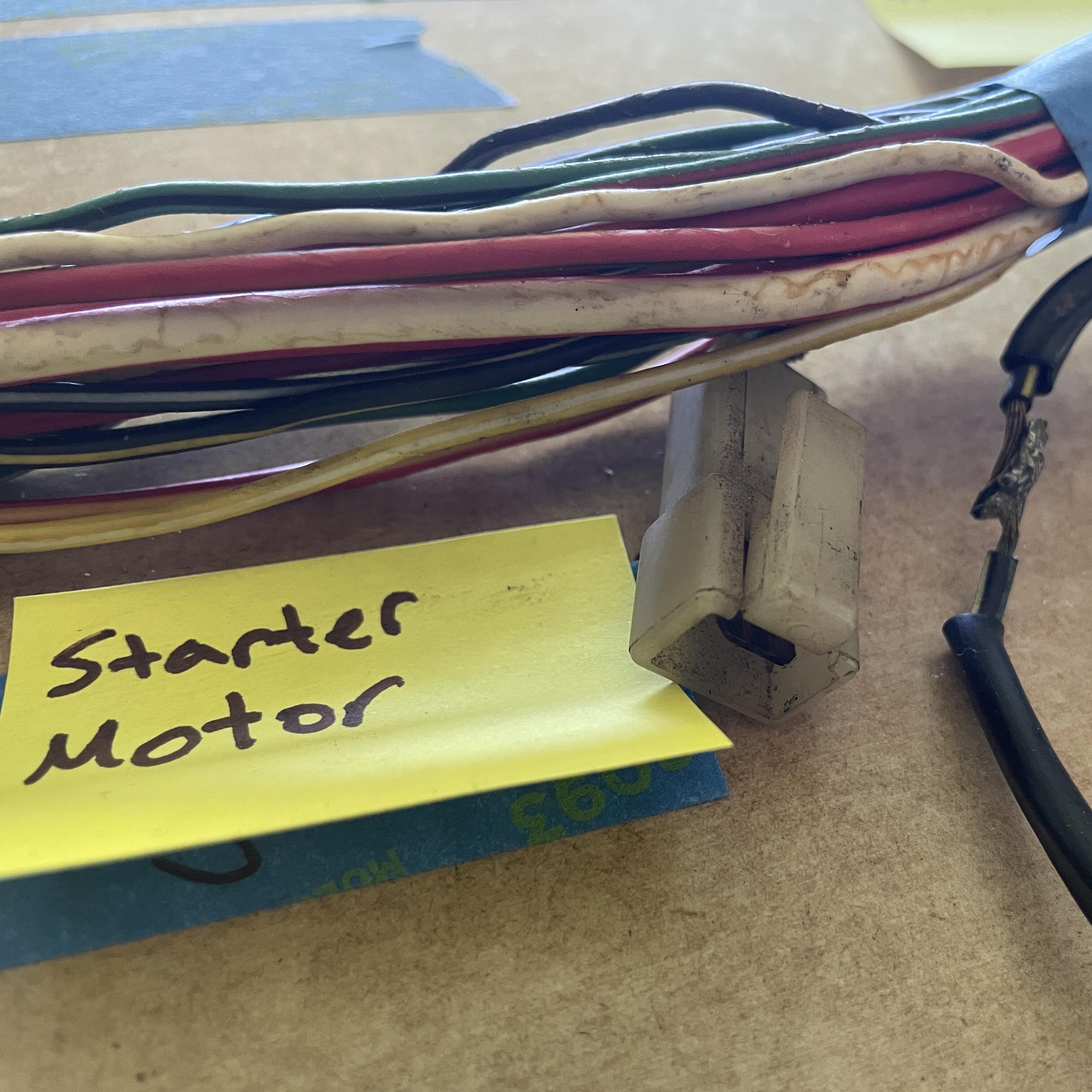
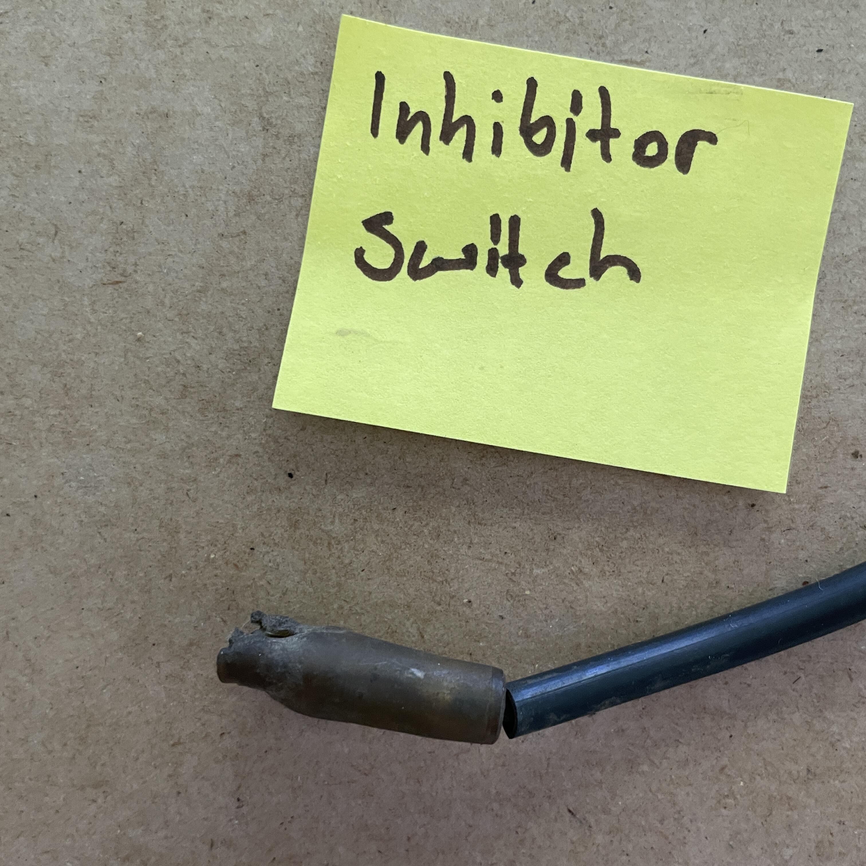
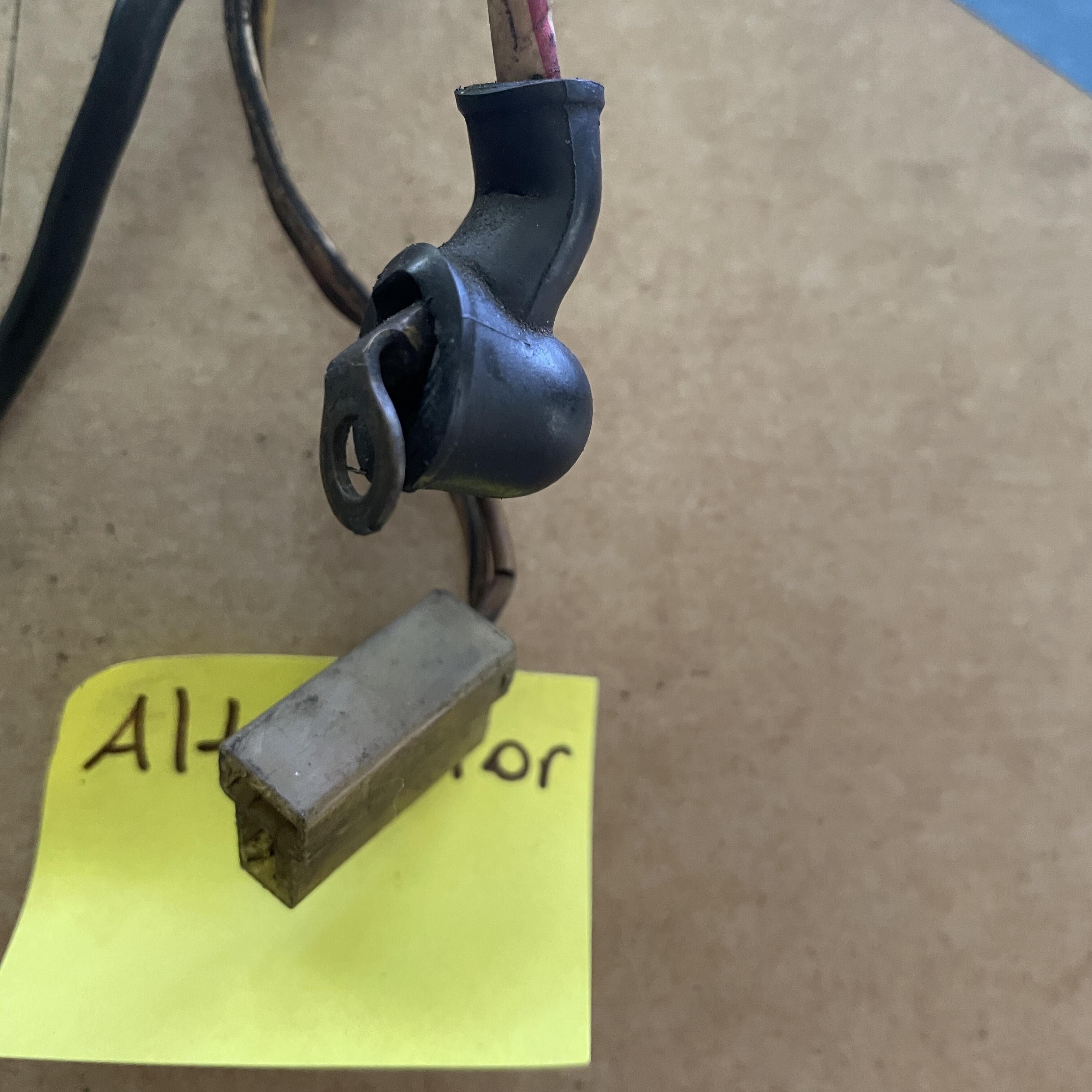
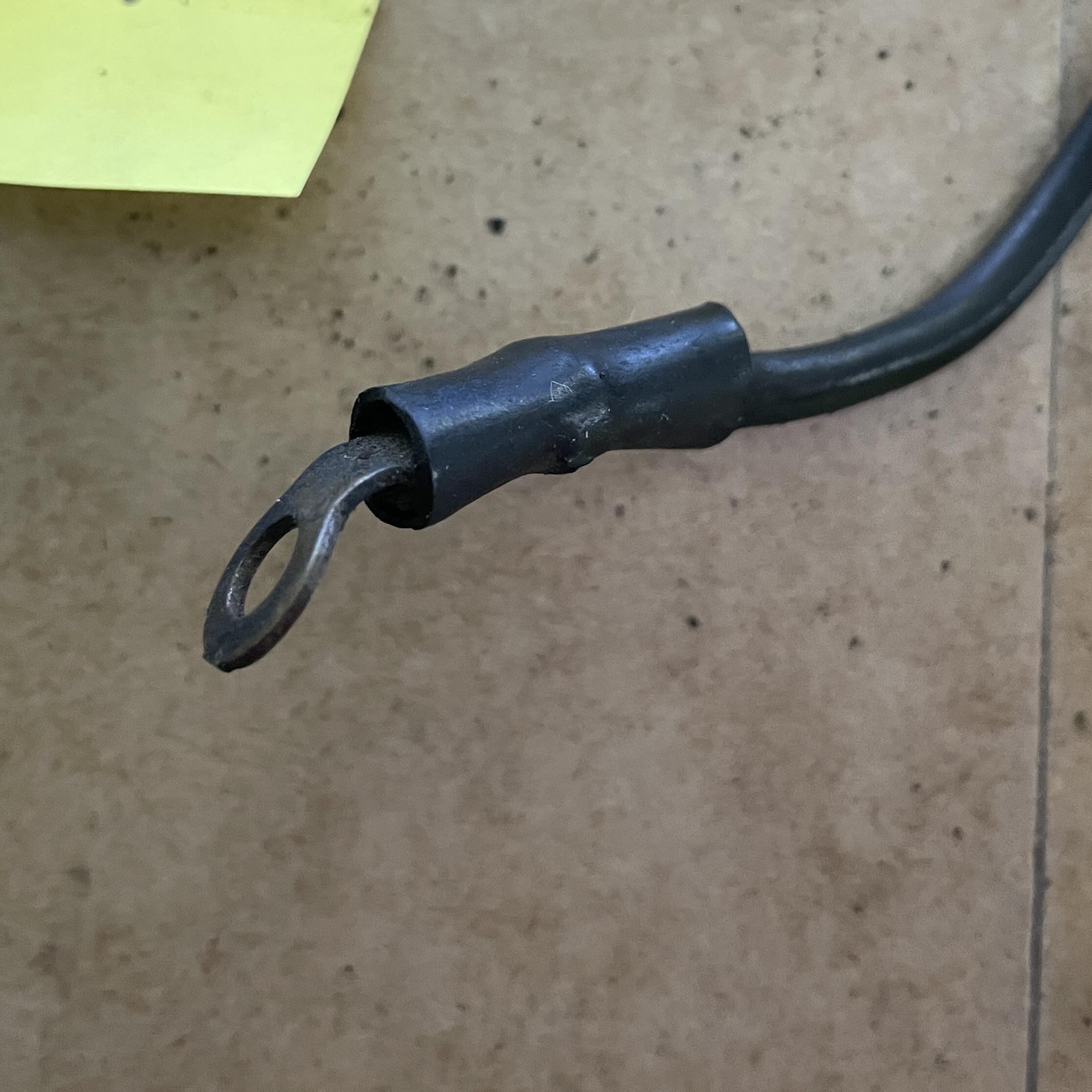
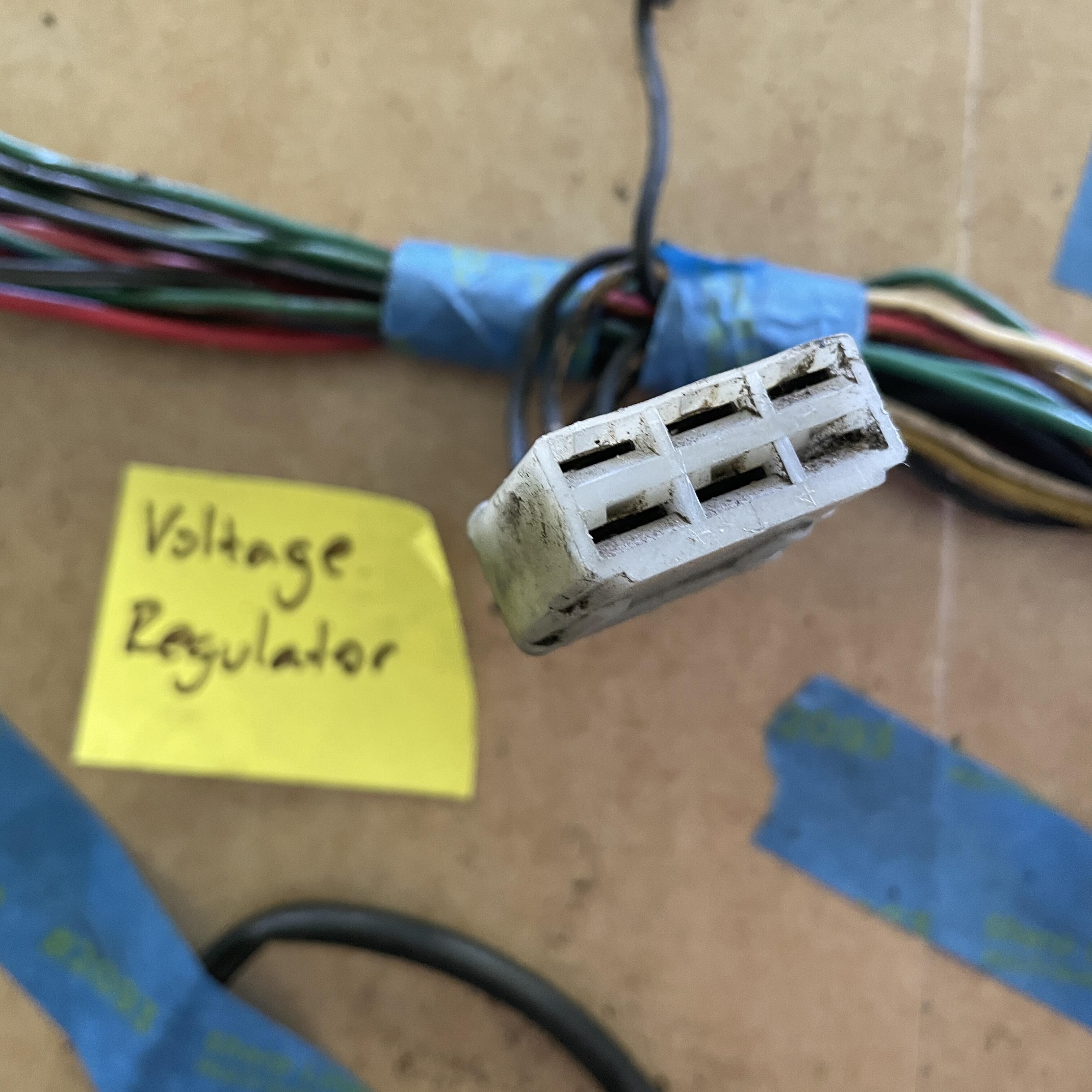
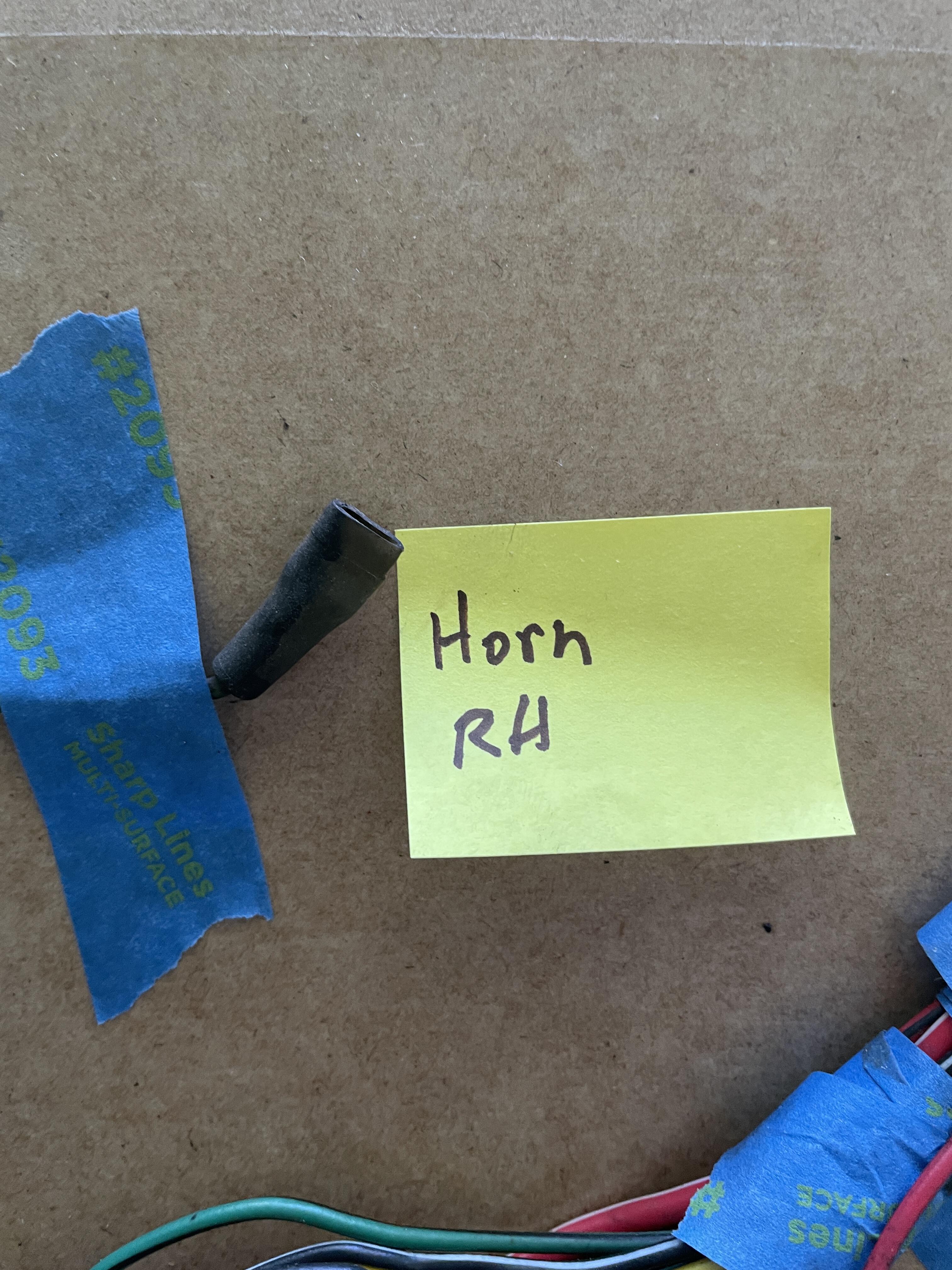
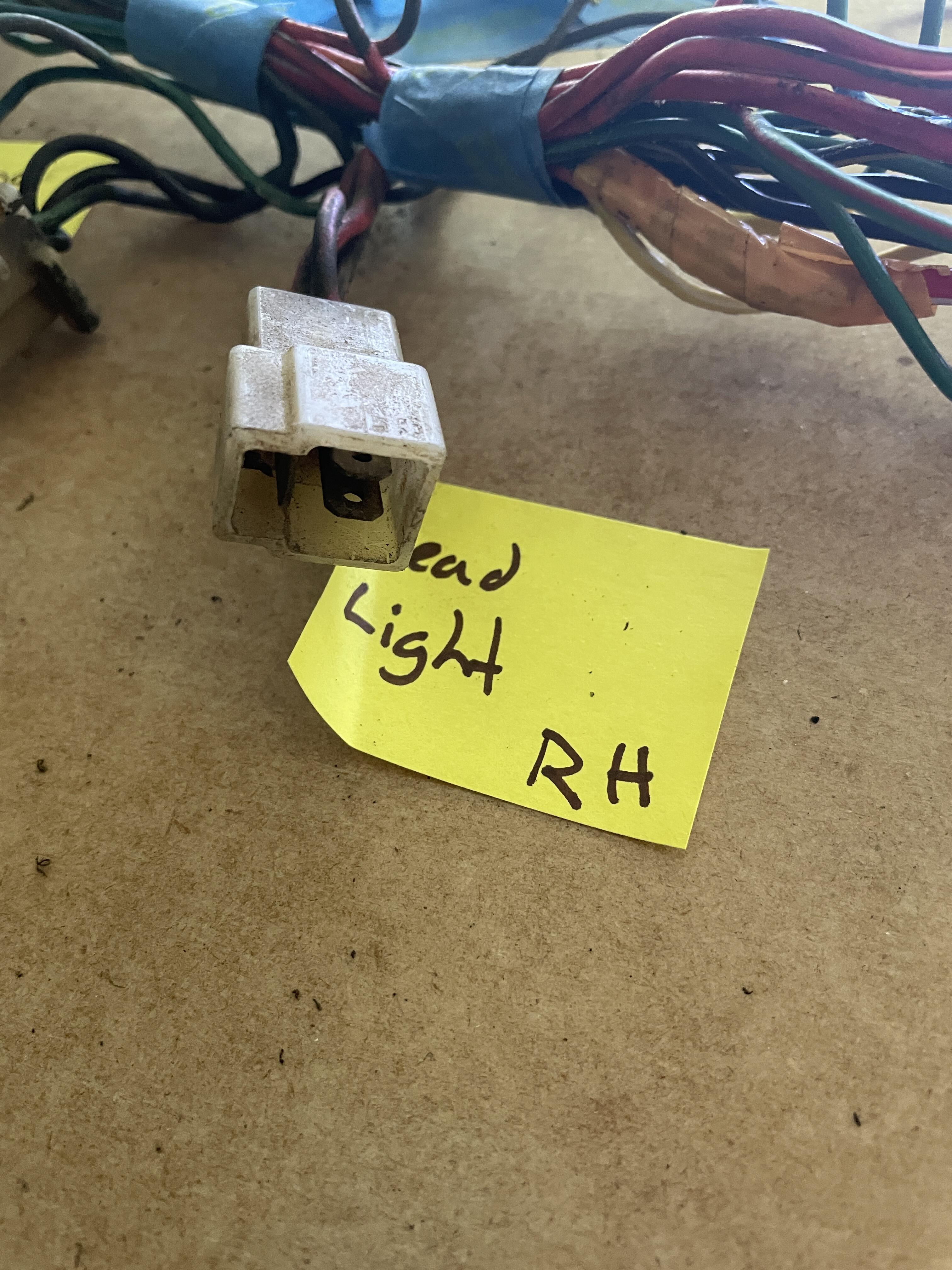
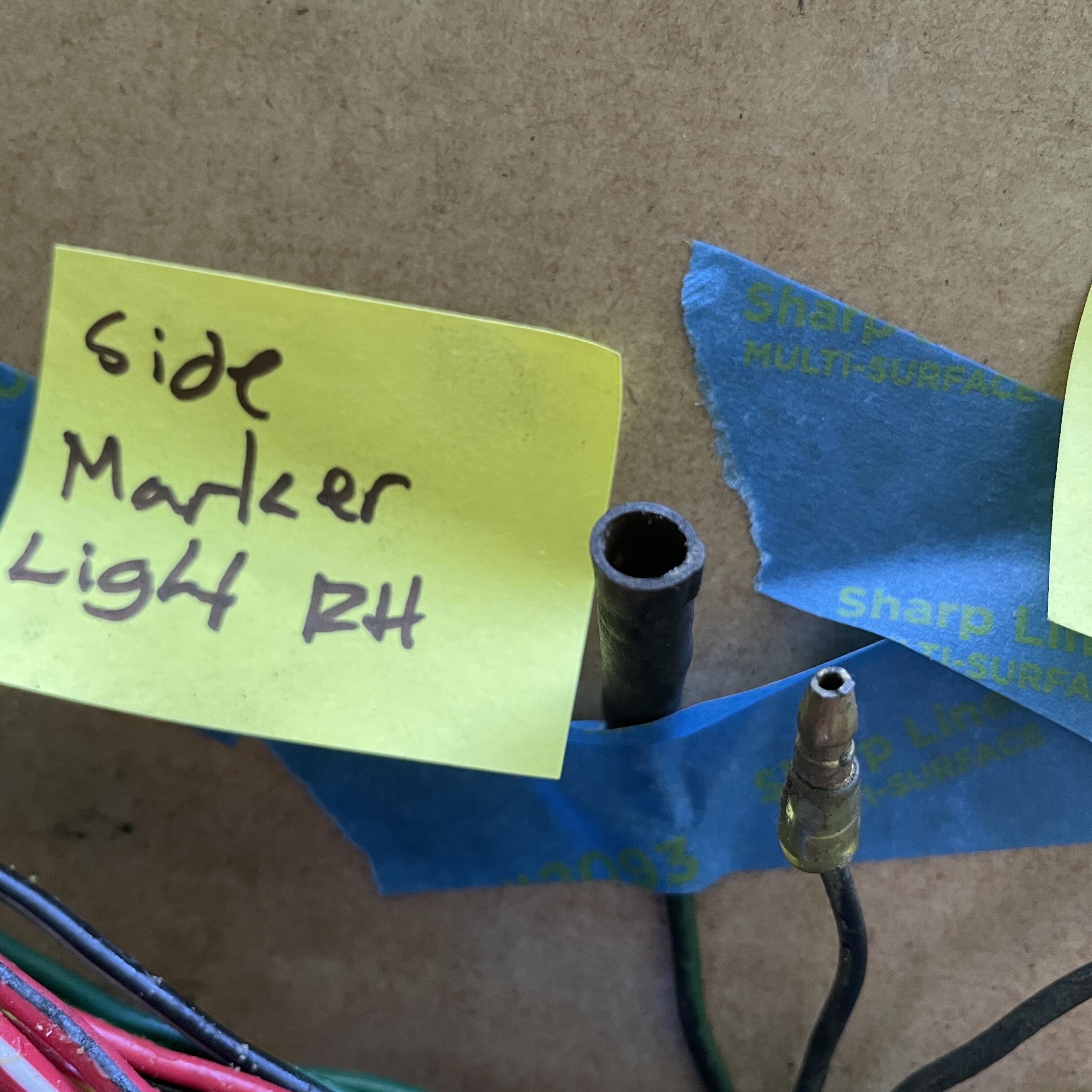
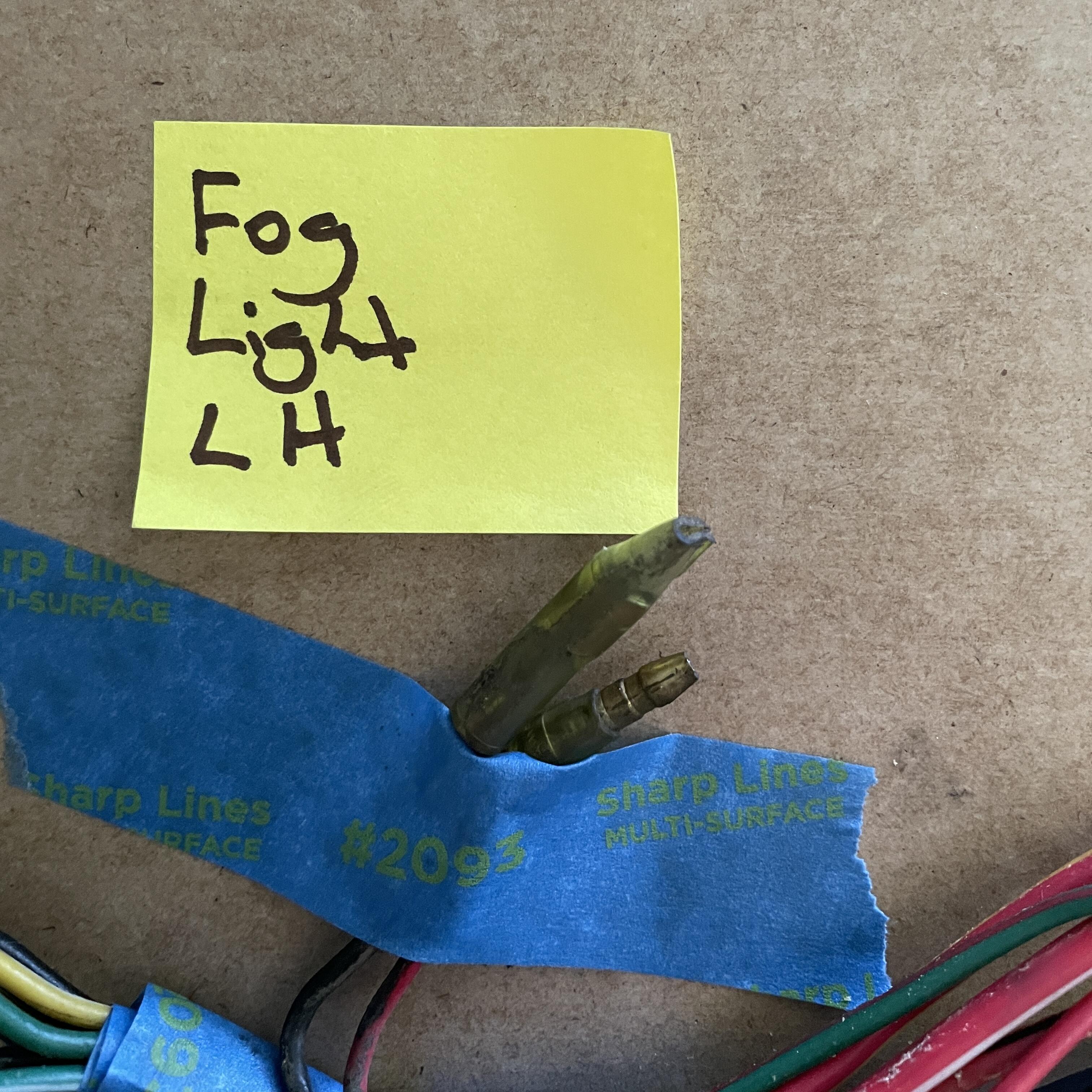
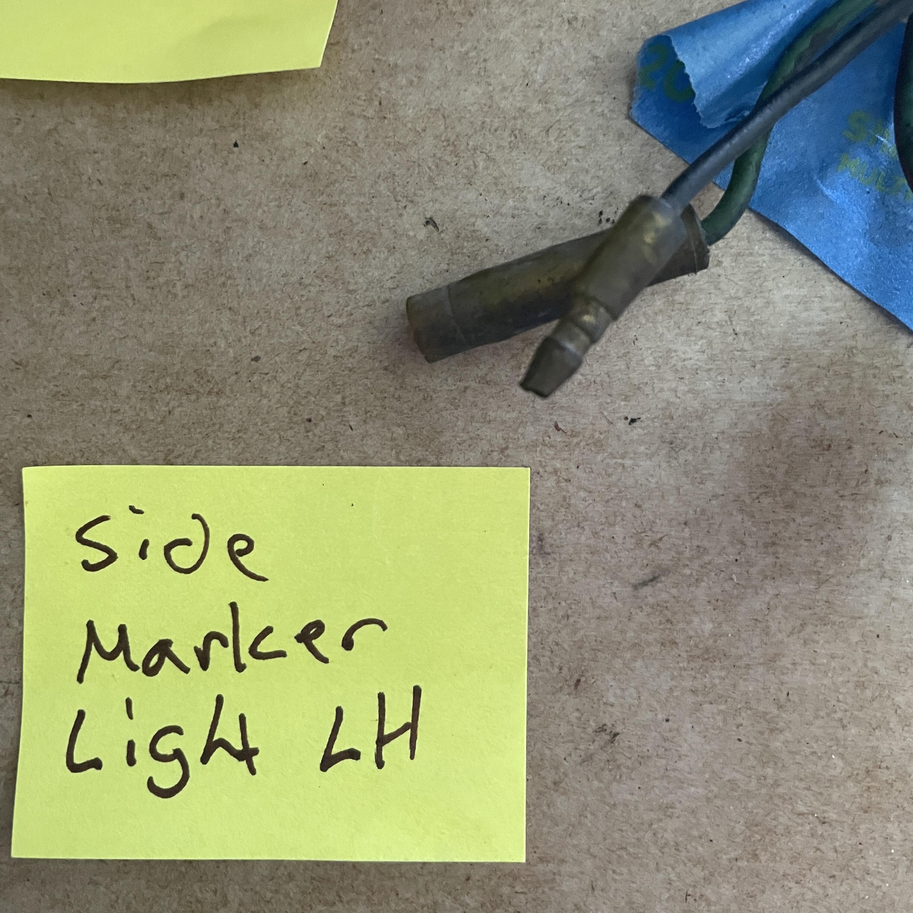
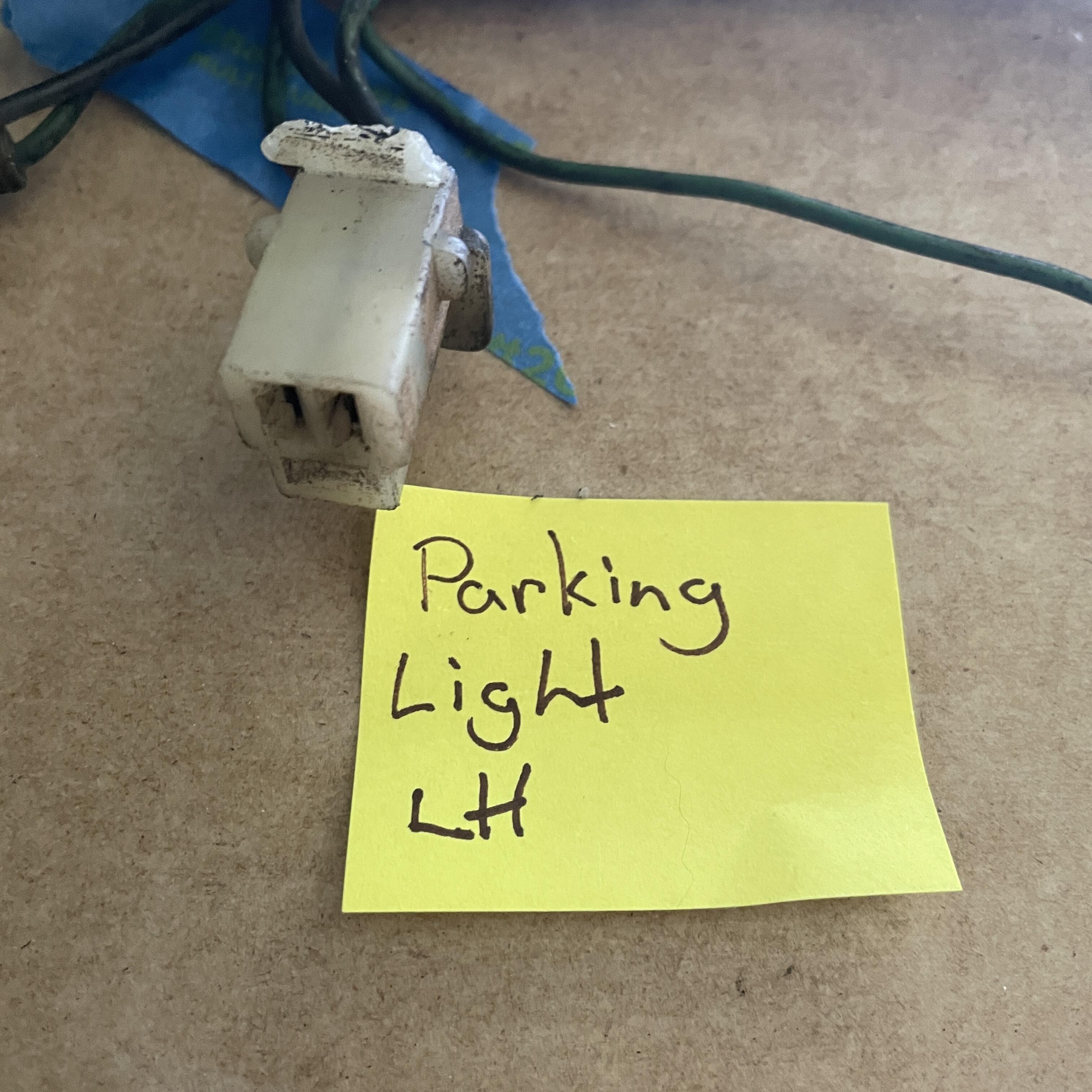
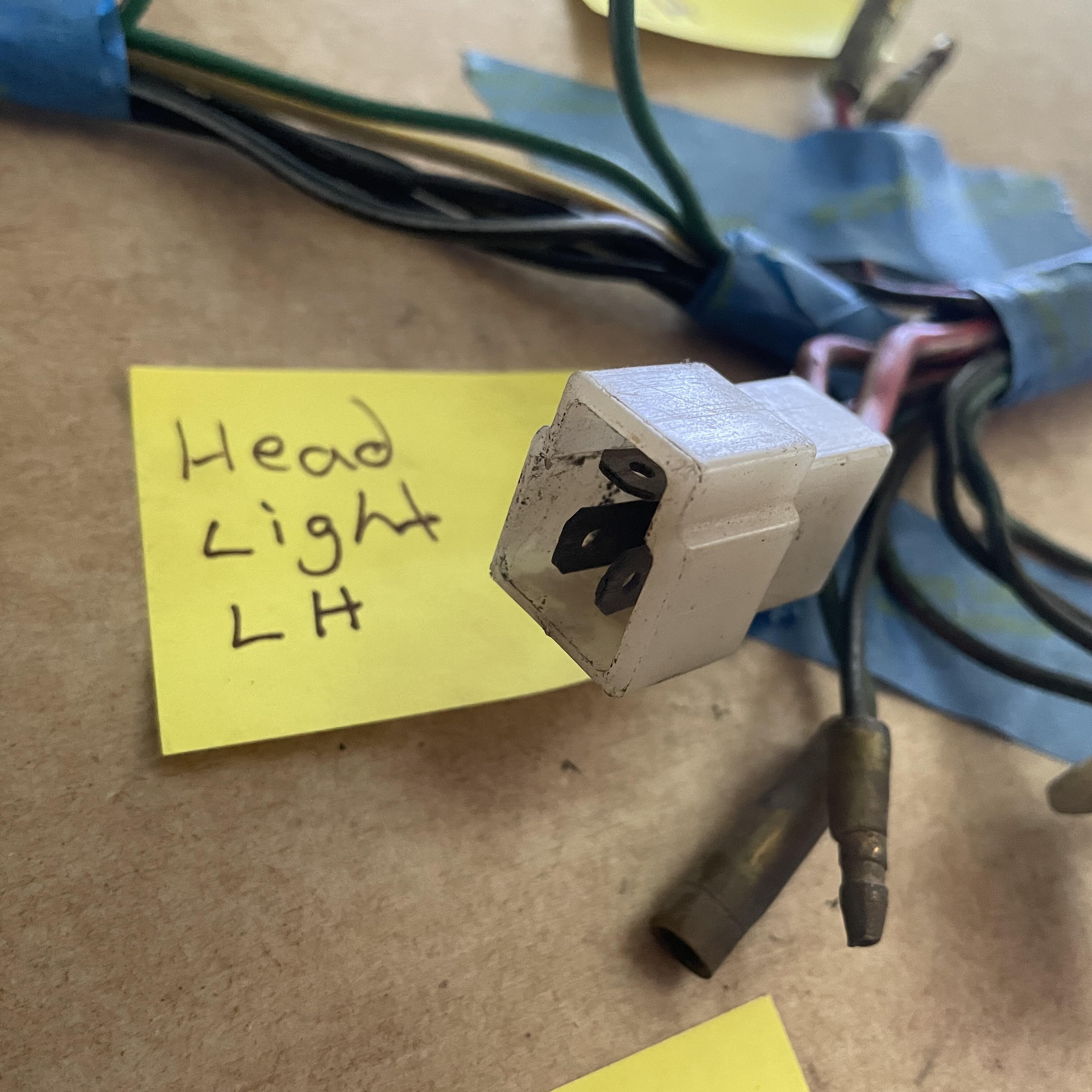
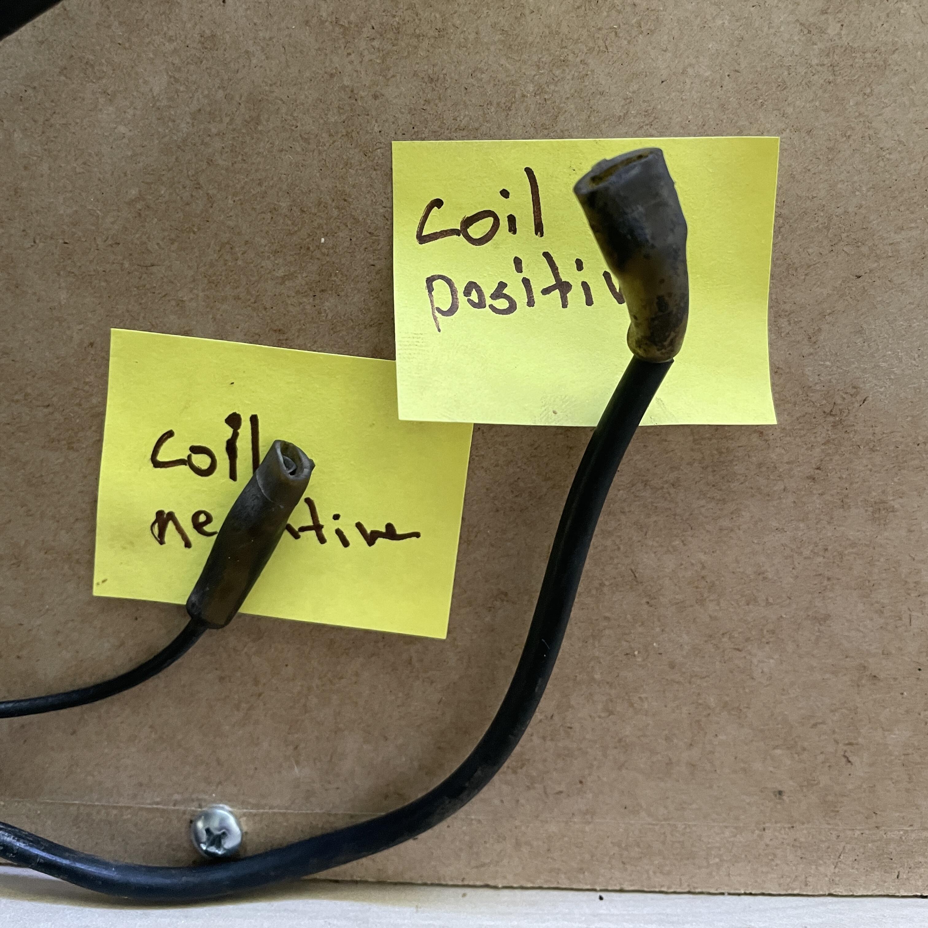
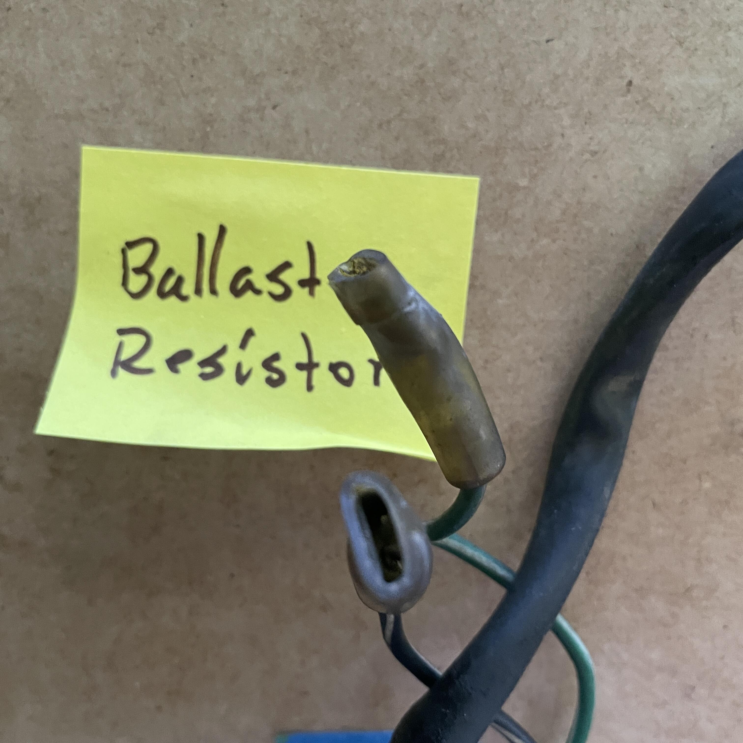
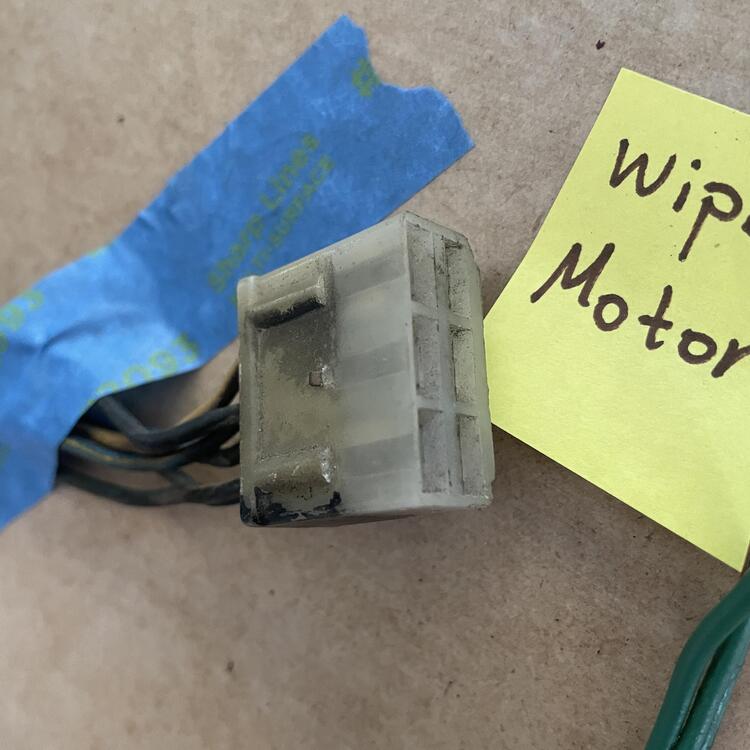
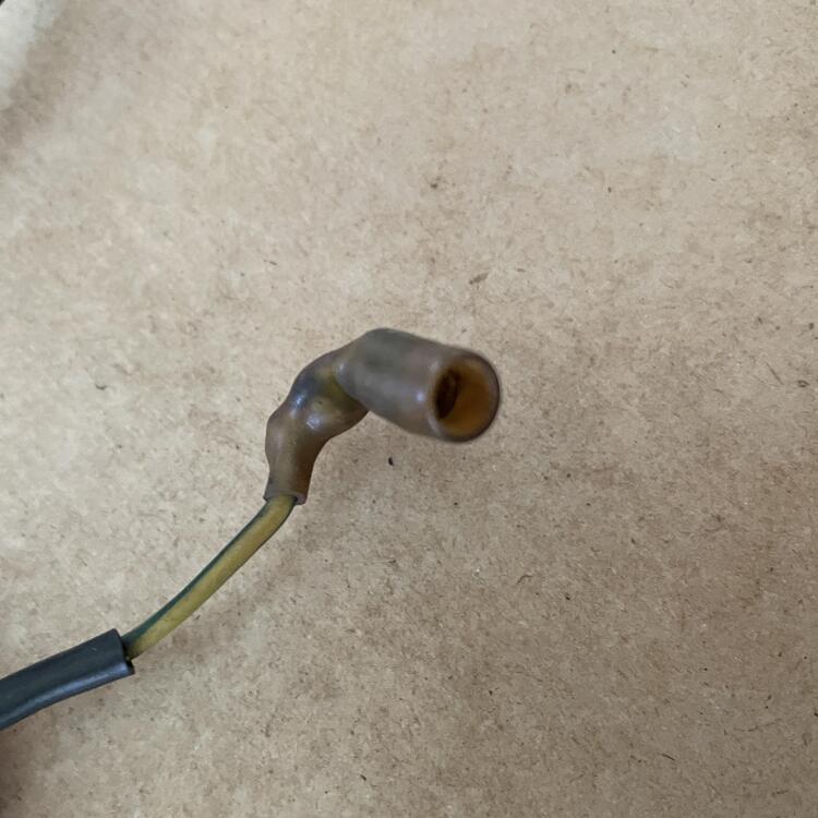
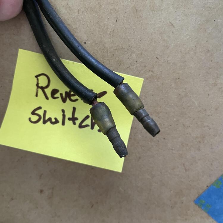
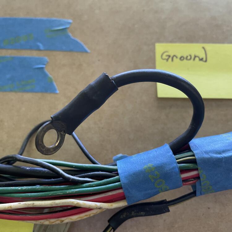
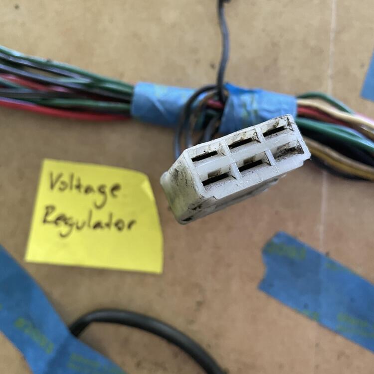
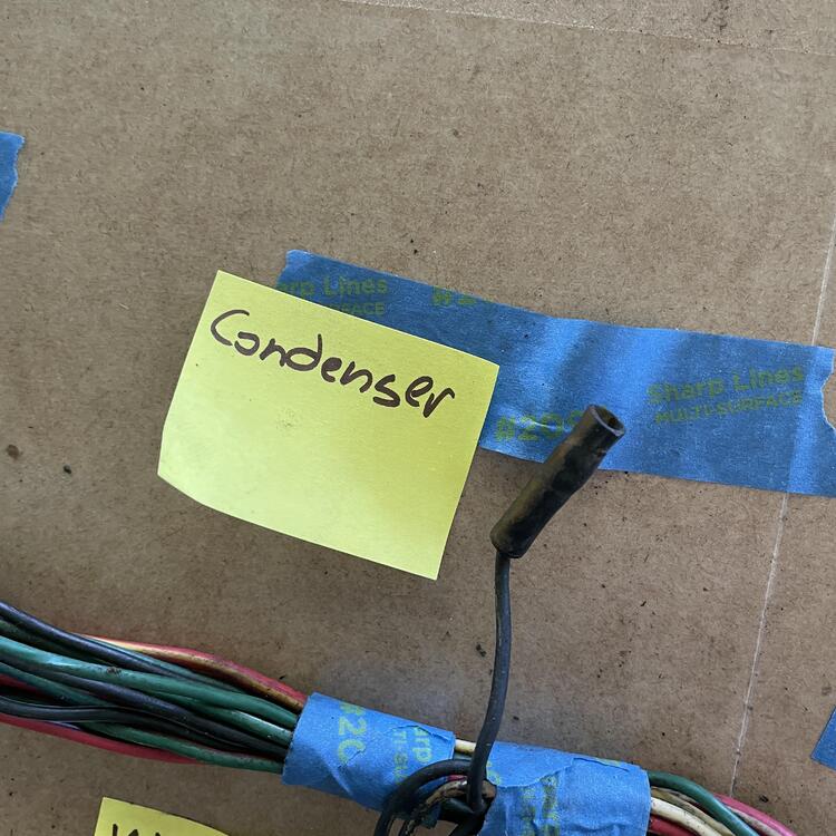
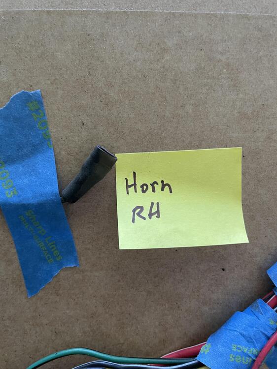
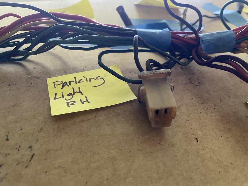
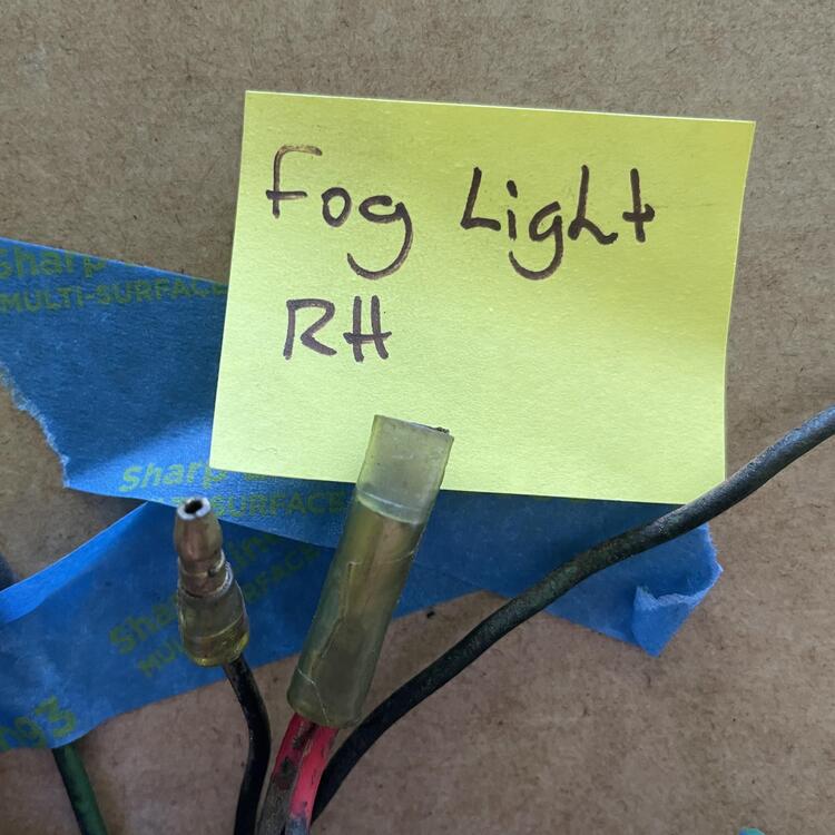
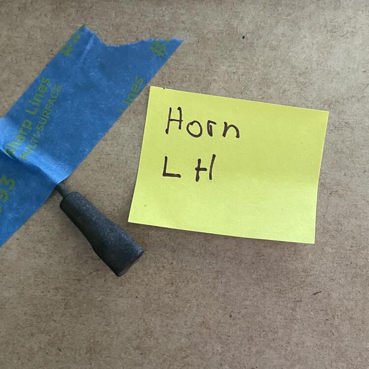
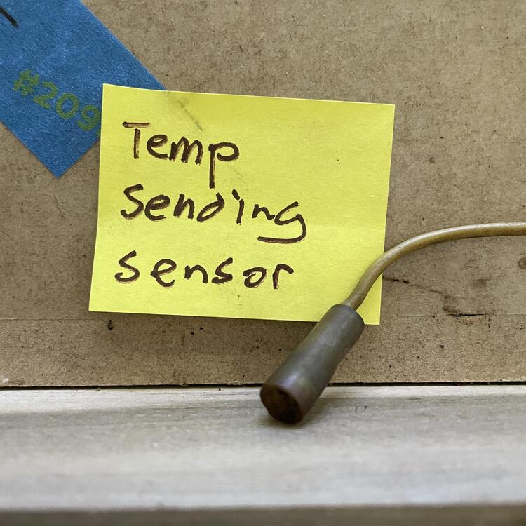
I have another table for you, this time for the engine harness in automatic cars. For manual cars, you would not have the Seatbelt Relay, the Inhibitor Switch, the Thermo Relay, or the Thermo Switch. In a 1973 car with a manual transmission, you WOULD have the Throttle Opener Vacuum Relay for the flat top carburetors (not included in the table). Note that there are a few things I was unsure of in here, so they are marked with a pink background in the table cell. The wires that were cut have indeterminant lengths, so I measured how long they were to the point where they were cut. Where the harness I have differs from the FSM and wiring diagrams, I have marked the change in red. The things I am most curious / worried about are the missing black w/ yellow wire that should be coming out of the blue 10-pin connector and the missing green w/ black wire that should be coming out of the green 10-pin connector. 1973 240z Engine Harness (Automatic Transmission) Inventory Position Component Connector Color Connector Style Connector Image Direction # of Pins # of Wires Diagram Wire Color Sample Wire Color Min. Feet of Wire Needed 1 Instrument Harness A Blue 10-Prong F 10 9 Red w/ Black Red w/ Black 6 (to Yellow Splice C) Red w/ White Red w/ White (Heavy) [See Headlight LH] Green w/ Black Green w/ Black [See Horn Relay] Green w/ Red Green w/ Red [See Horn Relay] – – – Yellow w/ Green Yellow w/ Green [See Low Brake Fluid/Pressure Sensor] Red w/ Black Red w/ Black [See Reverse Light Switch on Trans] Black w/ Yellow – ? Red Red [See Fog Light RH] Blue w/ Yellow Blue w/ White [See Wiper Motor] Instrument Harness B Green 10-Prong F 10 8 Black Black [See Ground - ?] Black Black (Heavy) 2 (to Blue Splice A) Green w/ Black – ? – – – – – – Green w/ Black Green w/ Black [See Parking & T/S & Side Front RH] Green w/ Red Green w/ Red [See Parking & T/S & Side Front LH] Blue Black w/ Yellow [See Seat Belt Relay] Green Green [See Seat Belt Relay] Green Green [See Seat Belt Relay] Instrument Harness C White Black 10-Prong F 10 8 Blue w/ Yellow Blue w/ Yellow [See Wiper Motor] Red Red (Thick) [See Headlight RH] Green w/ Blue Green w/ Blue 5 (to Blue Splice F) Red w/ Blue Red w/ Blue [See Inspection Light] Red w/ Yellow Red w/ Yellow (Thick) [See Headlight LH] – – – – – – Black Black [See Water Tank] Blue Blue [See Wiper Motor] Yellow w/ Green Yellow w/ Green [See Intermittent Relay] Instrument Harness D Black White 10-Prong F 10 9 Blue w/ Red Blue w/ Red 2 (to Yellow Splice A) Yellow w/ Black Yellow w/ Black [See Oil Pressure Switch] Black w/ White Black w/ White 2 (to Orange Splice A) Black w/ White Black w/ White 4 (to Blue Splice C) Yellow w/ White Yellow w/ White [See Temperature Sending Sensor] – – – Green Green [See Hazard] White White [See Hazard] Black w/ White Black [See Ballast Resistor] Green w/ White Green w/ White [See Ballast Resistor] Instrument Harness E White 1 1 White w/ Red White w/ Red (Heavy) [See Alternator] Instrument Harness F White 1 1 White White (Heavy) 3 (to Green Splice A) Horn Relay Clear Spade F 1 1 Green w/ Black Green w/ Black 2 Clear Spade F 1 1 Green Green 7 (to Yellow Splice D) Clear Spade F 1 1 Green w/ Red Green w/ Red 2 Intermittent Relay White 4-Prong F 4 3 Yellow Yellow [See Wiper Motor] Green Black 4 (to Blue Splice B) Yellow w/ Green Yellow w/ Green 2 Hazard White 2-Prong (90 Degree) F 2 2 White White 2 Green Green 2 Yellow Splice A N/A N/A N/A N/A 2 2 Blue w/ Red N/A Red w/ Black 2 Seatbelt Relay (A/T) White 4-Prong F 6 6 Black w/ Yellow Black w/ Yellow [See Neutral Safety Switch] Black w/ Yellow Black w/ Yellow 6 (to Yellow Splice C) Black w/ Yellow Black w/ Yellow [See Inhibitor Switch] Black Black 1 (to Blue Splice A) Green Green 3 Green Green 3 Wiper Motor White 6-Prong F 6 5 Blue w/ White Blue w/ White 4 Blue Blue 4 Blue w/ Yellow Blue w/ Yellow 4 Yellow Yellow 4 Black Black 2 (to Blue Splice A) Blue w/ Red Blue w/ Red 2 (from Yellow Splice A) Ground - ? Missing 1 1 Black 4+ (from Blue Splice A) Water Tank Clear Spade F 1 1 Black w/ Yellow Black w/ Yellow 8 Black Spade M 1 1 Black Black 8 Low Brake Fluid/Pressure Sensor Clear Bullet (Large) F 1 1 Yellow w/ Green Yellow w/ Green 9 Yellow Splice B N/A N/A N/A N/A 2 2 Black w/ Yellow N/A Black w/ Yellow Orange Splice A N/A N/A N/A N/A 2 2 Black w/ White N/A Black w/ Yellow Blue Splice A N/A N/A N/A N/A 3 3 Black N/A Black Black (Heavy) 2 (to Blue Splice B) 3 Reverse Light Switch on Trans Clear Bullet M 1 1 Red w/ Black Red w/ Black 4 Clear Bullet M 1 1 Red Red w/ Black 3 (from Yellow Splice A) Neutral Safety Switch (for solenoid power) Clear Bullet F 1 1 Black w/ Yellow Black w/ Yellow 5 Clear Bullet F 1 1 Black w/ Yellow Black w/ Yellow 5 Blue Splice B N/A N/A N/A N/A 3 3 Black N/A Black (Heavy) Black (Heavy) 2 (to Blue Splice C) Blue Splice C N/A N/A N/A N/A 3 3 Black w/ White N/A Black w/ White Green Green Splice A N/A N/A N/A N/A 2 2 White (Heavy) N/A White 4 Starter Motor White 1-Prong M 1 1 White White (Heavy) 1 (from Green Splice A) Starter Ground Black Ring N/A 1 1 Black Black (Heavy) 2 (from Blue Splice B) Inhibitor Switch (A/T) Clear Spade F 1 1 Black w/ Yellow Black w/ Yellow 4 Blue Splice D N/A N/A N/A N/A 3 3 Black N/A Black (Heavy) Black (Heavy) 6 Oil Pressure Switch 1 Yellow w/ Black Yellow w/ Black 6 Alternator White 2-Prong F 2 2 White w/ Black White w/ Black 5 Yellow Yellow [See Voltage Regulator] Black Ring w/ Cap N/A 1 1 White w/ Red White w/ Red (Heavy) 5 Alternator Ground Black Ring N/A 1 1 Black Black (Heavy) 2 (from Blue Splice B) 7 Voltage Regulator White 6-Prong F 6 5 Yellow Yellow 2 White White 5 Black Black 5 White w/ Black White w/ Black 5 Black w/ White Black w/ White 5 Distributor Condenser Clear Bullet F 1 1 Black w/ White Black w/ White 5 5 Inspection Light Clear Bullet F 1 1 Red w/ Blue Red w/ Blue 7 Blue Splice E N/A N/A N/A N/A 2 2 Black N/A Black 2 (from Blue Splice D) Yellow Splice C N/A N/A N/A N/A 2 2 Red w/ Black N/A Red w/ Black Blue Splice F N/A N/A N/A N/A 2 2 Green w/ Blue N/A Green w/ Blue Yellow Splice D N/A N/A N/A N/A 2 2 Green N/A Green Orange Splice B N/A N/A N/A N/A 2 2 Red w/ White (Heavy N/A Red w/ Black (Thick) 8 Side Marker Lamp RH Clear Bullet F 1 1 Green w/ Blue Green w/ Blue 2 (from Blue Splice F) Clear Bullet M 1 1 Black Black 2 (from Blue Splice E) Parking & T/S & Side Front RH White 3-Prong F 3 5 Black Black 6 Black 6 Green w/ Blue Green w/ Blue 2 (from Blue Splice F) Green w/ Blue 2 (to Blue Splice G) Green w/ Black Green w/ Black 6 Head Light RH White 3-Prong M 3 3 Red Red (Thick) 6 Red w/ Black Red w/ Black 6 Red w/ White Red w/ Black 1 (from Yellow Splice C) Fog Light RH Clear Bullet M 1 1 Black Black 6 Clear Bullet F 1 2 Red Red [See Fog Light LH] 6 Horn RH Clear Spade F 1 1 Green Green 6 Blue Splice G N/A N/A N/A N/A 2 2 Green w/ Blue N/A Green w/ Blue Blue Splice H N/A N/A N/A N/A 2 2 Black N/A Black 9 Horn LH Clear Spade F 1 1 Green Green 8 Fog Light LH Clear Bullet M 1 1 Black Black 8 Clear Bullet F 1 1 Red Red 8 Parking & T/S & Side Front LH White 3-Prong F 3 3 Black Black 8 Green w/ Red Green w/ Red 8 Green w/ Blue Green w/ Blue 1 (from Blue Splice G) Head Light LH White 3-Prong M 3 3 Red w/ Yellow Red w/ Yellow 8 Red w/ White Red w/ White (Heavy) 8 Red w/ Black Red w/ Black 3 (to Yellow Splice C) Side Marker Lamp LH Clear Bullet F 1 1 Black Black 8 Clear Bullet M 1 1 Green w/ Blue Green w/ Blue 1 (from Blue Splice G) 10 Thermo Switch (A/T) - ? Missing 1 Black w/ Yellow 7+ (from Yellow Splice B) Thermo Relay (A/T) Missing 1 Black Black 9+ Missing 1 Green Green 9+ 11 Temperature Sending Sensor Clear Bullet F 1 1 Yellow w/ White Yellow w/ White 13 Distributor Clear Spade F 1 1 Black Black [See Coil] Coil Positive Clear Spade F 1 1 Black w/ White (w/ Shroud) Black w/ White (w/ Shroud) 12 (from Orange Splice A) Coil Negative Clear Spade F 1 1 Black Black 2 Balast Resistor Clear Spade F 1 1 Green w/ White Green w/ White 12 Clear Spade F 1 1 Black w/ White Black w/ White 12


-
Question for the room: I’ve seen that the recommended sequence for assembling the interior of the car starts with the grommets in the firewall and then the rest of the firewall parts, but I imagine getting the tubes, wires, and other stuff that goes through those grommets is easier with them out, and I won’t be ready to put those thing in for a while. Is there a trick for doing this with the grommets installed and all of the insulation, boards, and stuff (not counting the dashboard) bolted to the firewall already? My interior was in cardboard boxes when I bought the car and I didn’t get a chance to take notes on the disassembly sequence, so this is a knot I have to unravel.
-
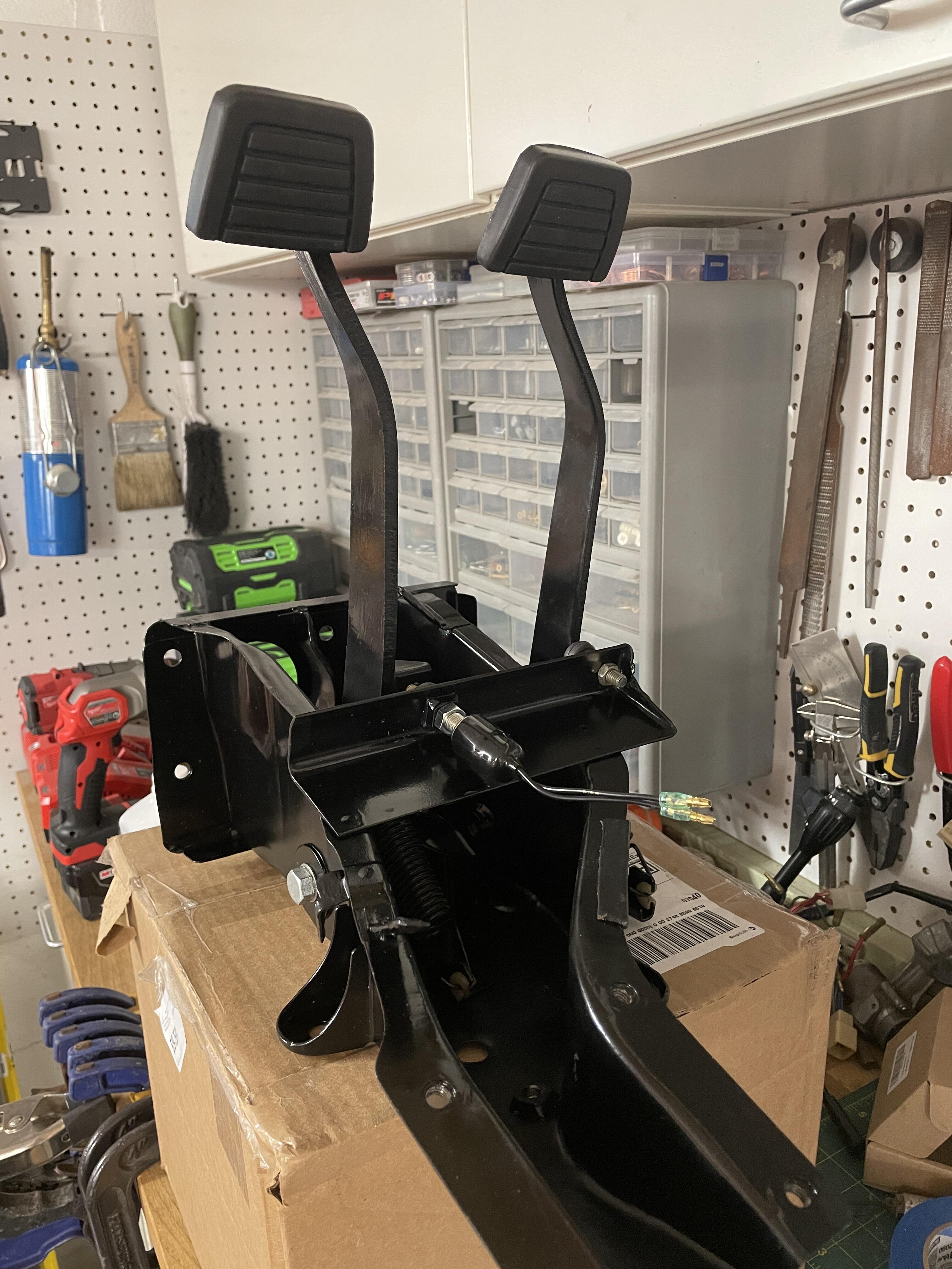
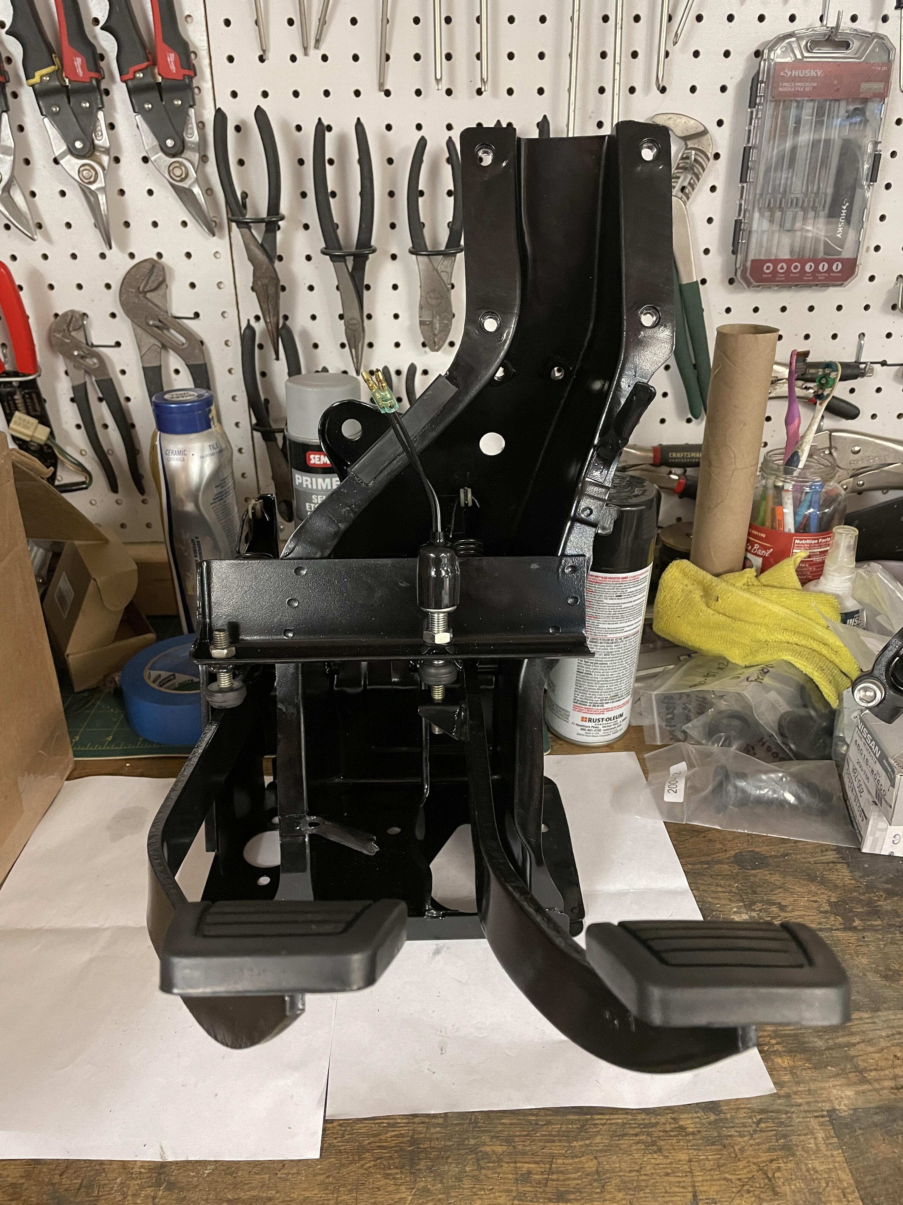
I just opted for a glob of lithium grease between the pedal tube and the inner tube, as well as between the inner tube and the bolt. Keeping it off the threads was fun!
-
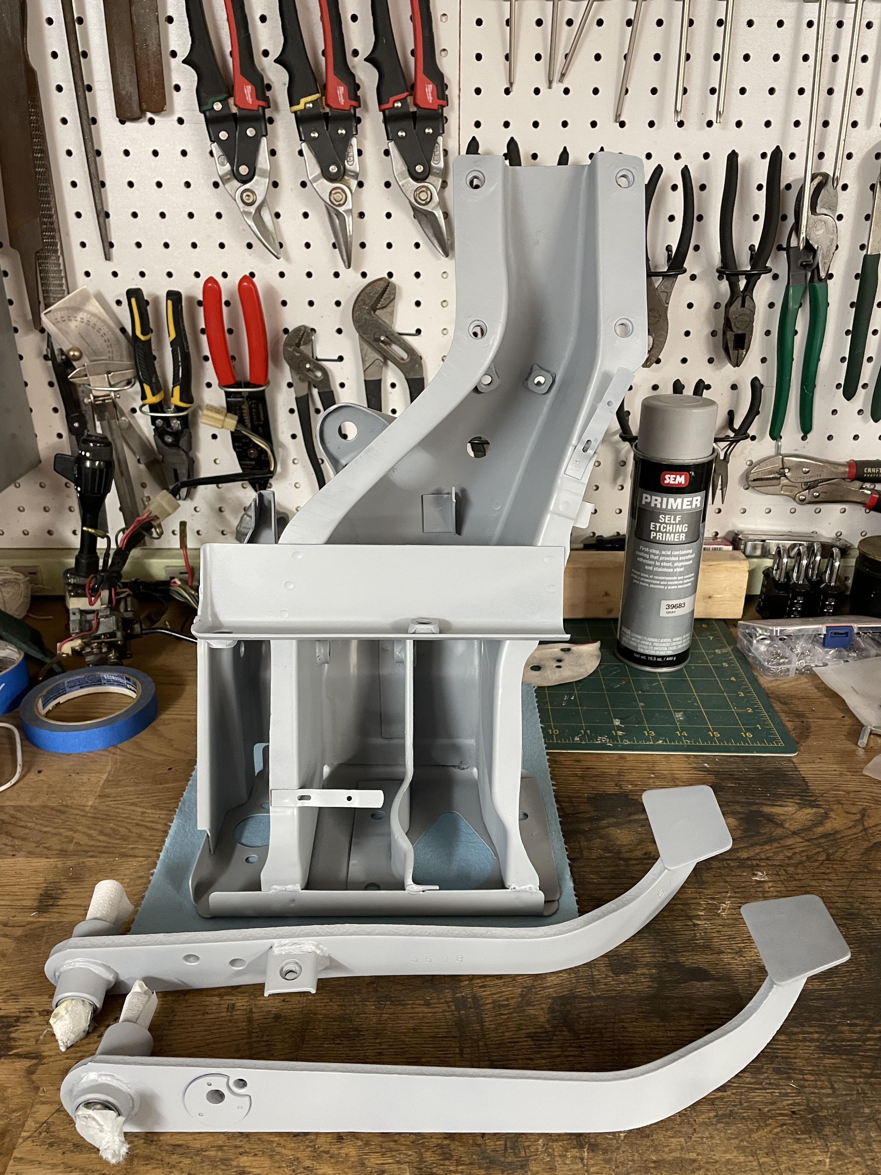
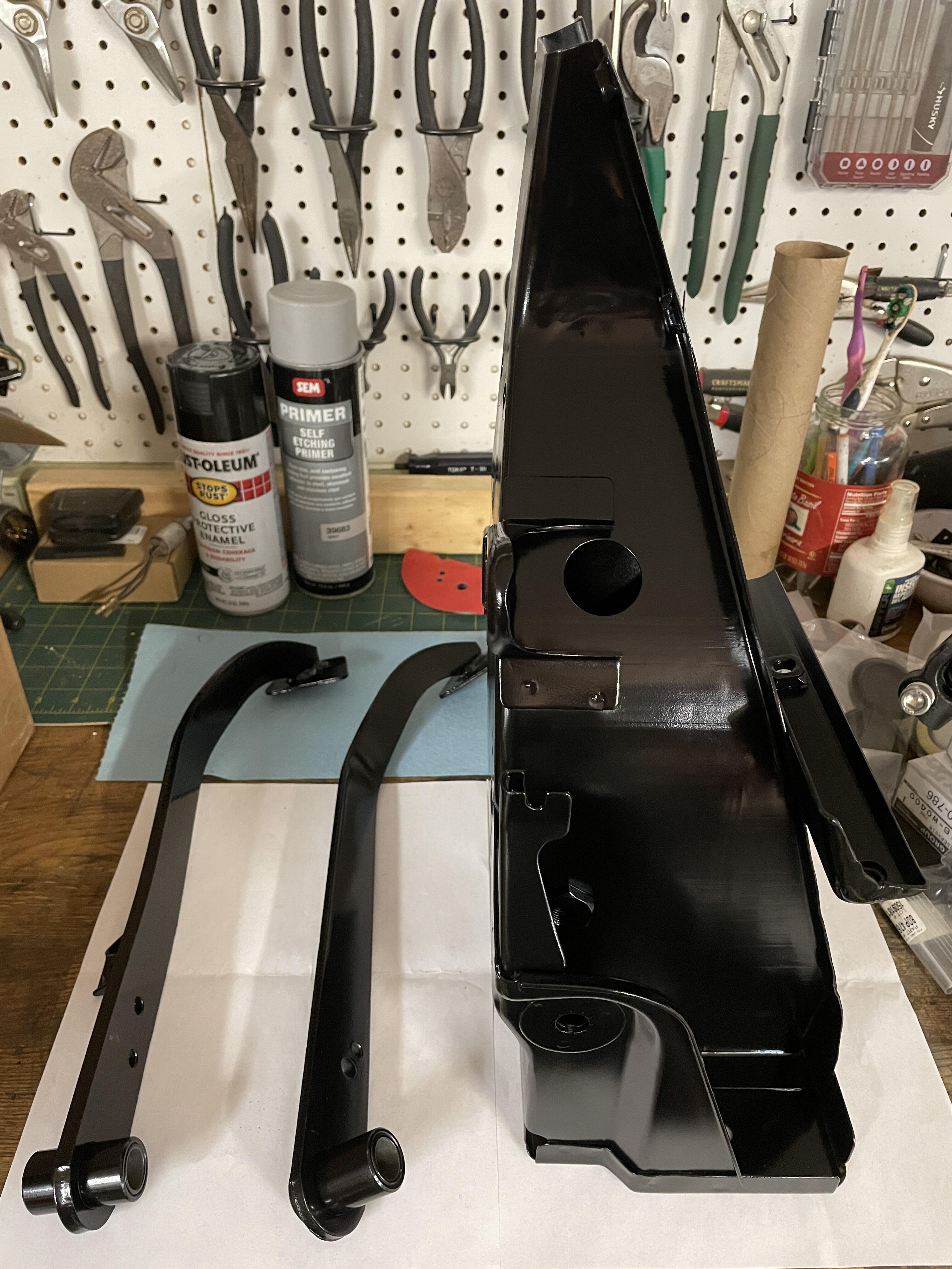
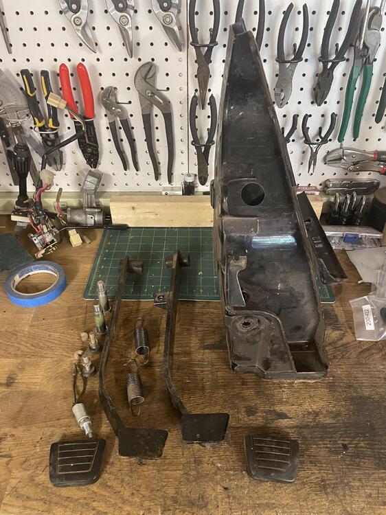
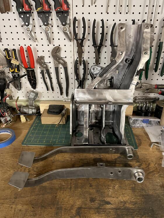
While I’m working on the wiring I have also been reconditioning parts. Here’s the pedal box: New foot pads and brake switch. Otherwise just reconditioned original parts.


-
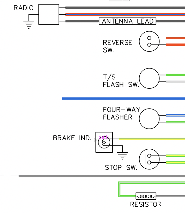
It's labeled "Brake ind." in the diagram and the wire shown is yellow with blue. It's also Yellow w/ Blue on pages BE-5 and BE-6 in the FSM diagram, conflicting with page BE-2.
-
I think I found the answer to the yellow w/ green wire question: apparently it's from a low brake fluid/pressure sensor to the e-brake light on the dash.
-
Thank you for getting in there and checking! I’ll take this back and start chasing the wires to see where things connect on the other end. Maybe that will clear it up.
-
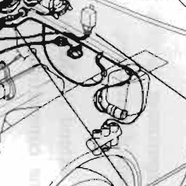
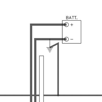
Thanks @stevej! Some of this is definitely right, but I have some questions about a few things. Is the washer motor not up on the washer tank by the firewall? If it is, I think we both has some stuff swapped around. I thought maybe these wires went to the Thermo Switch and other things that connected to the distributor on the Automatic cars. Here's a close crop of the illustration in the FSM where this stuff is. It would be between the lights and the ballast resistor, but I don't see a branch in the harness in the illustration. I'm pretty sure I have the green wires for the horns accounted for in the bundles coming out of the loom near the headlights. This one is further down the harness toward the coil. I chased it back to a splice where it joins a green wire that goes back to the other end. There are two black w/ white wires in that splice as well. These are the ones that go to the coil and stuff you mentioned. There is a black wire running to a ground next to the battery in the wiring diagram. Do you think it's this one? (Why the hell would someone cut that!?!) I am wondering if this whole mess actually goes to the washer tank and what I have labeled as the washer tank wire goes somewhere else. Here's where this is in the FSM illustration: It would make sense that this thin branch would be this part given how long it is. However, if it is some of these other things are not what I have them labeled now.

-
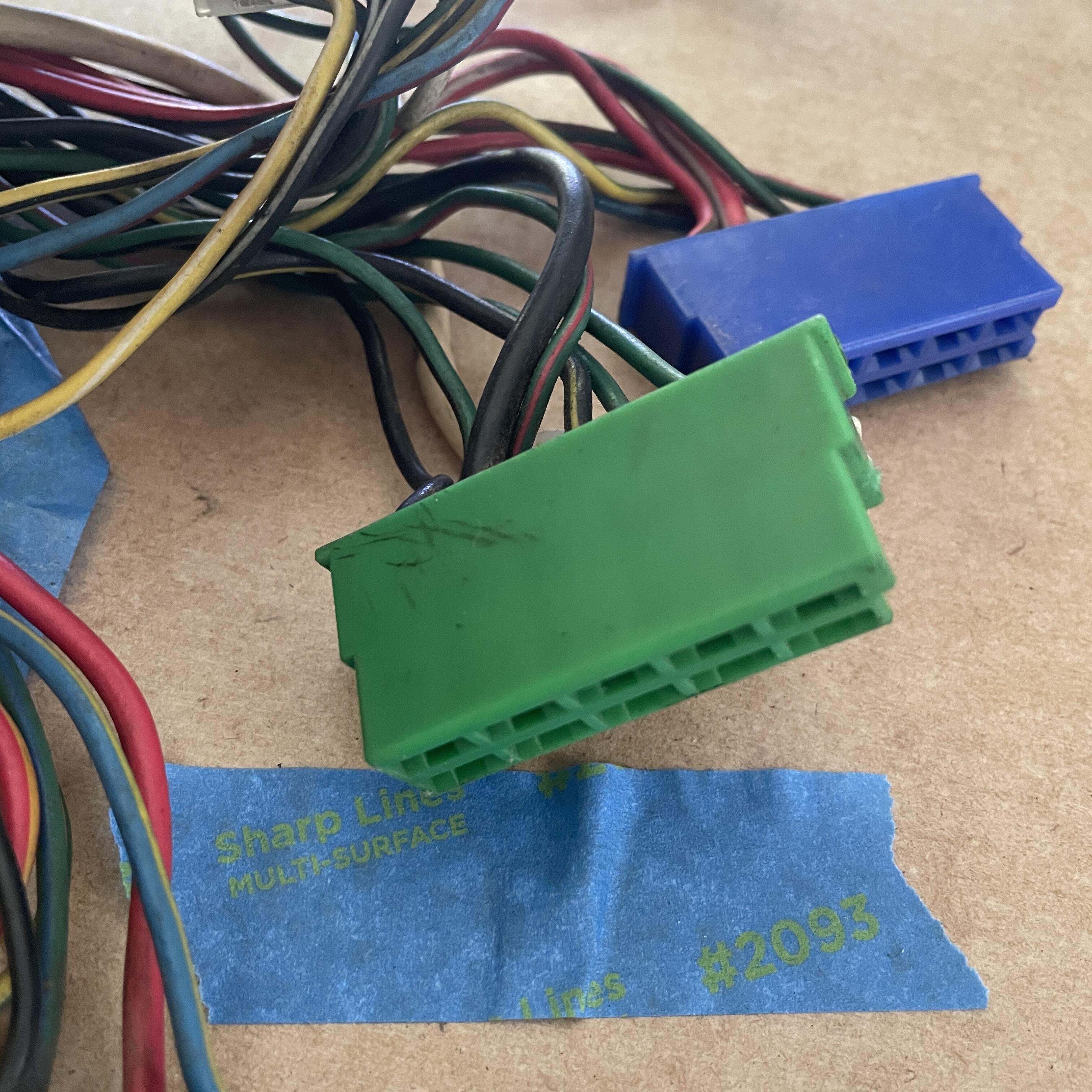
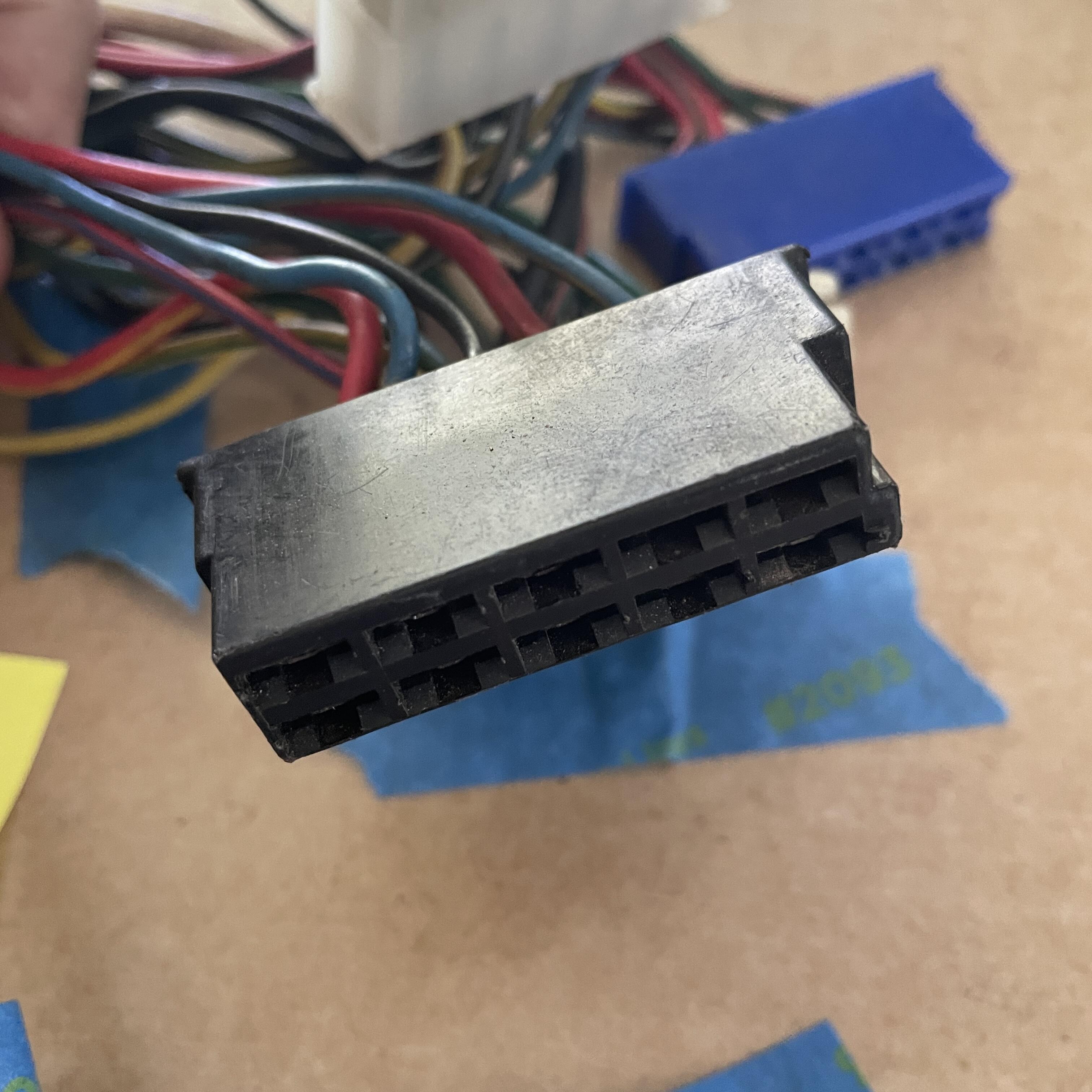
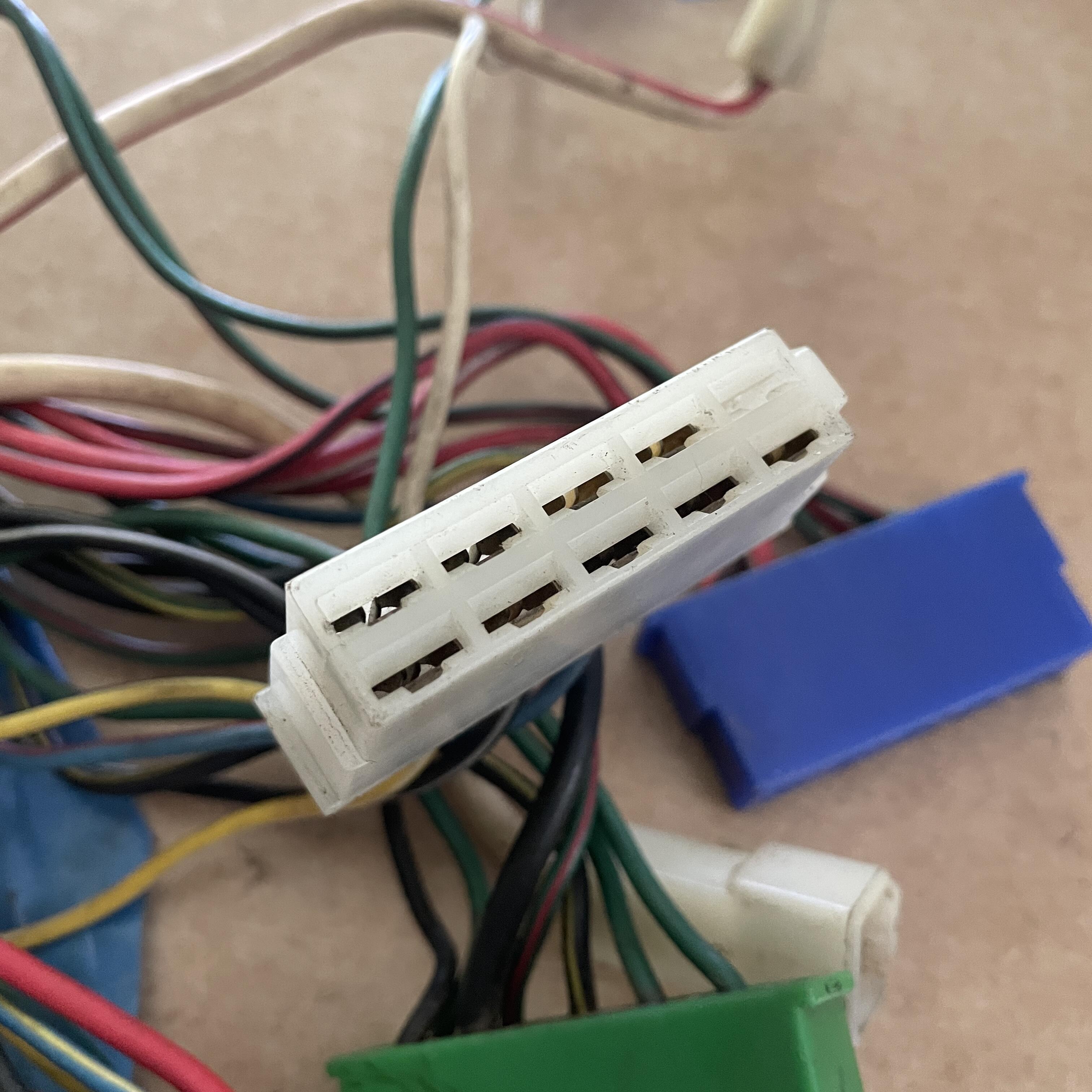
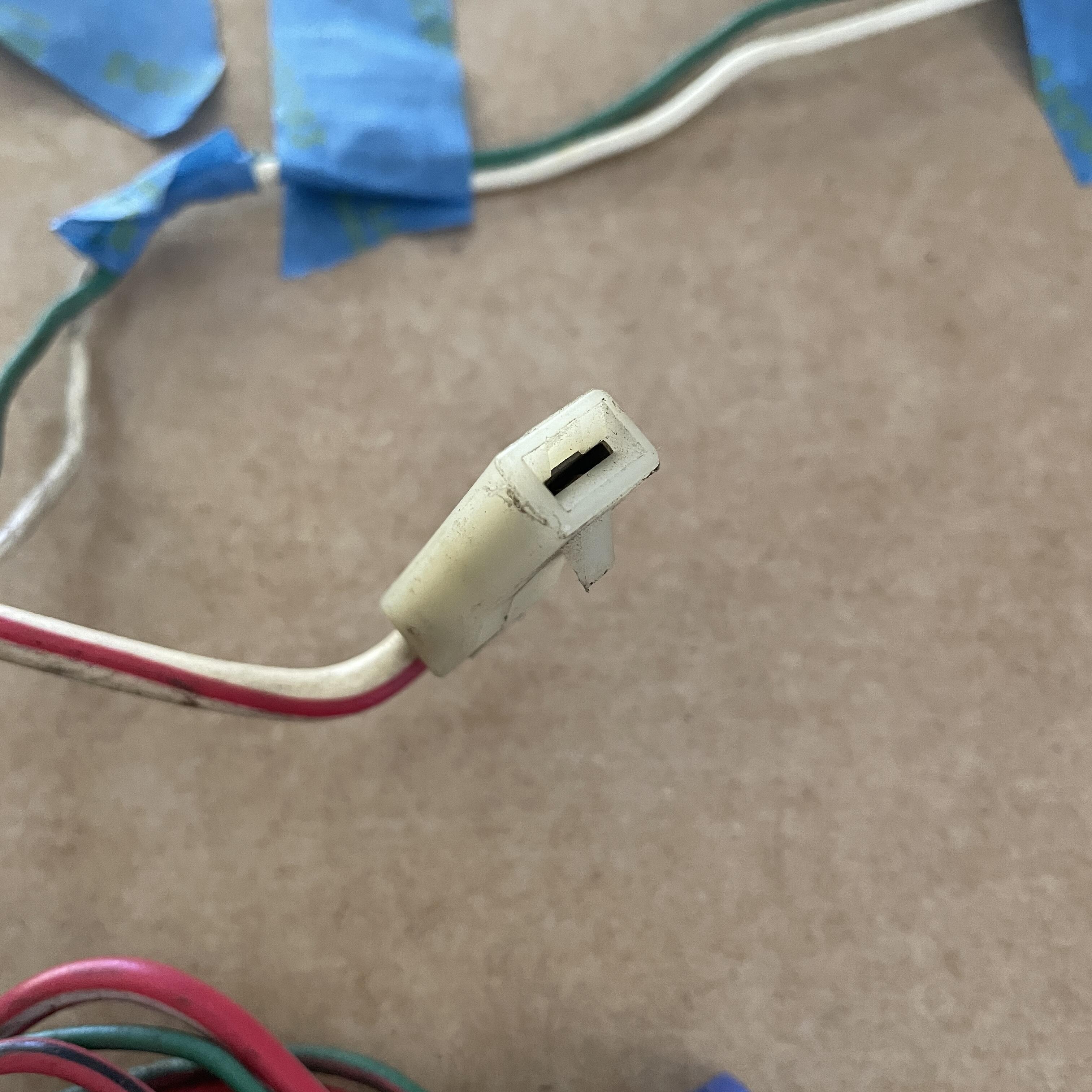
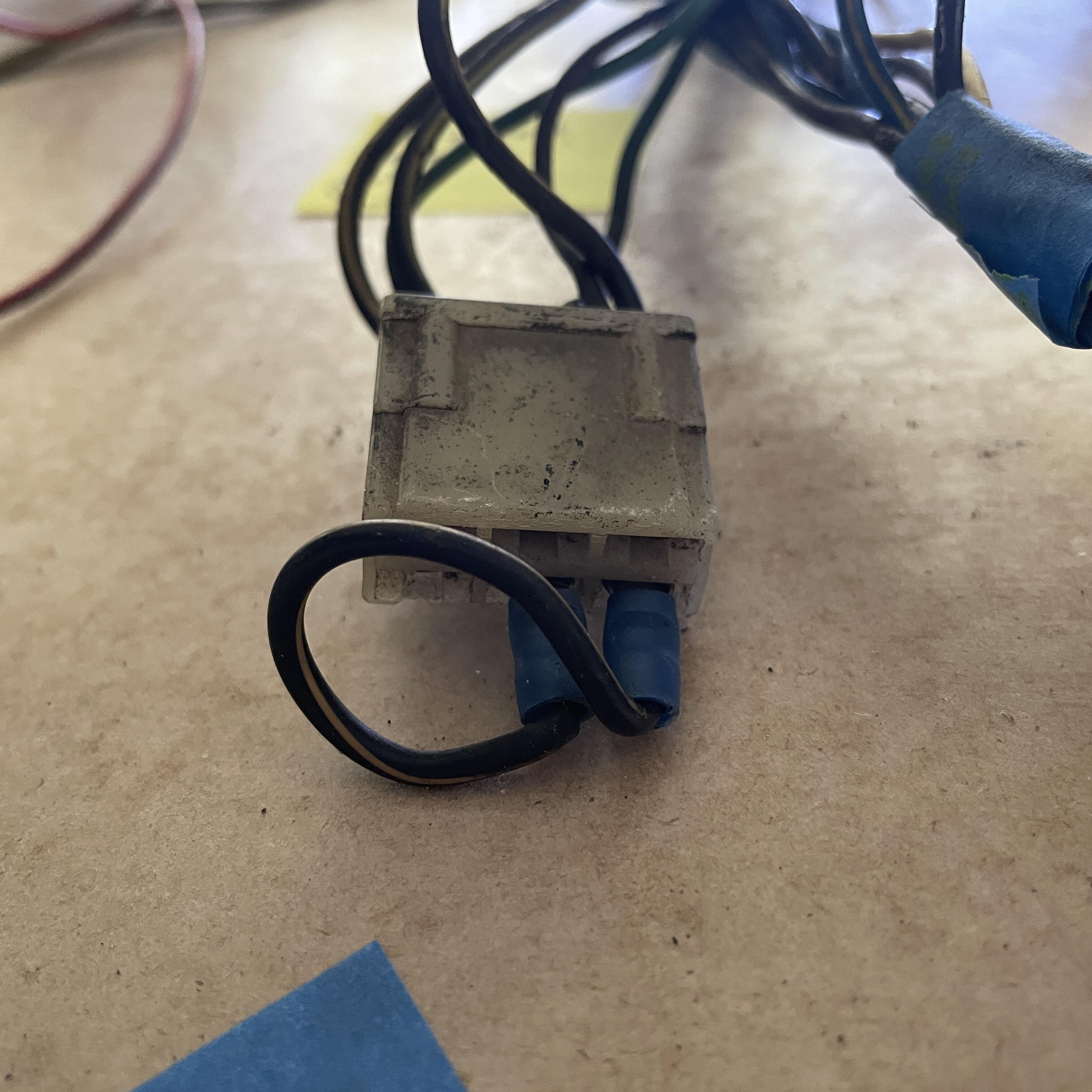
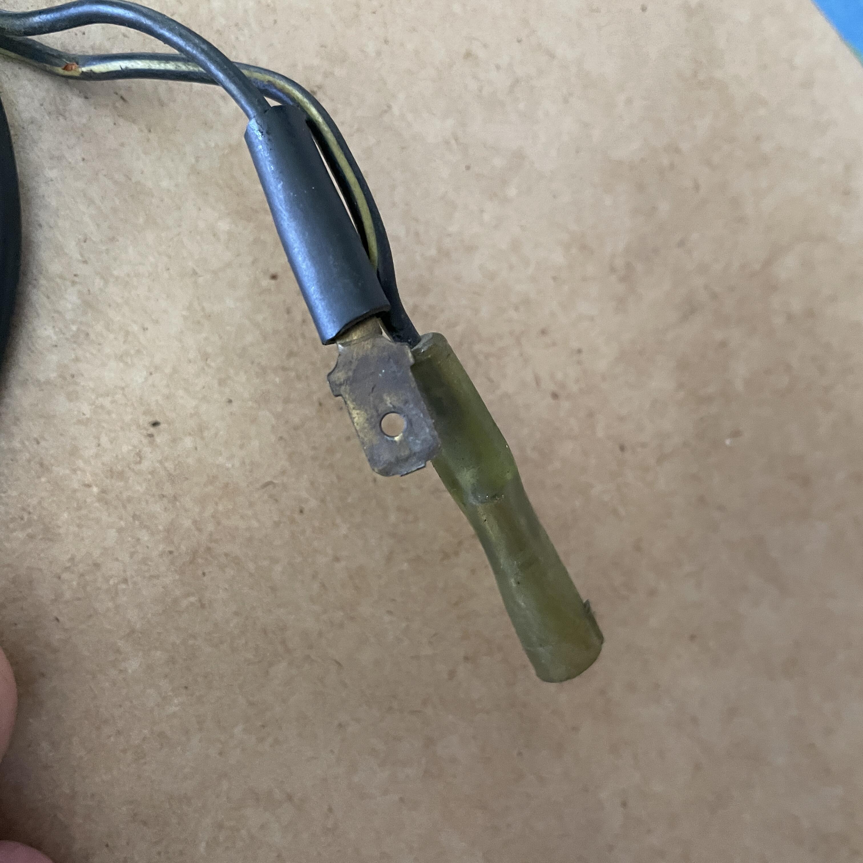
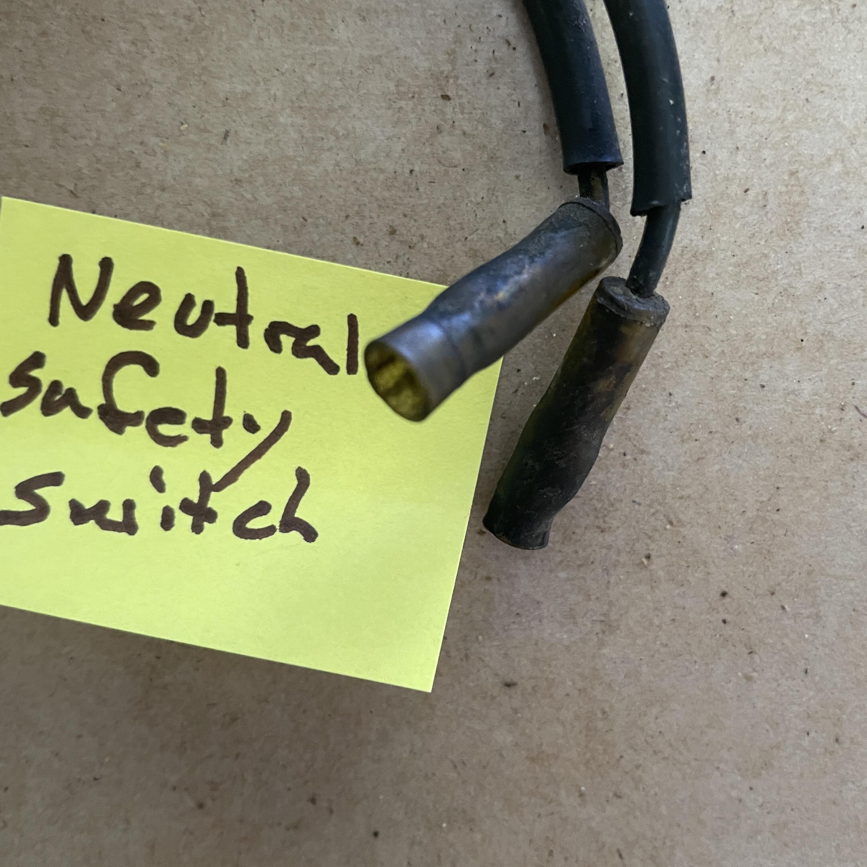
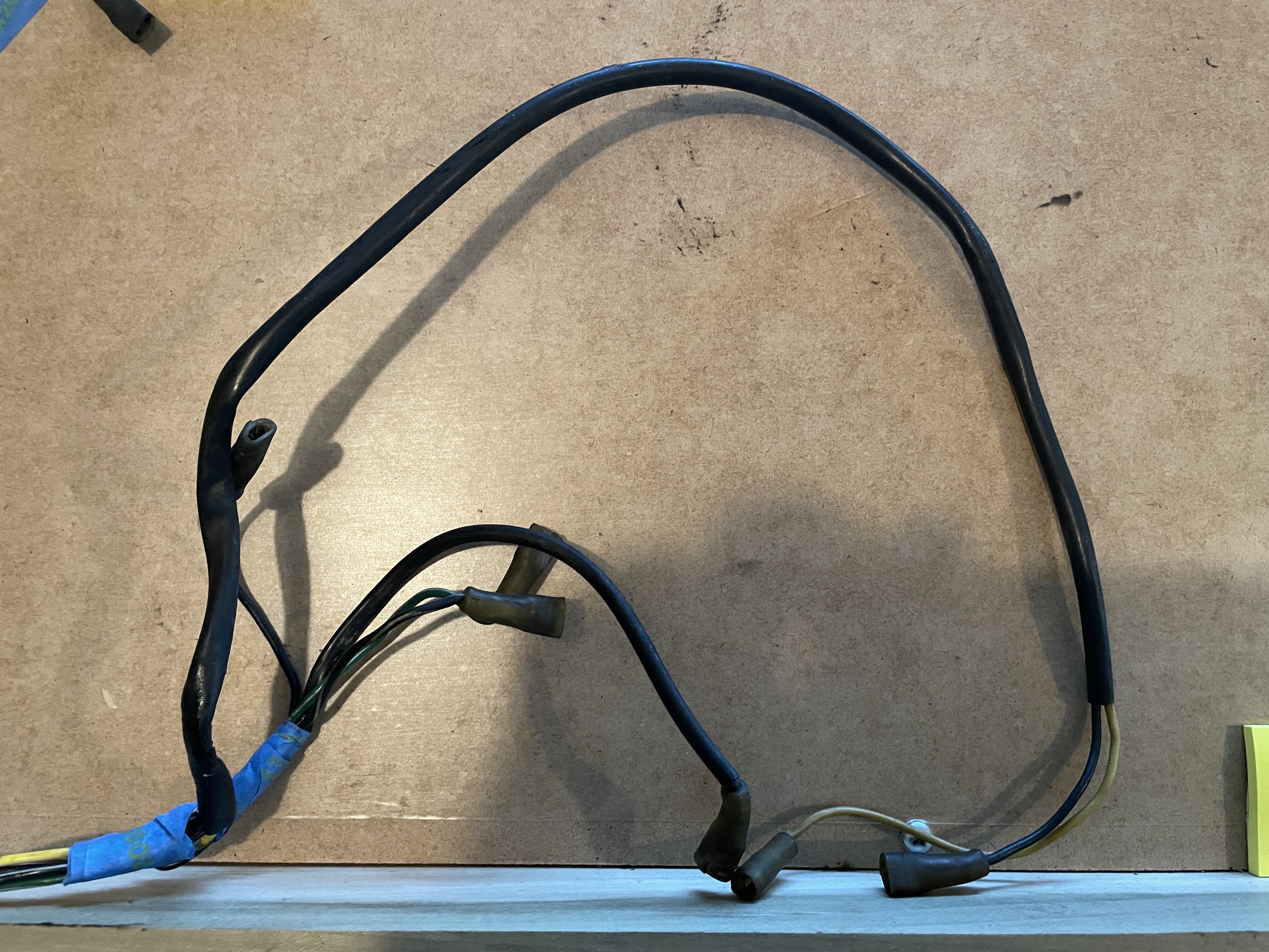
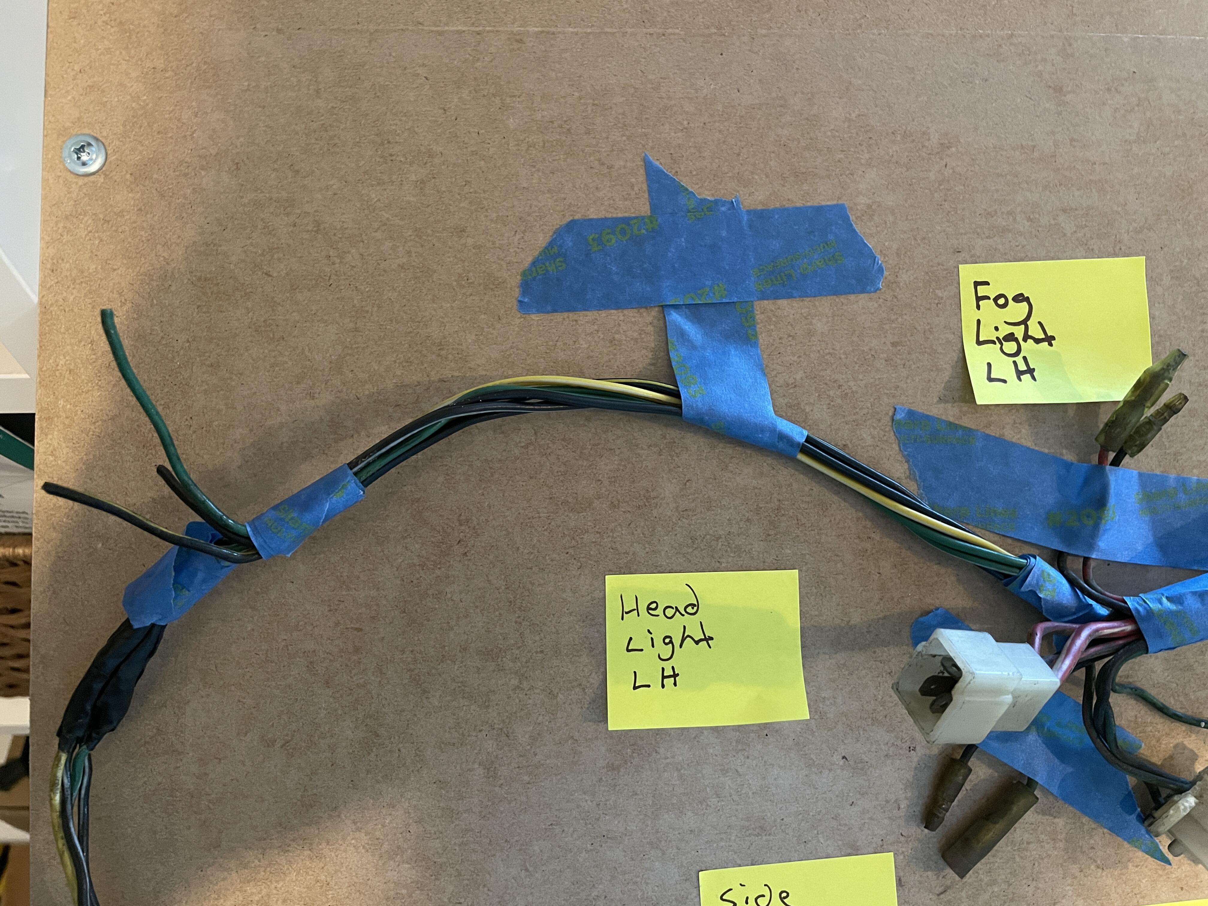
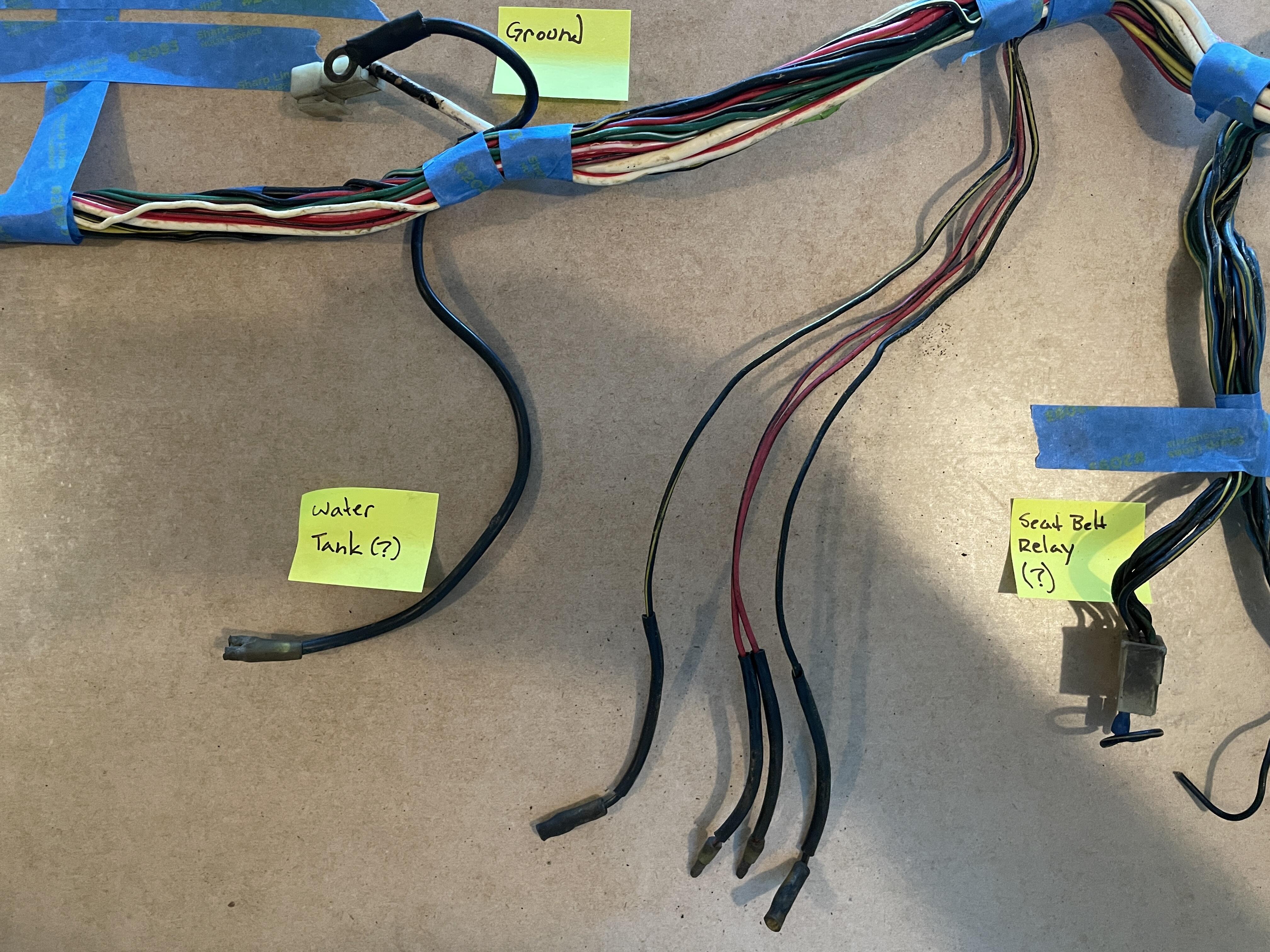
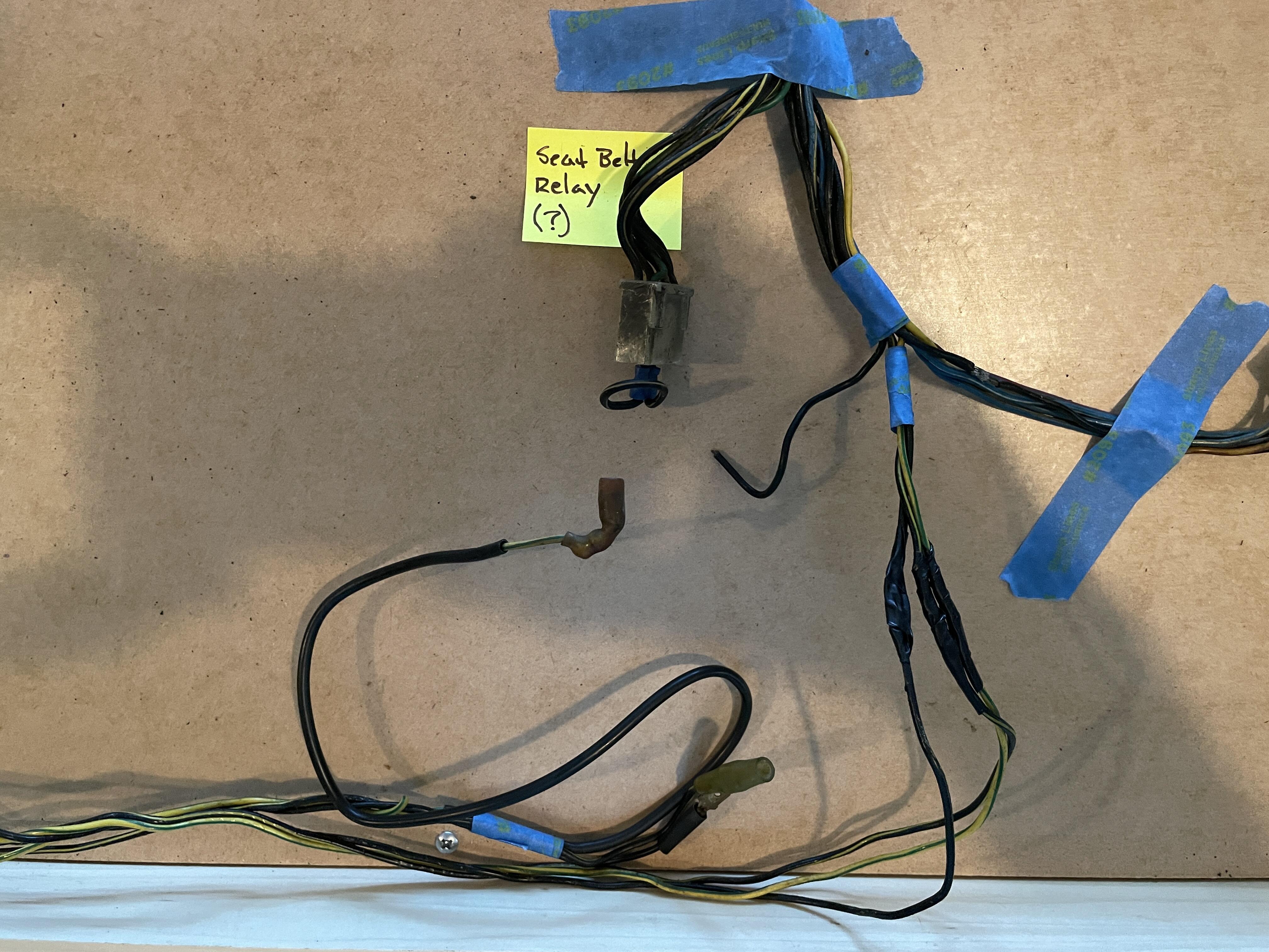
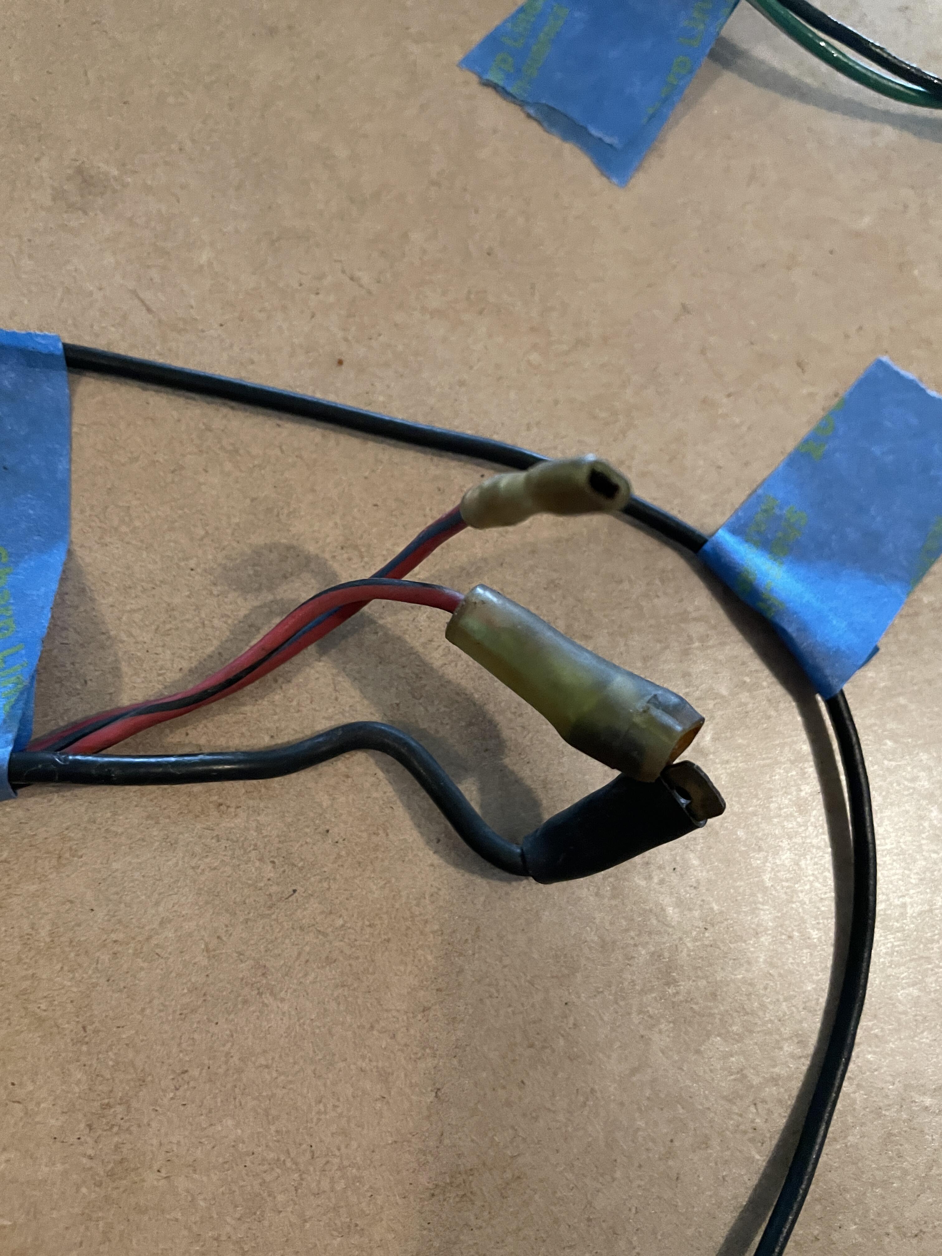
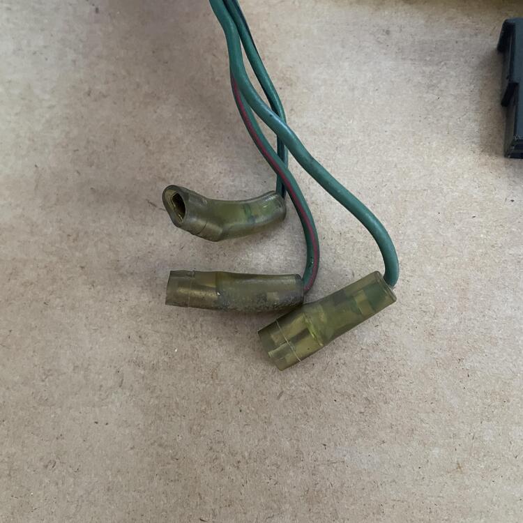
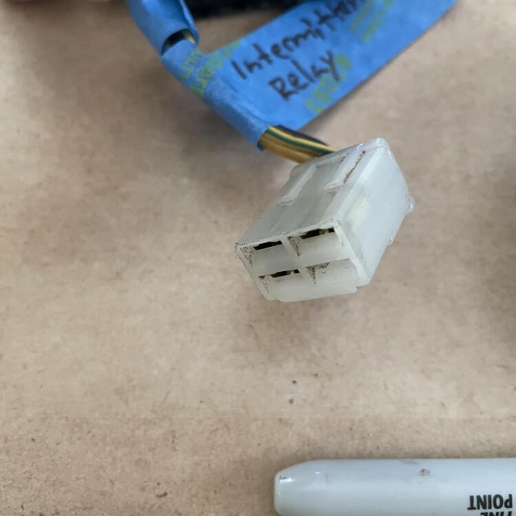
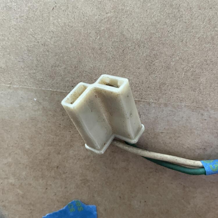
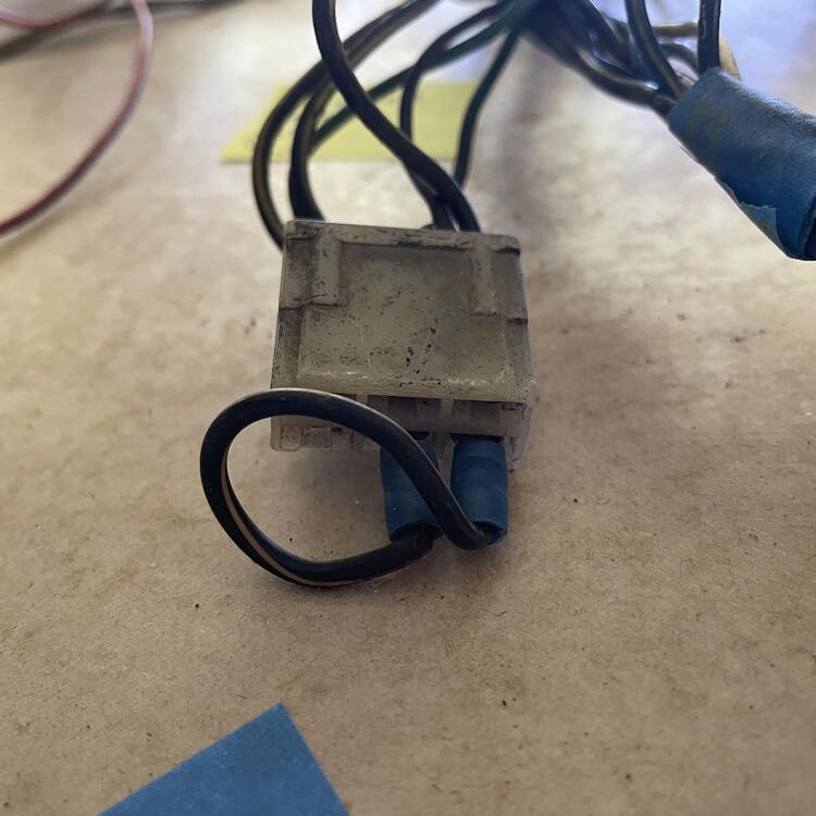
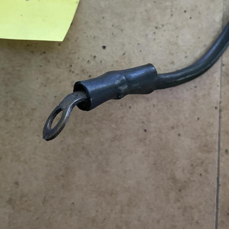
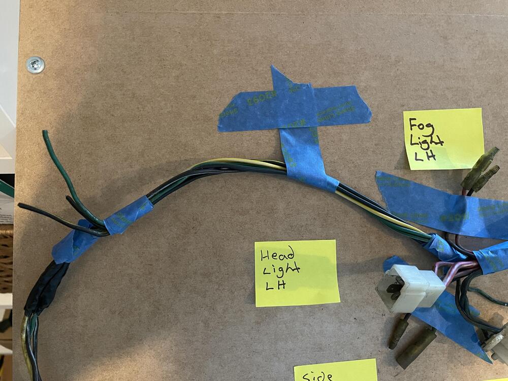
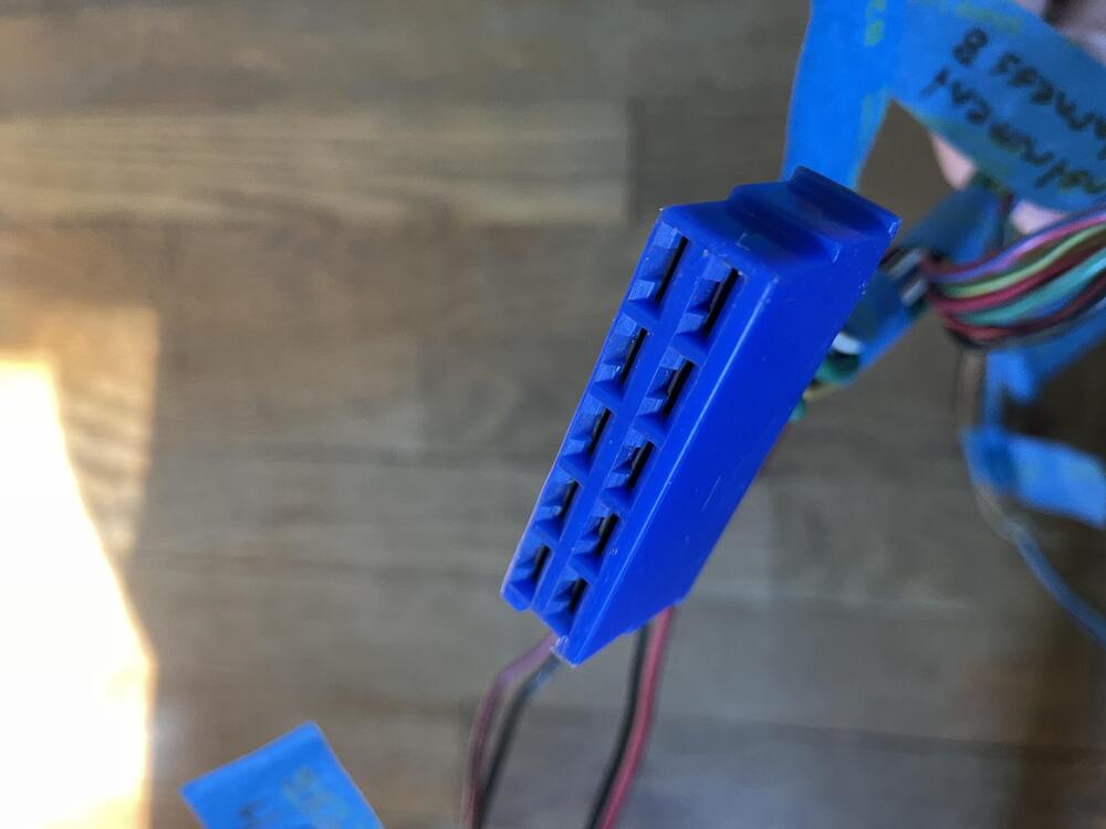
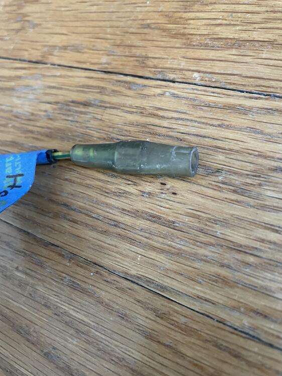
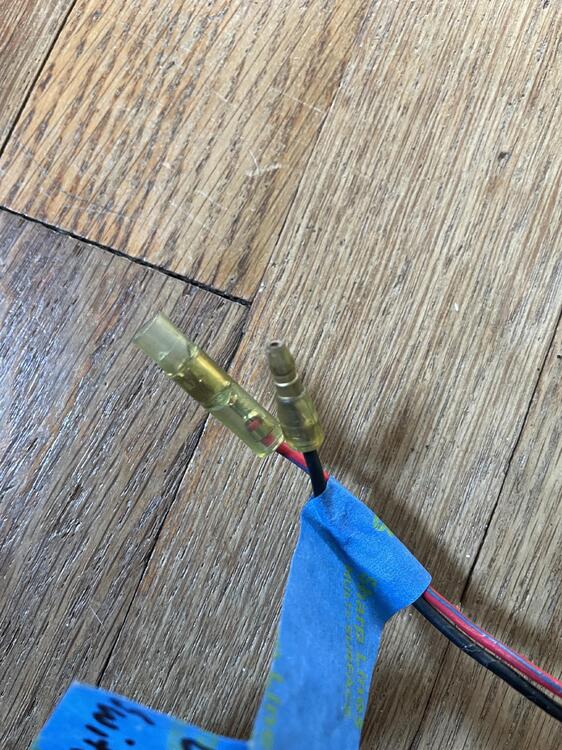
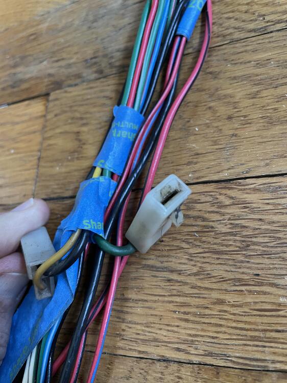
Okay, I officially need help. I have 14 wires in this harness I cannot identify at all, and 5 that I think I have right but am not 100% sure about. Starting at where this harness connects to the dashboard harness, here is a list of what I have identified already: Instrument Harness A through D, To Dash Harness A from Alternator, To Dash Instrument Harness B from Starter Motor, Horn Relay, Intermittent Relay, and Hazard Wiper Motor Starter Motor, and Starter Ground Oil Pressure Switch, Alternator, and Alternator Ground Voltage Regulator and Condenser Inspection Light Side Marker Lamp RH, Parking & T/S & Side Front RH, Head Light RH, Fog Light RH, and Horn RH Horn LH, Fog Light LH, Parking & T/S & Side Front LH, Head Light LH, and Side Marker Lamp LH --- So, working from the end furthest from the firewall toward the dashboard connectors, this is what I am looking at: I have a yellow wire ending in a female bullet connector sharing a sleeve with a black wire ending in a female spade connector That black wire extends to where the yellow wire merges into the harness and has another female spade connector At that same point I have a green w/ white wire and a black w/ white wire, both ending in female spade connectors There is also a longer black w/ white wire ending in a female spade connector and shrouded in a black sleeve Further up the harness, about 10 inches from the bundle of wires for the lights on the left side of the car, I have 3 wires that have been cut: black w/ yellow, green, and black. See the far left side of the following image. The next mystery is a bundle of 4 wires that emerges between the bundle for the starter and the thick branch of wires that holds the wiper motor connector, among others. There are 2 red w/ black ending in male bullet connectors and 2 black w/ yellow ending in female bullet connectors. See the middle of the image below. (Also, can someone confirm that that is the water tank wire?) Lastly, I have two 4 wires emerging from that thick branch that holds the wiper motor connector and what I think is the seatbelt relay (automatic only). There is a black wire that is on its own and has been cut. There is also a bundle of 3 wires: black ending in a male spade connector, black w/ yellow ending in a female spade connector, and yellow with green ending in a female bullet connector. This bundle of wires is about 6 1/2 feet long, and the diagram does not show any yellow w/ green wires. (Can someone confirm that that is the seat belt relay connector?) --- So yeah. That's the hangup on finishing this step of the project. If anyone has any idea what these wires are for, please let me know. It is entirely possible that these were modifications the previous owner made, but I am hopeful that we can solve this collectively.


-
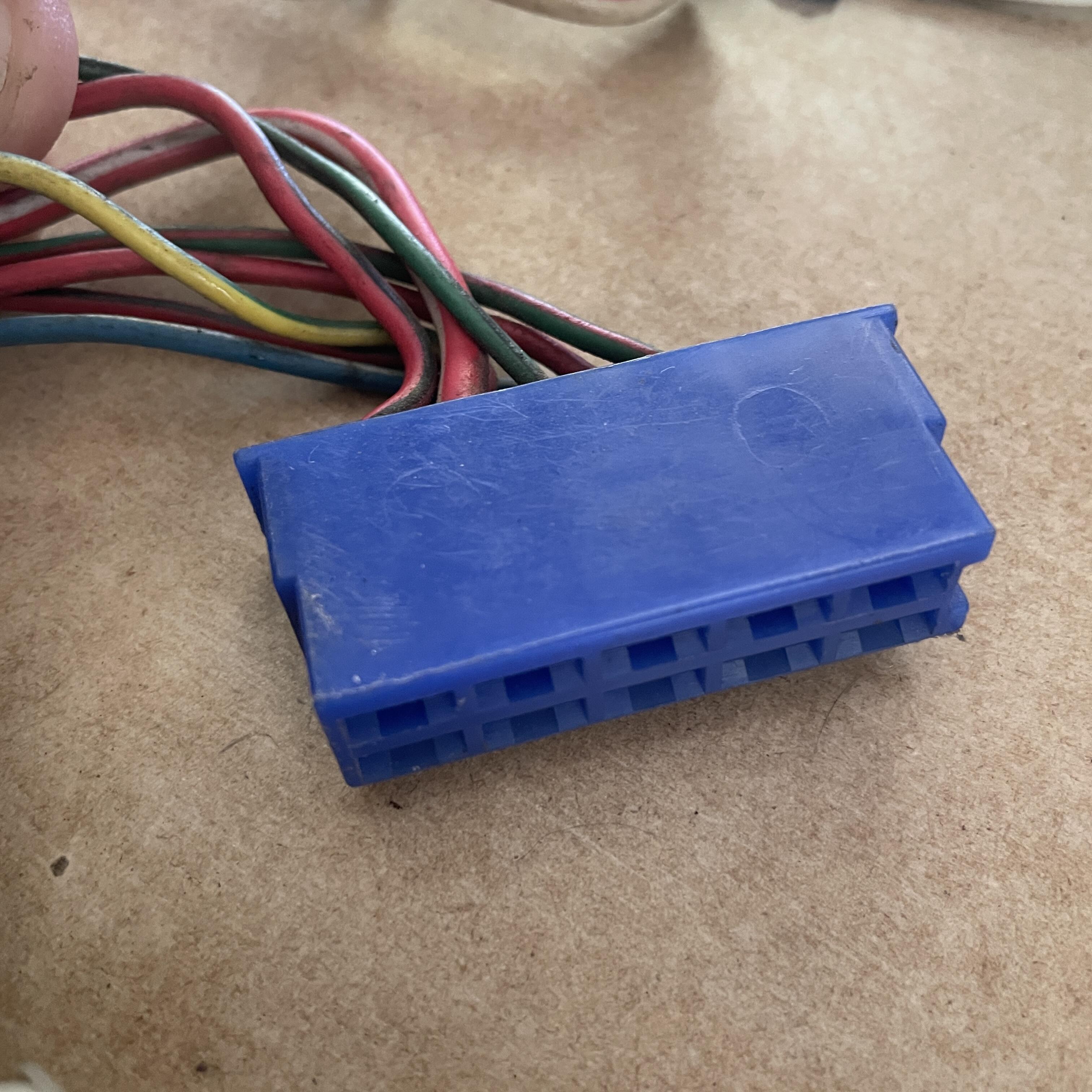
Well, I am pretty sure that my engine harness is for an automatic, not the manual harness I need. It has a 6-prong plug (G, B, B, BY, BY, BY) and a long branch with a yellow/blue wire. In the diagram that wire goes to the inhibitor. Both of these are automatic only. Not a crisis, because it was damaged and messed with in a number of places, but it does make using this as a guide to build my new one significantly harder.
-
You may have noticed a few things I marked in Red in the last post. These were wires that differed from what I have in the Factory loom I disassembled in the wiring diagram. Well, I have a few more for the engine bay. I still have a lot of wire chasing and investigation to do, but I can point out two things: 1. The Throttle Opener Relay is missing from the wiring diagram I downloaded, but it is in the FSM wiring diagram for 1973 cars with manual transmissions (bottom left hand corner near the coil). 2. The 10-pin clips are differing pretty substantially this time. I am not surprised by a couple of wires being different colors, but also, the White and Black connectors are swapped from what is in the FSM and I am missing a wire in each of the other two. I need to find out somehow if these were removed or just never there in the first place. Maybe this will become apparent after I finish chasing the wires. Component Connector Color Connector Style Direction # of Pins # of Wires Diagram Wire Color Sample Wire Color Instrument Harness A Blue 10-Prong F 10 9 Red w/ Black Red w/ Black Red w/ White Red w/ White (Heavy) Green w/ Black Green w/ Black Green w/ Red Green w/ Red – – Yellow w/ Green Yellow w/ Green Red w/ Black Red w/ Black Black w/ Yellow – Red Red Blue w/ Yellow Blue w/ White Instrument Harness B Green 10-Prong F 10 8 Black Black Black Black (Heavy) Green w/ Black – – – – – Green w/ Black Green w/ Black Green w/ Red Green w/ Red Blue Black w/ Yellow Green Green Green Green Instrument Harness C White Black 10-Prong F 10 8 Yellow w/ Green Yellow w/ Green Blue Blue Black Black – – – – Red w/ Yellow Red w/ Yellow Red w/ Blue Red w/ Blue Green w/ Blue Green w/ Blue Red Red Blue w/ Yellow Blue w/ Yellow Instrument Harness D Black White 10-Prong F 10 9 Green w/ White Green w/ White Black w/ White Black White White Green Green – – Yellow w/ White Yellow w/ White Black w/ White Black w/ White Black w/ White Black w/ White Yellow w/ Blue Yellow w/ Black Yellow w/ Red Blue w/ Red
-
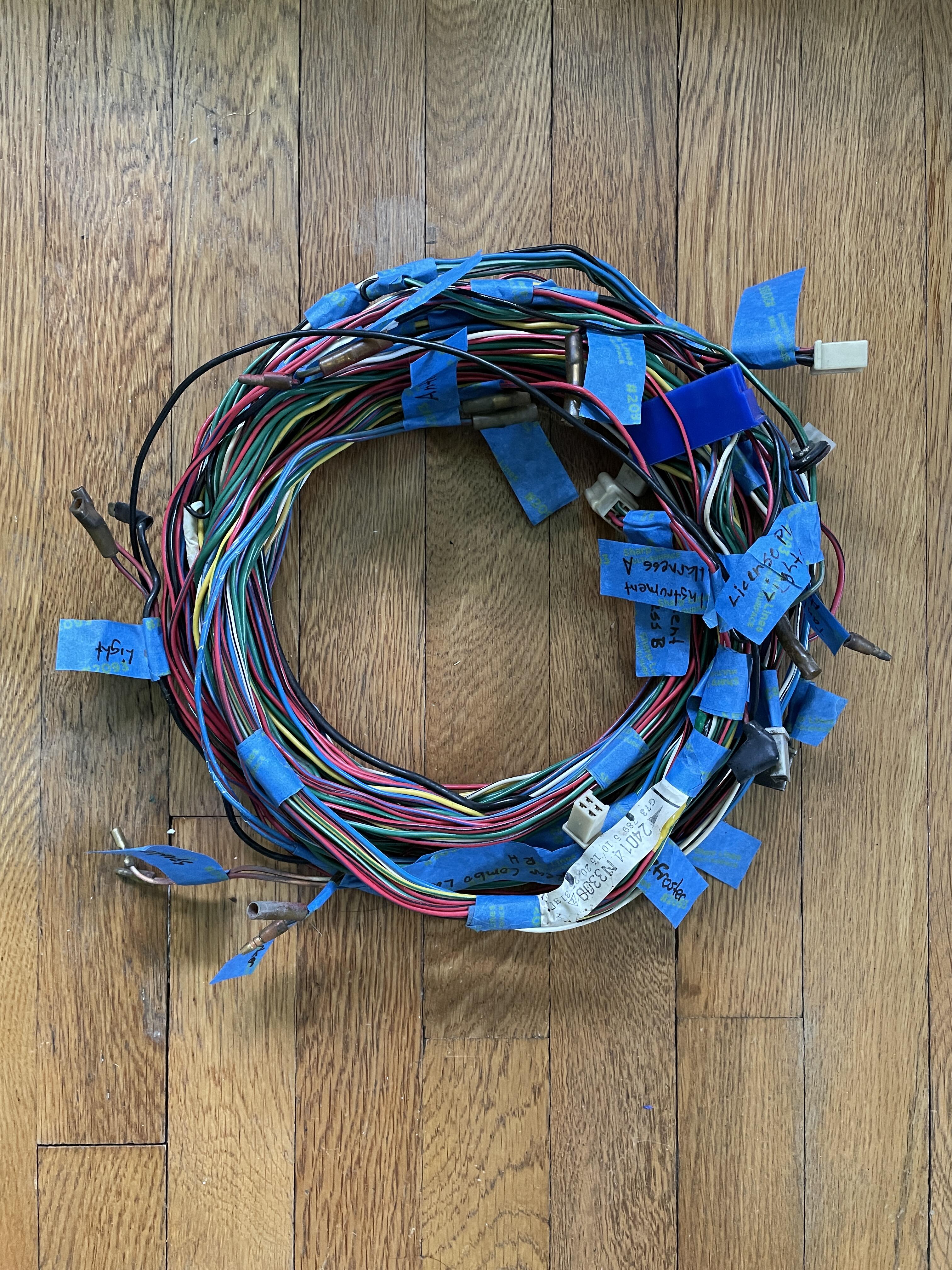
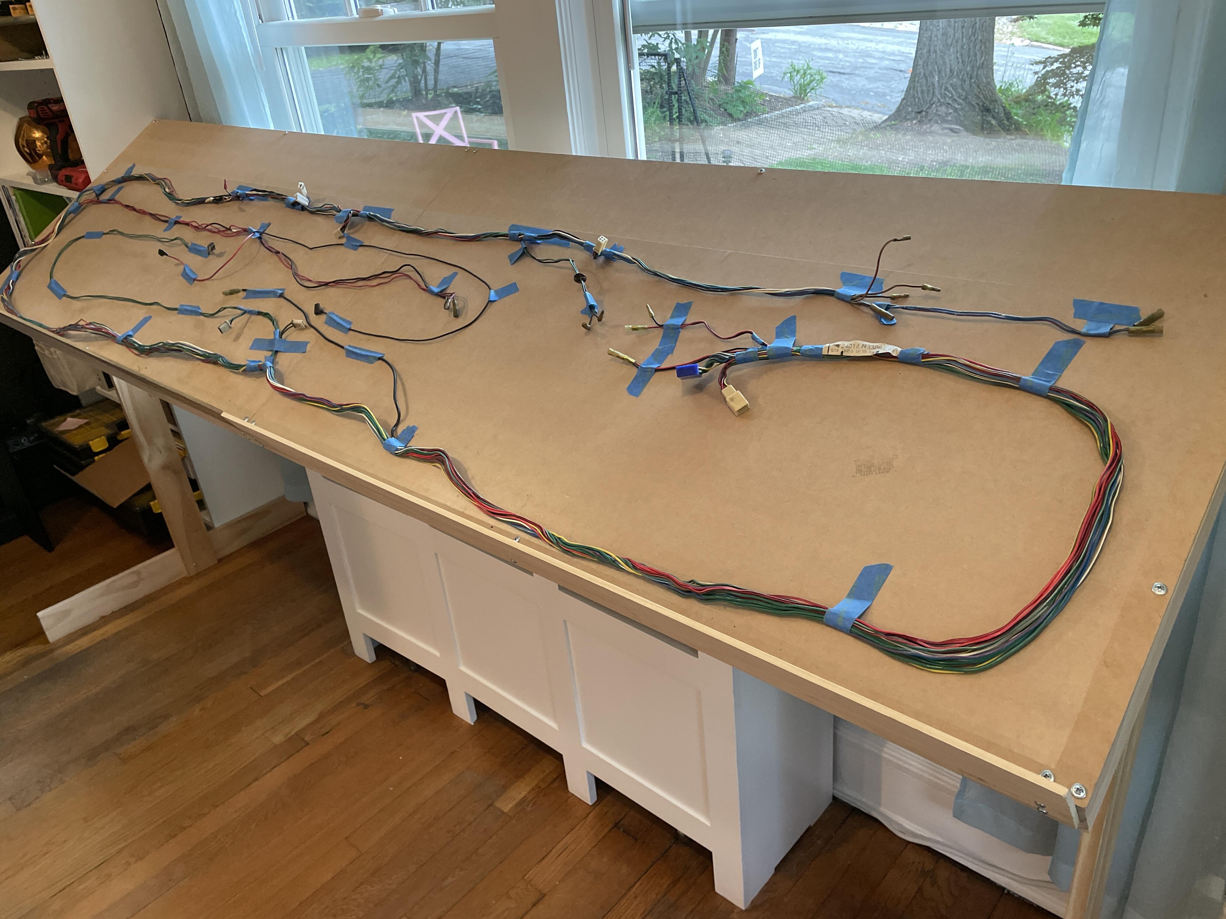
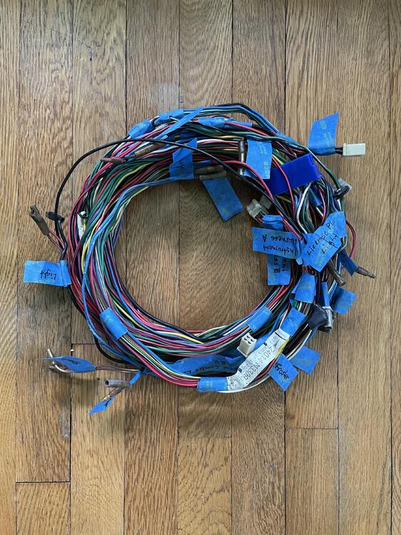
Finished the inventory of the body harness… Tagged all the connectors and checked them against the diagram. Measured the lengths and identified all of the splice points. Here’s everything I’ll need to replicate it (except the optimal wire gauge), with the splice color indicating the color tape covering the splice: 1973 240z Body Harness Inventory Position Component Conector Color Connector Style Connector Image Direction # of Pins # of Wires Diagram Wire Color Harness Wire Color Min. Feet of Wire Needed 1 Instrument Harness A Blue 10-Prong F 10 10 White w/ Black White w/ Black [See Speaker] Blue w/ Red Blue w/ Red [See Antenna] White White [See Speaker] Blue w/ White Blue w/ White [See Antenna] Yellow Yellow [See Fuel Pump] Green w/ Black Green w/ Black [R. Comb. Lamp RH] Green w/ Red Green w/ Red [R. Comb. Lamp LH] Green Green [See Belt Switches] Green Green [See Seat Switch] Green Green (Heavy) [See Fuel Pump] 2 Instrument Harness B White 6-Prong M 6 6 Red w/ Black Red w/ Black (Thick) [See Rear Glass Defroster] Red w/ Blue Red w/ Blue [See Room Light] Yellow w/ Green Yellow w/ Green [See Hand Brake Switch] Green w/ White Green w/ White 18 (to Green Splice C) Red w/ Black Red w/ Black [R. Comb. Lamp LH] Black Black 1 (to Yellow Splice) 3 Door Switch Clear Spade F 2 2 Black Black [See Step Light Harness] Black Red w/ Black [See Room Light] 4 Step Light Harness Clear Bullet M 1 1 Black Black 2 Clear Bullet F 1 1 Red w/ Blue Red w/ Blue 1 4 Yellow Splice N/A N/A N/A N/A 2 2 Red w/ Blue Red w/ Blue N/A Black Black 5 Hand Brake Clear Spade F 1 1 Yellow w/ Green Yellow w/ Green 8 6 Green Splice A N/A N/A N/A N/A 3 3 Green Green N/A Green Green Green Green 7 Belt Switch RH White 3-Prong Mini F 3 2 Green w/ Black Green w/ Black [See Seat Switch] Green Green 7 7 Green Splice B N/A N/A N/A N/A 3 3 Green Green N/A Green w/ Black Green w/ Black 8 Seat Switch White 3-Prong Mini F 3 2 Green w/ Black Green w/ Black 1 Red Green 1 (from Green Splice A) 9 Belt Switch LH White 3-Prong Mini F 3 2 Green w/ Black Green w/ Black 1 (from Green Splice B) Green Green 12 9 White Splice A N/A N/A N/A N/A 2 2 Black Black N/A Black Black 10 Room Light Clear Spade F 1 1 Black Black 3 (from White Splice A) Clear Spade F 1 1 Red w/ Blue Red w/ Black 17 Black Spade M 1 1 – Red w/ Blue 17 11 Rear Glass Defroster Black Spade F 1 1 Black Black 19 Black Spade F 1 1 Red w/ Black Red w/ Black 15 12 Green Splice C N/A N/A N/A N/A 3 3 Green w/ White Green w/ White N/A Green w/ White Green w/ White 12 Rear Side Marker Light RH Clear Bullet M 1 1 Black Black 1 (from White Splice B ) Clear Bullet F 1 1 Green w/ White Green w/ White 1 (from Green Splice D) 13 Tank Sending Unit White 2-Prong w/ Clip F 2 2 Black Black 6 (from White Splice A) Yellow Yellow 14 Fuel Pump White 1-Prong F 1 1 Black Green 14 Yellow – – 14 Rear Combo Lamp RH White 4-prong Small F 4 4 Black Black 3 (to White Splice A) White w/ Black Green w/ Black 16 Green w/ White Green w/ White 2 (to Green Splice E) Red w/ Black Red w/ Black 1 (to Green Splice D) 14 Green Splice D N/A N/A N/A N/A 2 2 Red w/ Black Red w/ Black N/A Red w/ Black Red w/ Black 15 Green Splice E N/A N/A N/A N/A 3 3 Green w/ White Green w/ White N/A Green w/ White Green w/ White Green w/ White Green w/ White Green w/ White Green w/ White 15 License Plate Light Clear Bullet M 1 1 Black Black 2 (to White Splice B ) Clear Bullet F 1 1 Black Green w/ White 1 (from Green Splice E) 16 Rear Combo Lamp LH White 4-prong Small F 4 4 Black Black 1 (to White Splice B ) White w/ Black Green w/ Red 18 Green w/ White Green w/ White 1 (from Green Splice E) Red w/ Black Red w/ Black 18 16 White Splice B N/A N/A N/A N/A 2 2 Black Black N/A Black Black Black Black Black Black 17 Side Marker Light LH Clear Bullet M 1 1 Black Black 2 (from White Splice B ) Clear Bullet F 1 1 Green w/ White Green w/ Black 3 (from Green Splice E) 18 Speaker Clear Bullet M 1 1 – White w/ Black 19 Clear Bullet F 1 1 – White 19 19 Antenna Clear Bullet F 1 1 Blue w/ Red Blue w/ Red 20 Clear Bullet F 1 1 Blue w/ White Blue w/ White 20


-
Awesome! Thank you. I just realized I may have filed this thread in the wrong place. I don’t see an electrical section but maybe one of the moderators can move it to the right place.
-
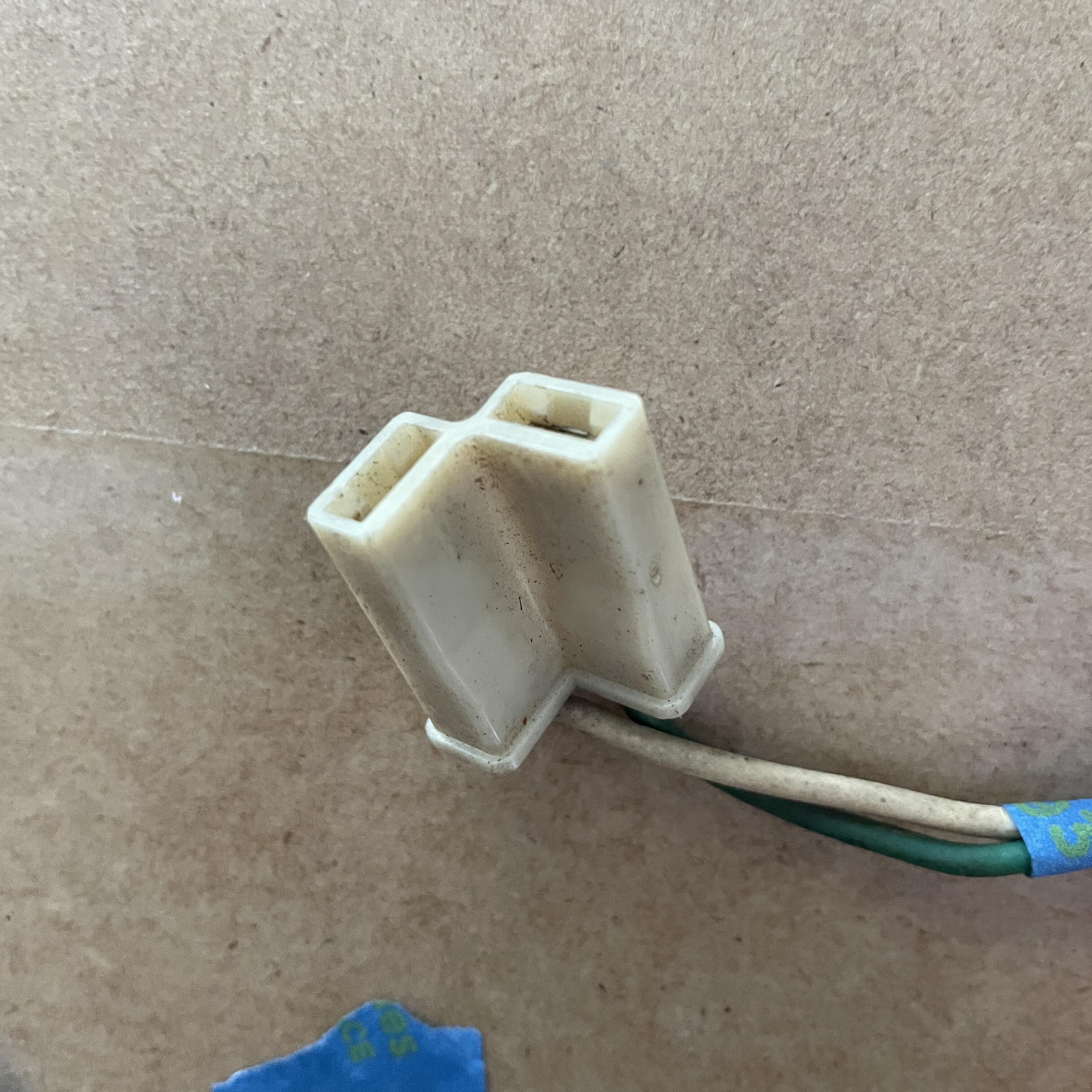
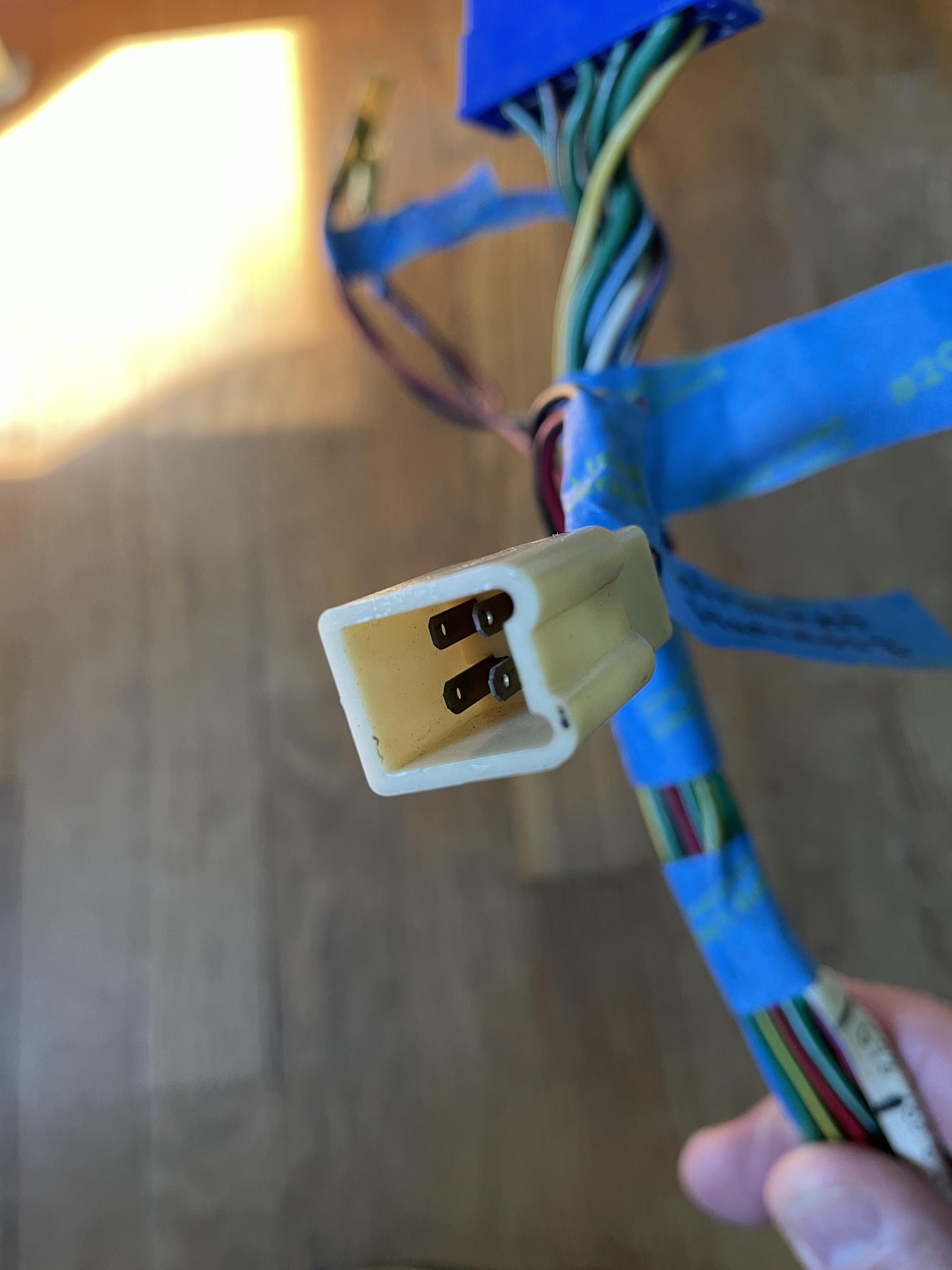
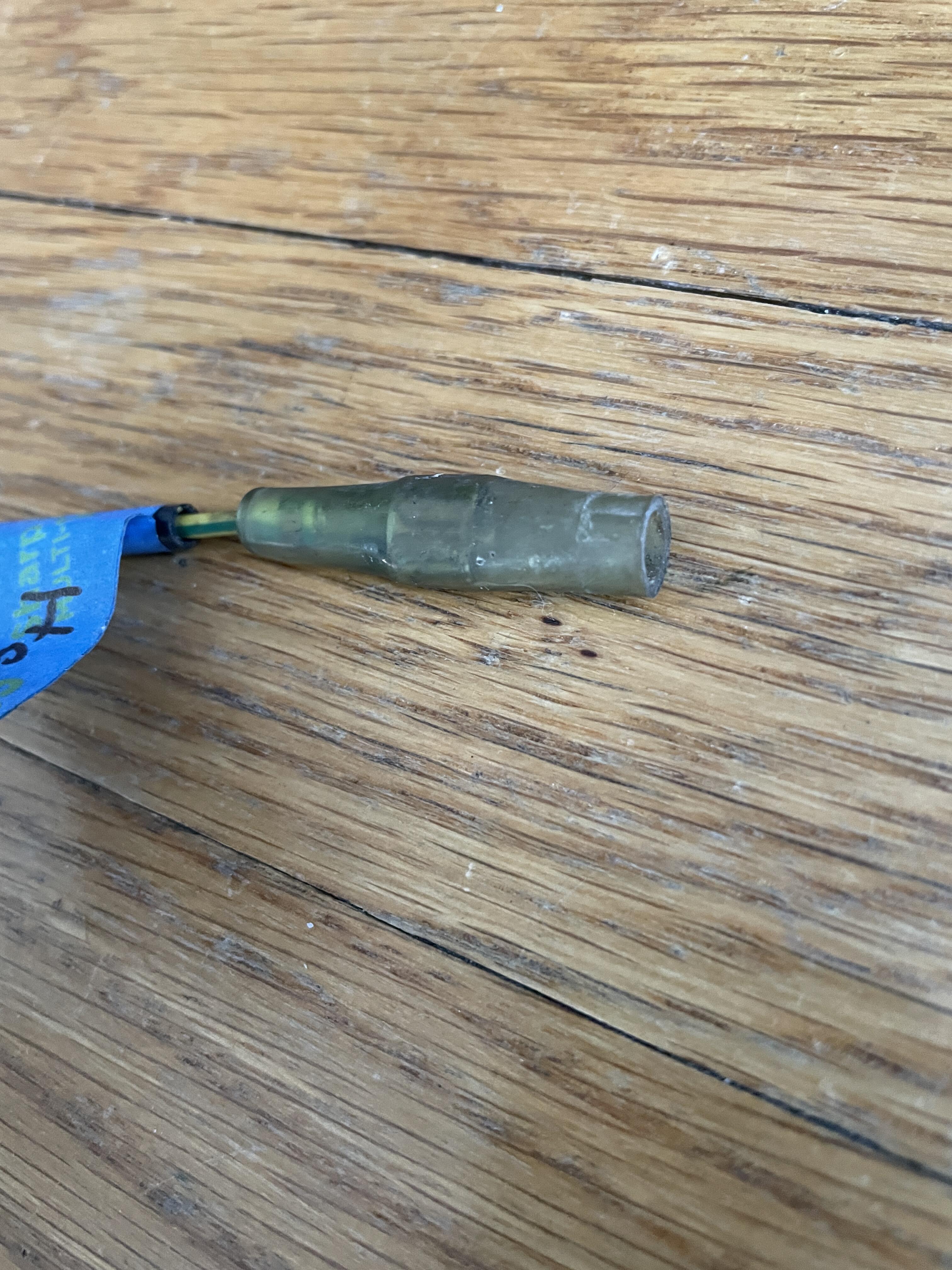
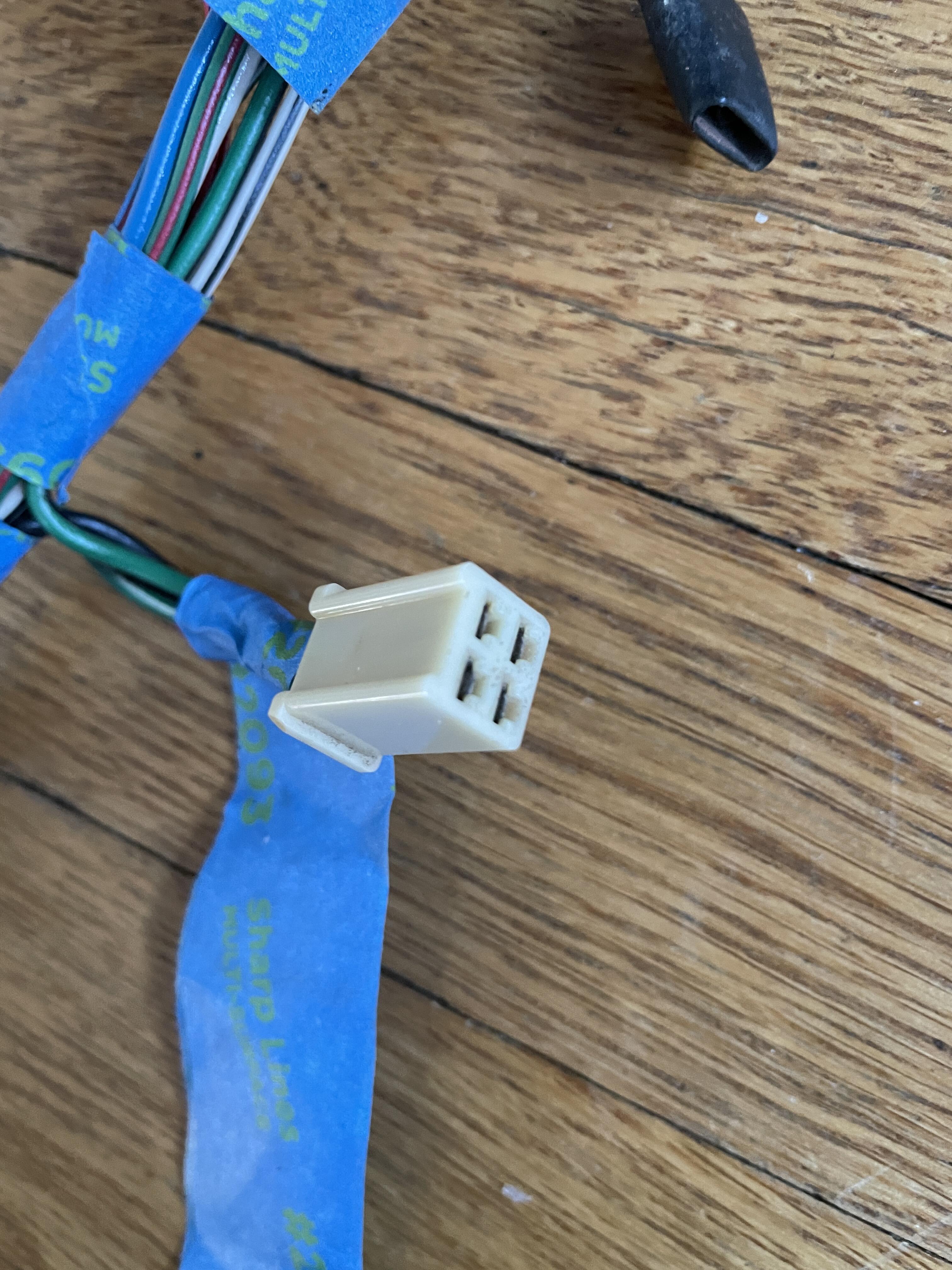
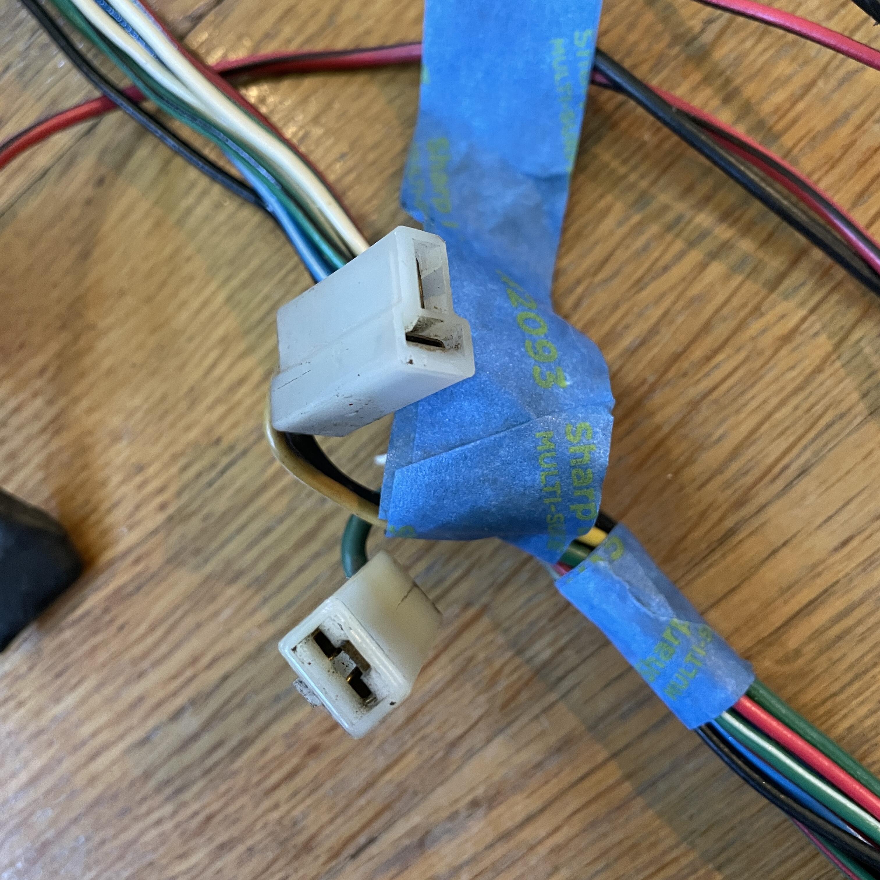
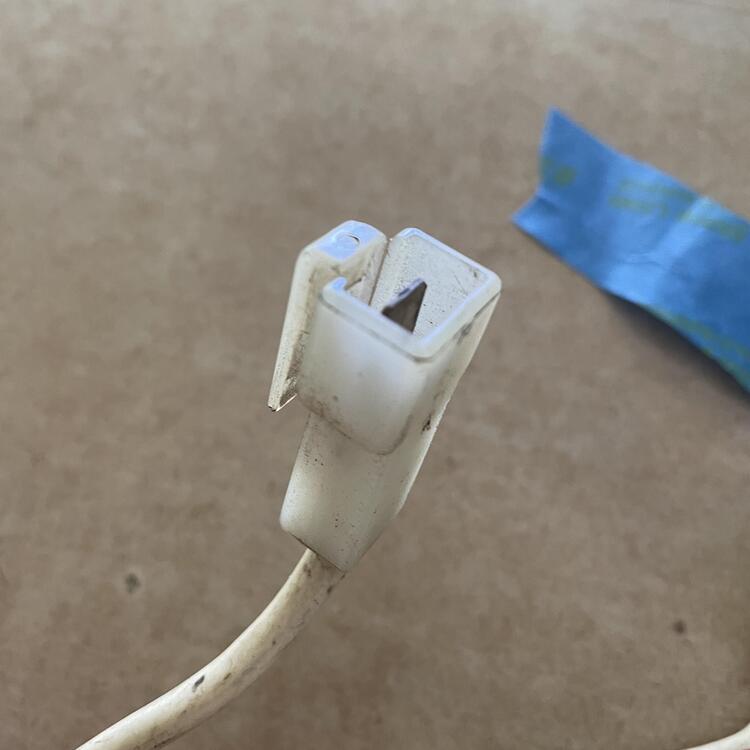
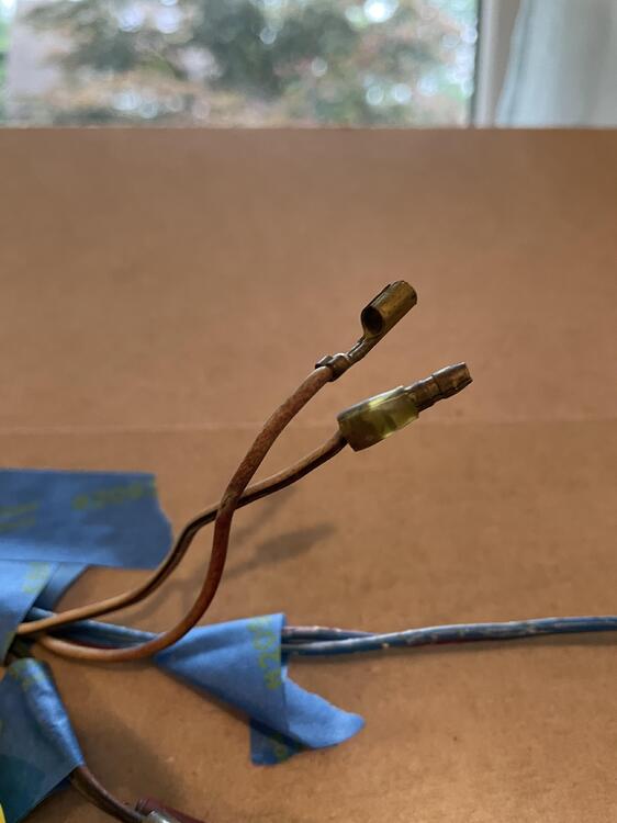
I have a question about these plugs on the body harness: The one at the top of the photo is to the fuel pump and is labeled in the wiring diagram and the FSM. It has two wires (black, yellow) and two plugs in a T arrangement. The other on is the one I can’t identify. It has one plug and one wire (green) that is a heavier gauge than all of the other wires in the harness. The connector has a tooth for a clip and the wire goes all the way back to the blue 10-pin connector that joins the dashboard harness. I checked the FSM and don’t see a label for this wire where it describes that blue connector, but it is directly across from the yellow wire in that connector, which goes to the fuel pump. Is this just a third wire for that fuel pump harness? If so I wonder why they didn’t just use a 3-plug connector. Is it for the fuel tank sending unit? That is showing as two wires (black, yellow) in the diagram.

-
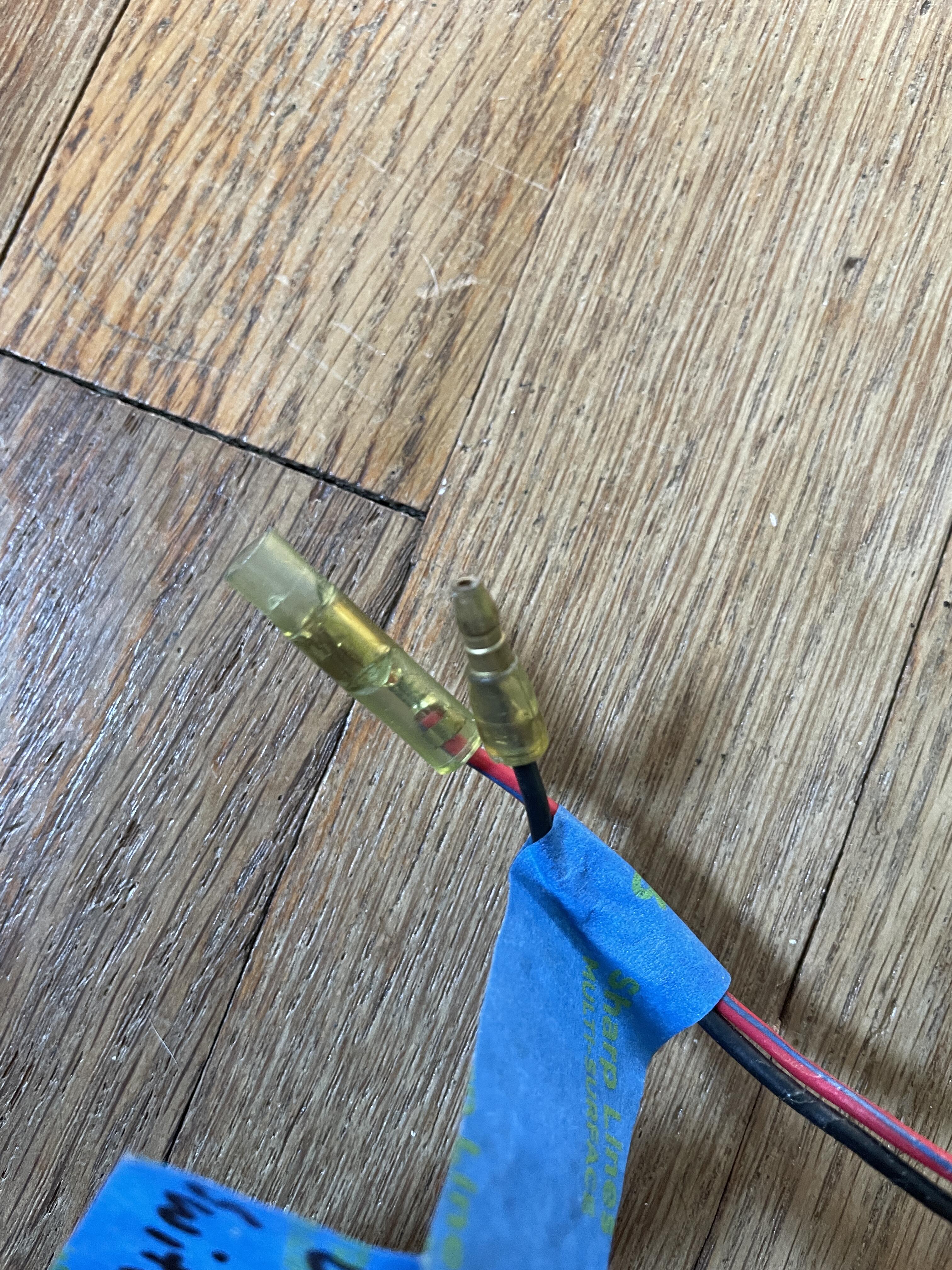
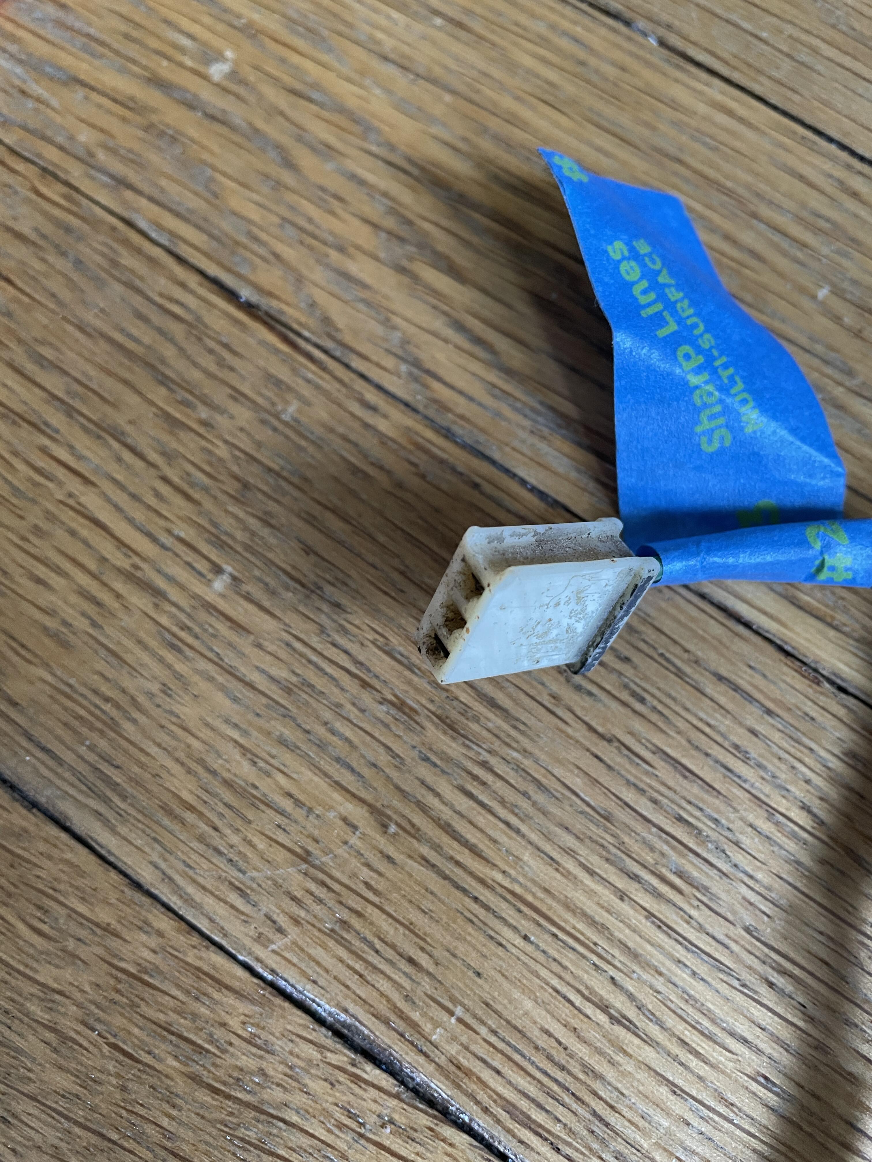
I have verified that is is the right harness for my car by the part number printed on the white shrink near the blue clip (24014-n3300). It isn't the one that came with the car, which I can tell because it has metallic green overspray on it and I am pretty sure my car never had. I think it is for a 7/72 to 7/73 car, which mine is (7/73), but it has the black connector sleeves for the defroster, which came on the 75-83 harnesses according to Banzai Motorworks. I still have two things I have not been able to figure out about this harness, though: 1. This one is minor. The room light wires should be Red w/ Blue, Black, and Black. I have 3 long wires that I know are for the room light based on the connectors on the ends, but they are Red w/ Blue, Black, and Red w/ Black. Is this maybe just a foible of my harness? I know these aren't mixed up with the defroster wires because I have accounted for those and verified them by the connectors on those wires, even though they are the same colors. This would not be the only place where the wire colors deviate from the diagram. The rear combination light connectors don't match the diagram either, but they do match the FSM. 2. This one is perplexing. I have two wires (White & White w/ Black stripe) coming out of the harness at the same point as the two wires that go to the left rear marker light. I haven't been able to find these in any of the wiring diagrams for any year. As far as I can tell, these do not go to the tail lights, license plate lights, fuel pump or sensor, antenna, or marker lights. Is this maybe a European, Canadian, Californian, or Right-Hand-Drive harness? Some of the diagrams specify market-specific options and others are USA only. They do have the same connectors as the Step Light wires on the other end of the harness, but that runs into the door from the front on the right side. The left door switch is on the dash harness, plus the connectors don't match, so it isn't that. Maybe rear fog lights (not in the diagram)? I'm pretty sure that these supply signal and power to the speaker that was in the left rear quarter panel. Any help figuring this out would be much appreciated!

-
Okay, my plans suffered their first casualty: I will not be going with an electric compressor on my AC system. It’s possible, but I would need to have a 200 amp alternator to handle the draw. The one I have is 100 and can’t cover it. I would also have to figure out some kind of controller to make sure it was operating and cycling correctly, and I’m trying to avoid computers. The thing that really tipped it over the edge, though, is having to move it out of the engine bay to keep it cool. These things are too big and need pipes to the condenser, even if you move the condenser somewhere too, so there isn’t an obvious place to put it. So that simplifies my project a little. I can probably pull the trigger on my AC parts now. —- I think I want to have my additional interior components on a new / additional harness. I haven’t decided if it would attach to the body harness or the dash harness yet, but it is for my additional power supplies to charge phones and a Bluetooth speaker. At least two of them will be USB-C plugs, and the last either a 12-volt plug or another USB-C.
-
I just learned something that is not immediately obvious to someone who has never done this kind of thing before: The positions and lengths of the lines in the wiring diagram DO NOT correspond to my harness very closely at all. Yes, the wires connecting one component to another are captured in the diagram, but there is no relationship between either the length or the proximity of one wire to another in that diagram to what is in the car. What I mean by this is the just because two wires are next to each other in the diagram does not mean they are in a same harness. The best example of this are the blue/white and blue/red wires that go from the antenna switch to the antenna. In the diagram these are very short and not near anything else. These two wires are the longest wires in my body harness, where they are twisted up with 18 other wires. There is also a random blue wire in the 1973 diagram coming from the Accessory Relay and going to nothing. It goes between the two flashers in the dash and just stops in the empty space. Just a word of caution to anyone else jumping into their first wiring project with both feet. They’re great for checking wire colors but you need a physical representation to refer to in order to make a new harness.
-
Okay, the body harness has been stripped. I am very glad I didn’t try to use this thing. It’s melted / burnt in two places and has been messed with and rewrapped in three places. The next step is to compare this to the diagram and see what the story is.