inline6
 Subscriber
-
Joined
-
Last visited
Everything posted by inline6
-
 Thanks for this info. I was thinking to jam pack the thing. However, I saw the factory manual picture which indicated only a few areas to grease. I am having a hard time believing that, comparatively, a small amount of grease packed onto the bearing is sufficient for 4 or more trips around the globe, mileage-wise (25,000 miles around at the equator). So basically, the amount of grease I already have on the bearings and the seal... plus a little in the cavity to keep it from surface rusting is the way to go?
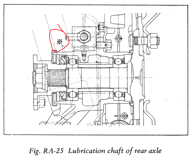
-
Thanks for the math. I suspected that at the installed spec, they may have very similar installed loads. I am guessing a production run change occurred. As to why, perhaps the shorter spring with thicker wire is more durable - less likely to fatigue?
-
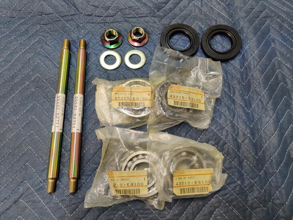
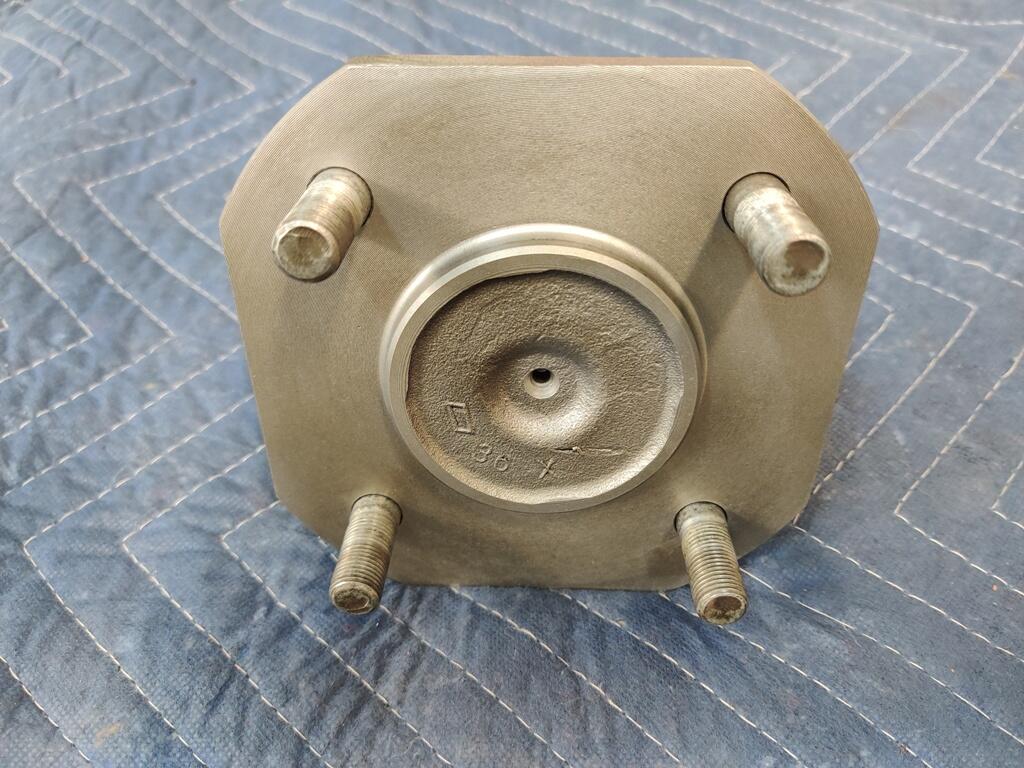
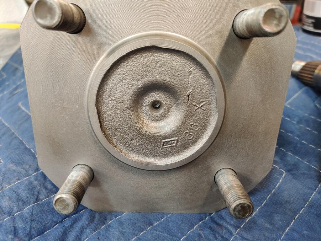
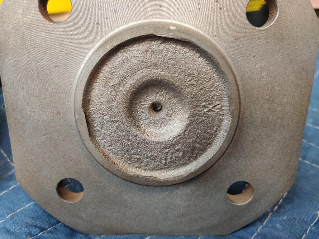
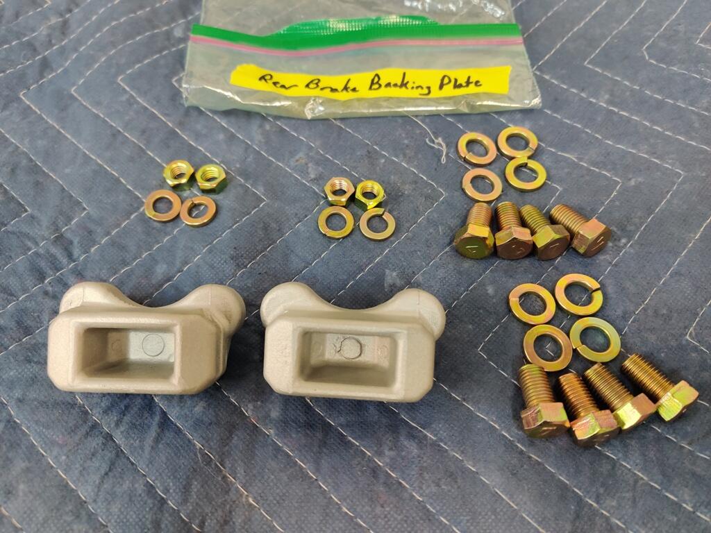
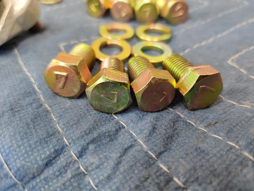
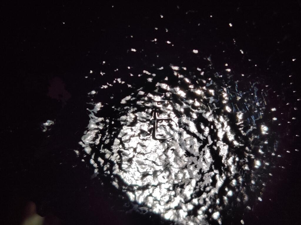
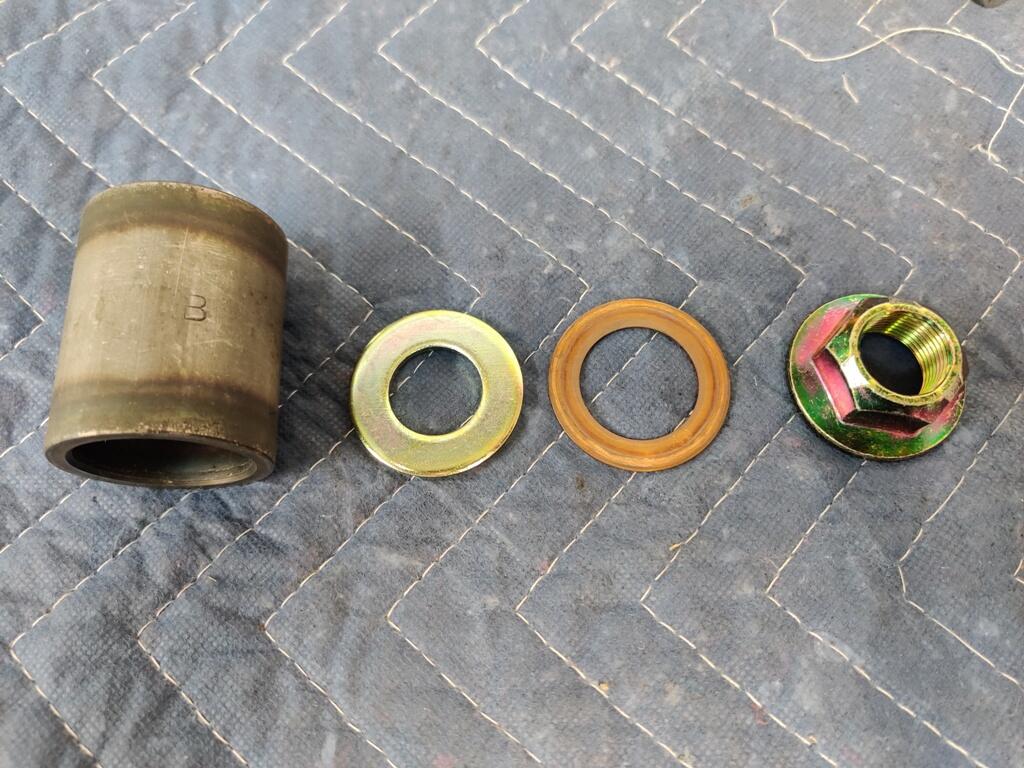
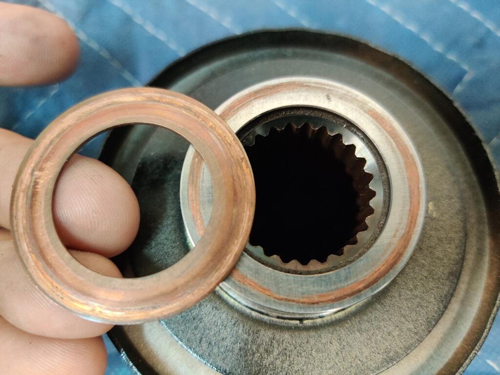
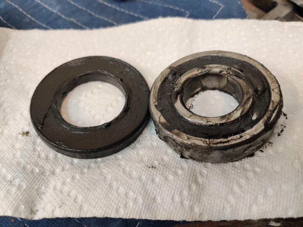
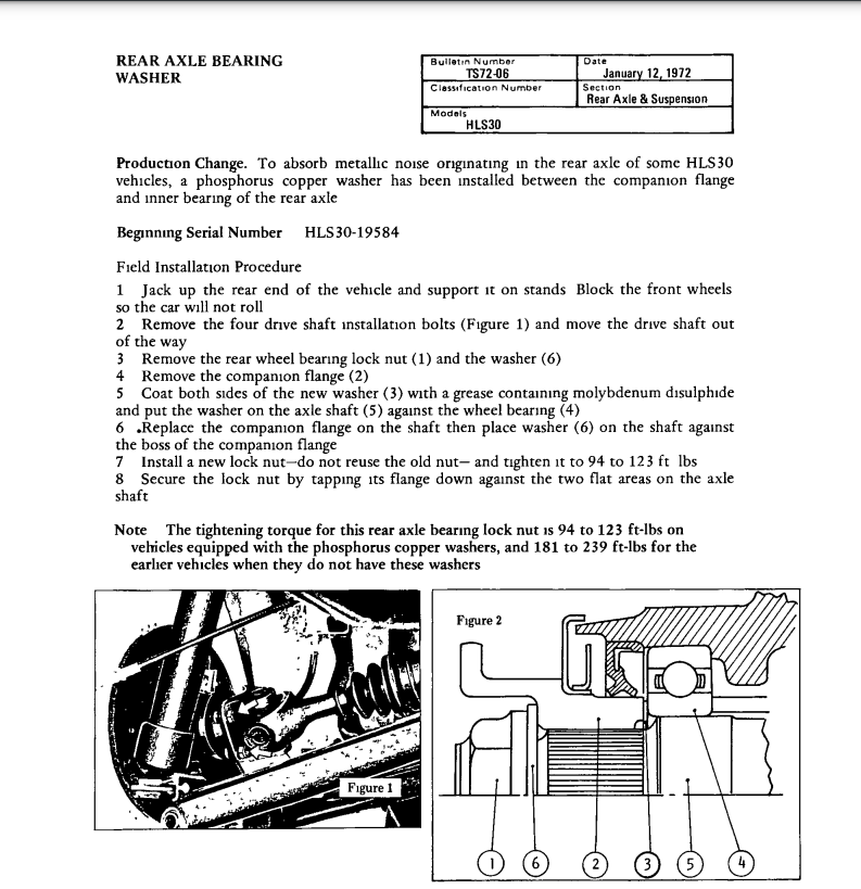
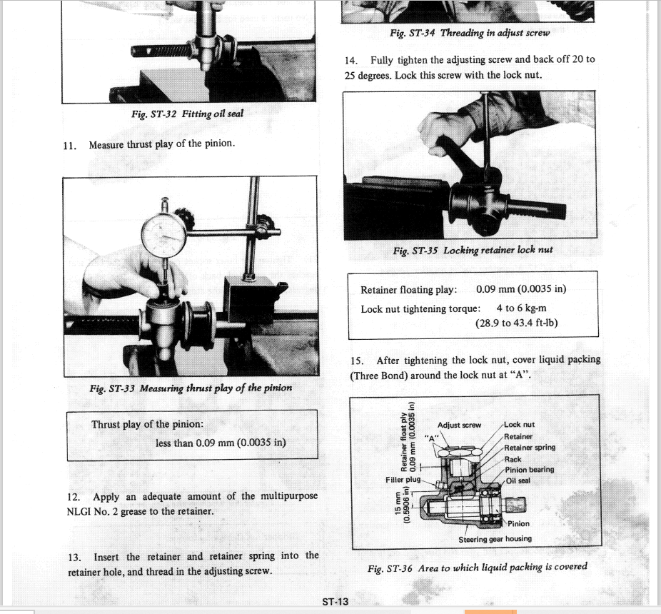
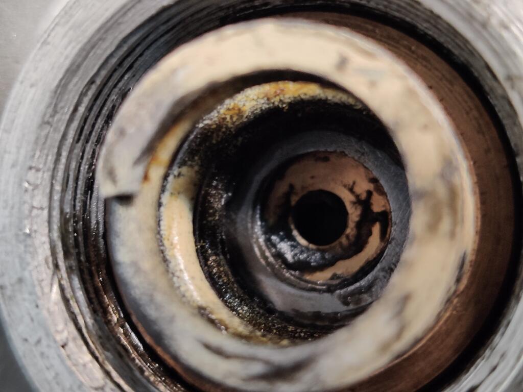
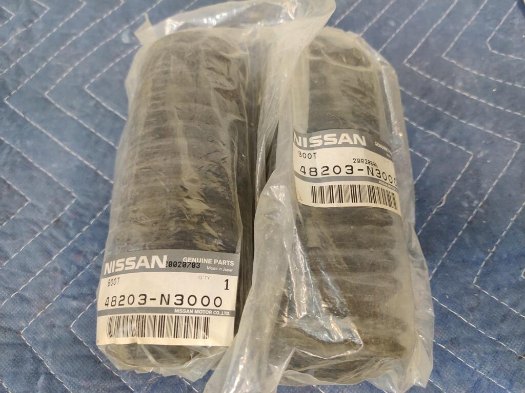
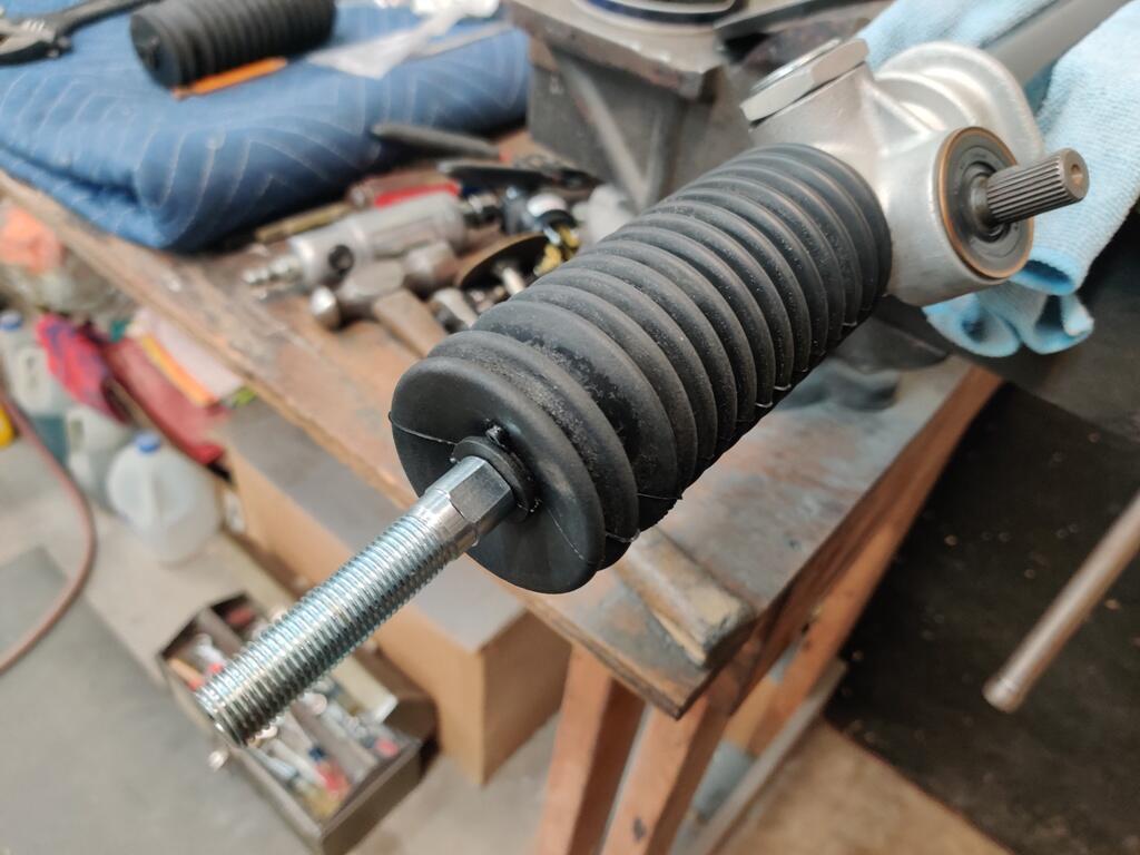
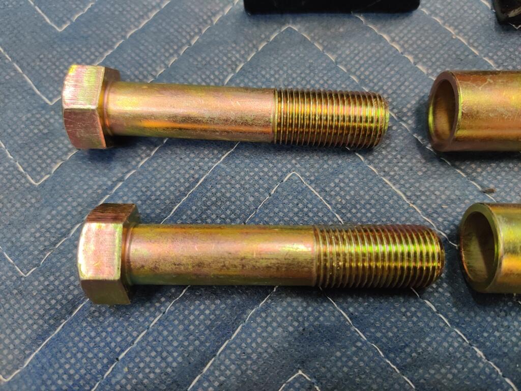
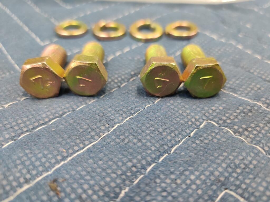
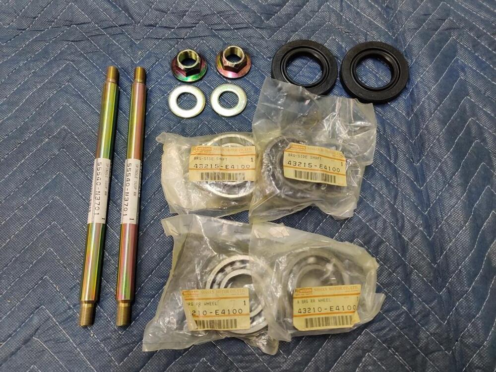
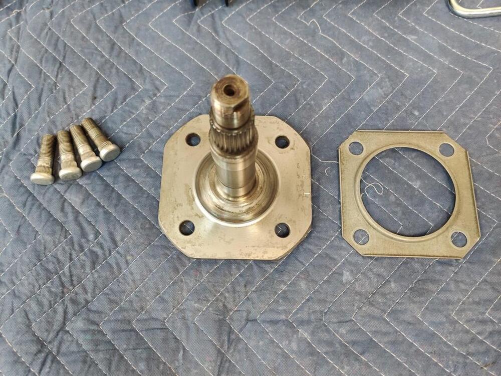
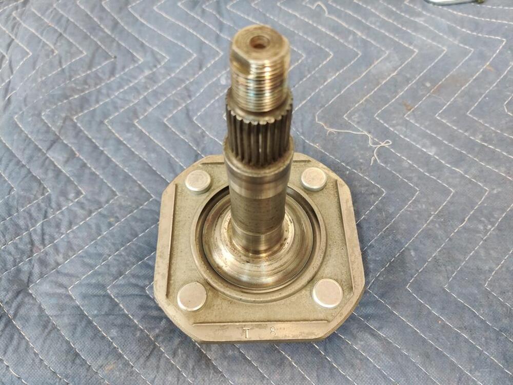
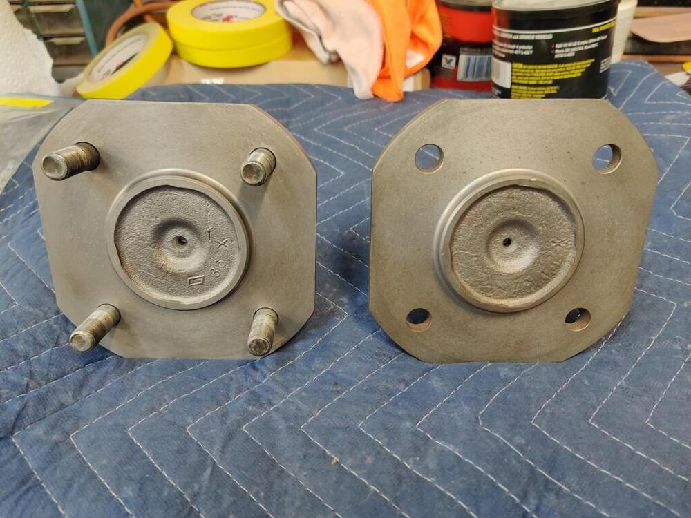
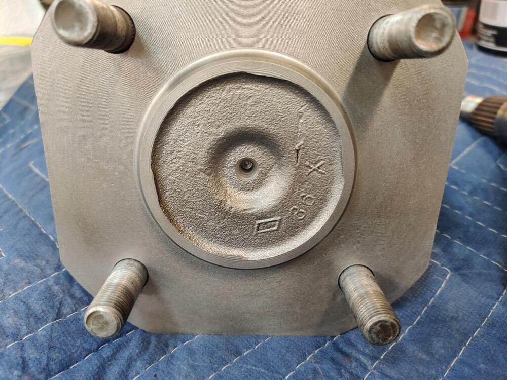
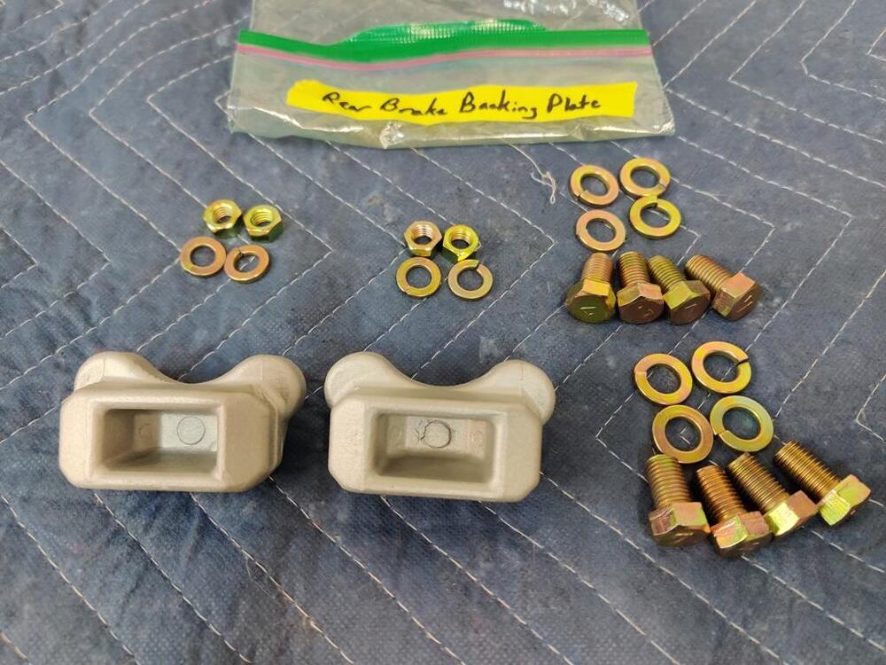
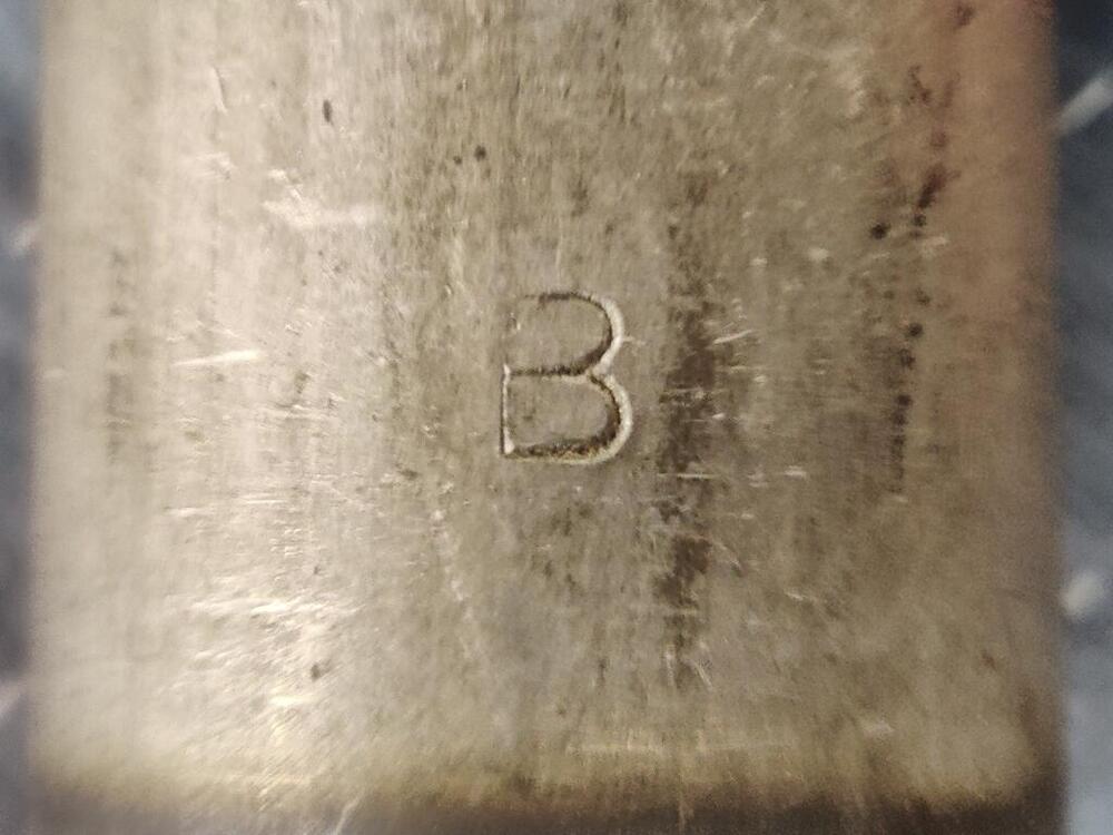
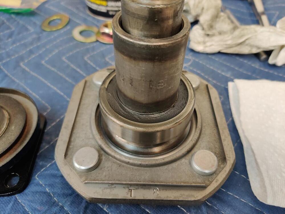
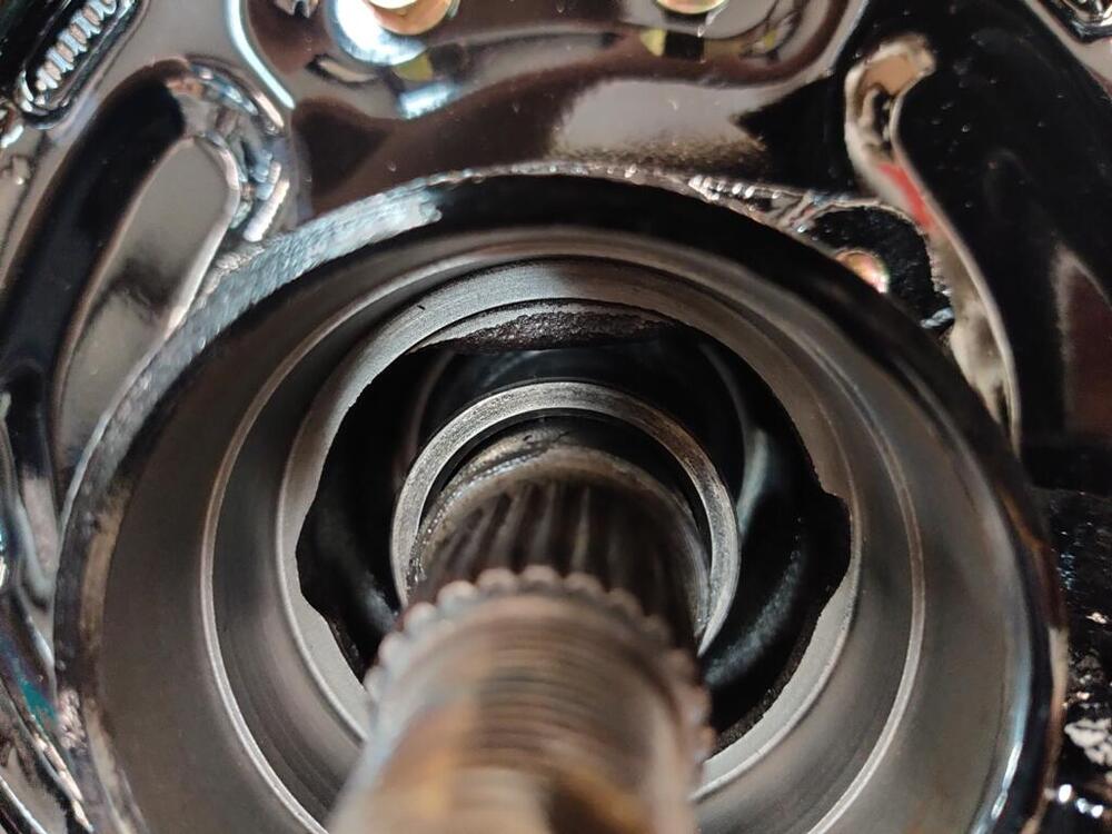
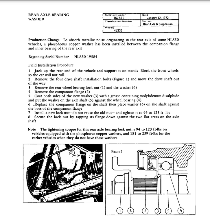
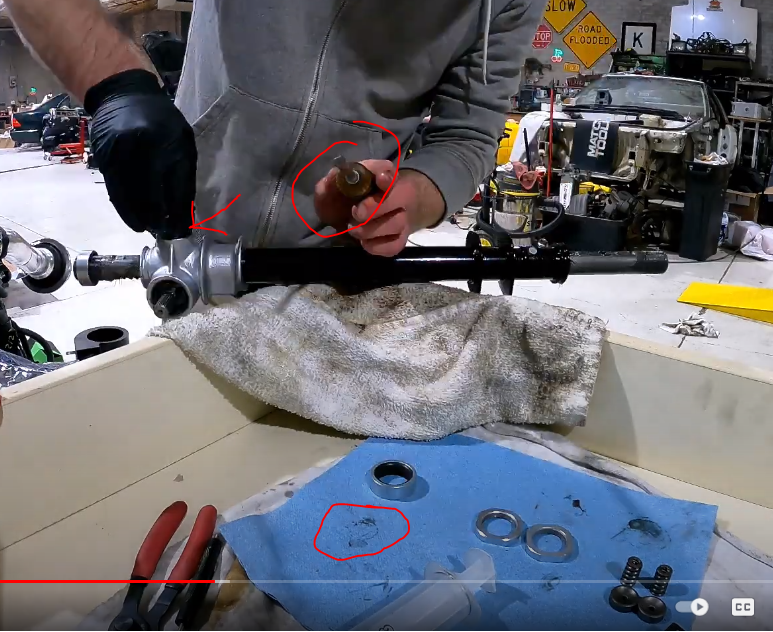
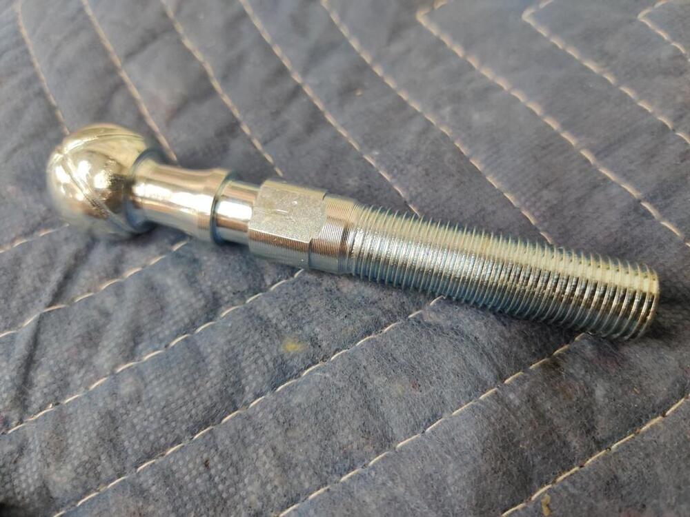
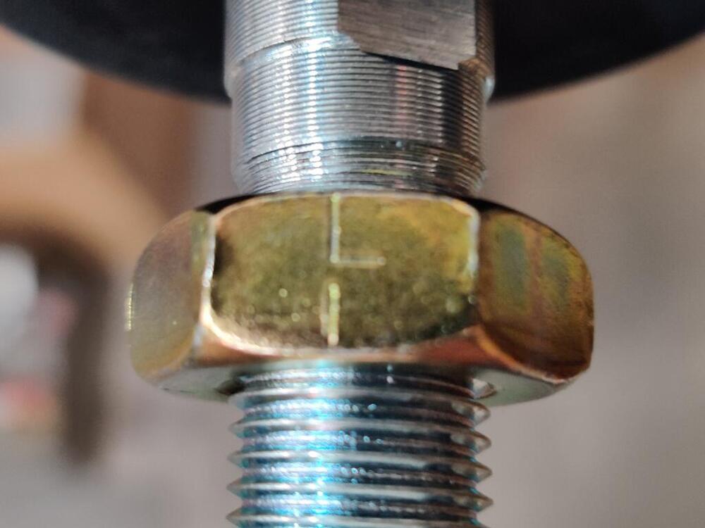
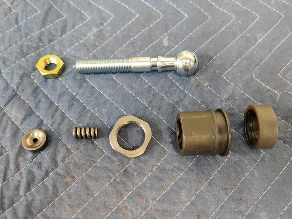
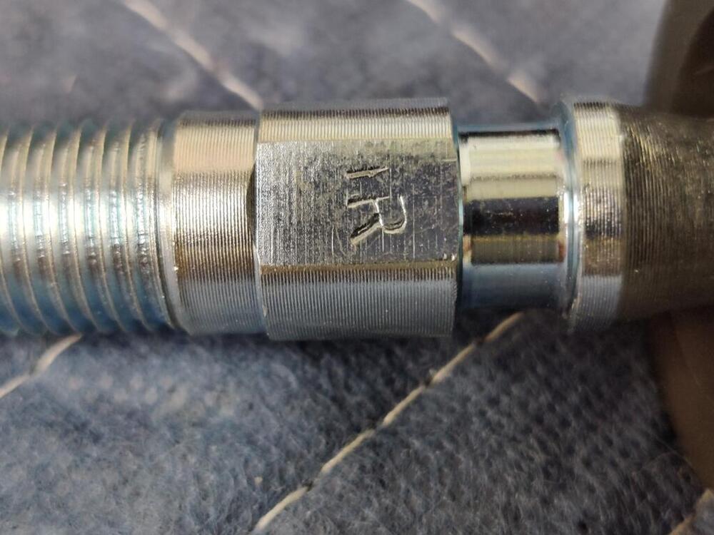
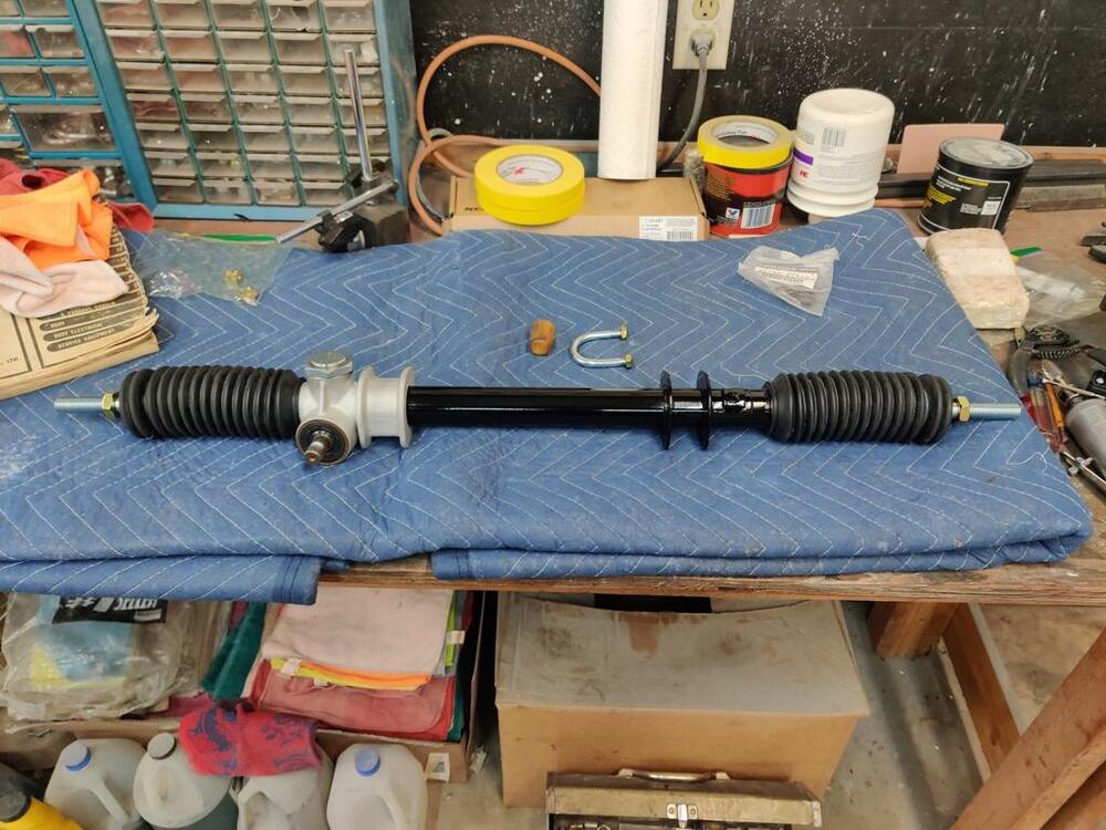
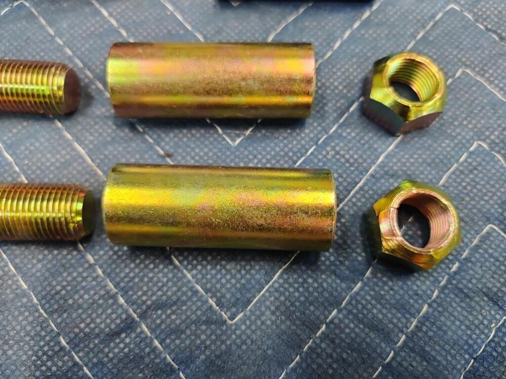
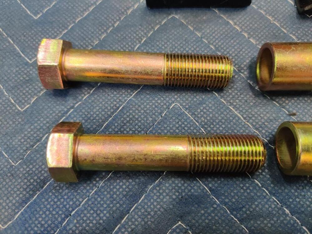
Tonight, I swapped the short spring in my rack out for the longer one that matches the factory manual. I also put one thin shim between the bronze bushing and the spring, and then, the thick and thin shims, in that order, and then the retainer. The factory manual specifies that you tighten the retainer screw "until it stops". What makes it stop is that it bottoms out on the retainer (bronze piece). Then, you back off the retainer screw 20-25 degrees. I shifted the rack fully to one side, and then set the retainer screw per the factory manual. Doing this, I feel, sets the spec for the rack in a "low wear" zone. I think this would be closest to what the rack was like when it was new. My rack doesn't have much wear that I could see, but when you are talking about "retainer floating play" (clearance between the retainer screw and the retainer) of .0035", I think it is best to set the distance the way I did for a used rack. I also replaced the coolant in the rear struts with 10W30 oil. And I started to install one of the rear wheel hub/axles. From the factory, axles were not painted. They were installed in a freshly machined state. I decided to glass bead mine and then put a light clear coat on them to provide some rust resistance. I clear coated only one of the axles several weeks ago after both were glass bead blasted. With that time sitting in my garage, the non-clear coated one started rusting noticeably - the clear coated one has studs installed: New parts and the hardware for the brake shoe backing plates: Starting axle installation "B" on spacer and on strut housing: I believe this washer I am holding is the phosphorous copper washer mentioned in the TSB below. It is pretty clear from the transfer of material to the axle flange where it was located. Note that the torque setting on the rear axle bearing lock nut is far lower - only 93 to 124 ft-lbs vs. 181-239 for VINs HLS30-19584 and prior. I am at the point of the axle installation where I need to add more grease. I have filled the inside of the outer rear bearing, both sides of the inner bearing, and the inner oil seal. Look right? Thoughts on how much grease to put in the axle housing? Do I fill the whole strut housing cavity, attempting to eliminate any air pockets?


-
Yes, the shorter spring has a wire thickness of .116". It may be possible that at the same installed height inside the rack, each spring is close to the same pressure/load.
-
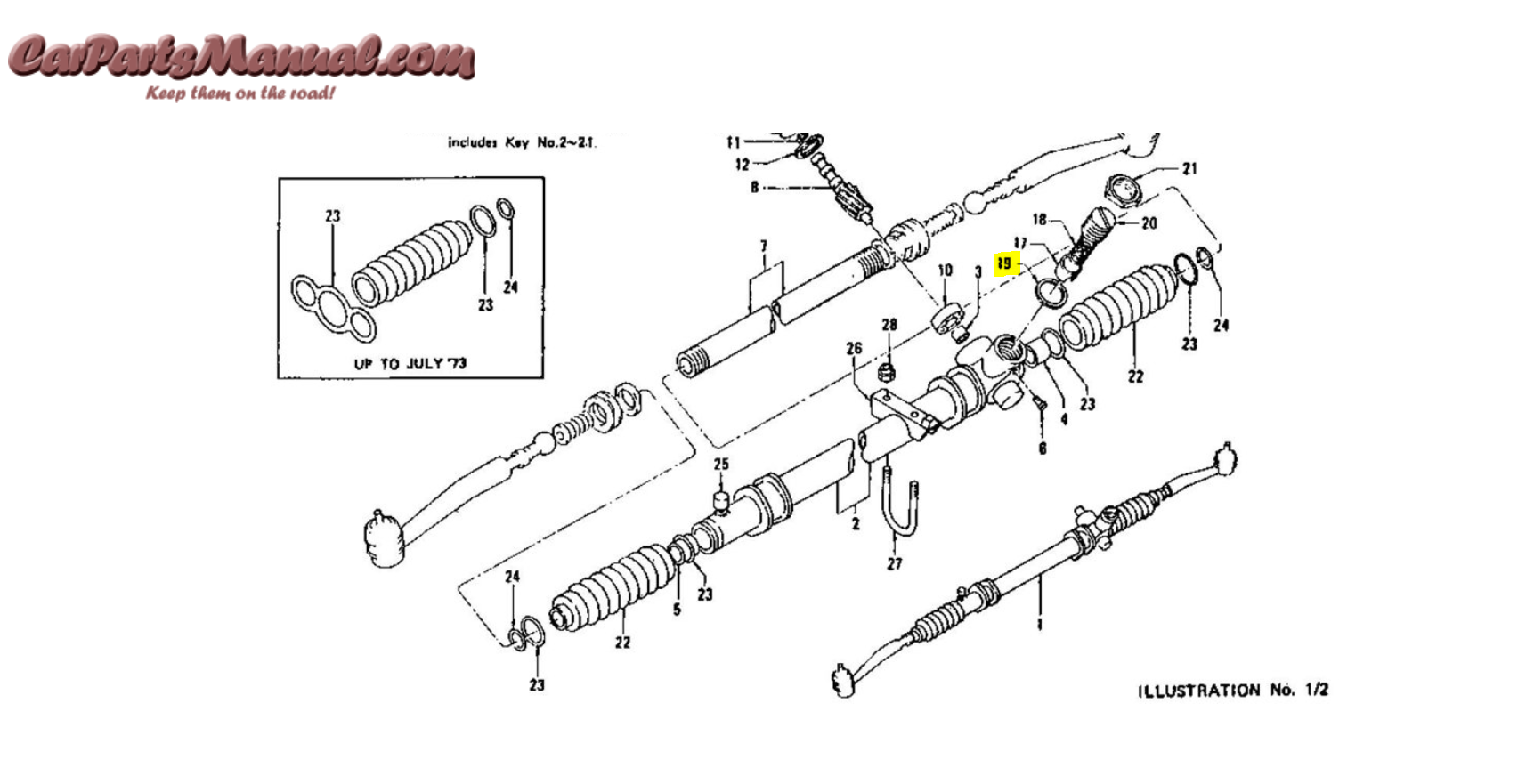
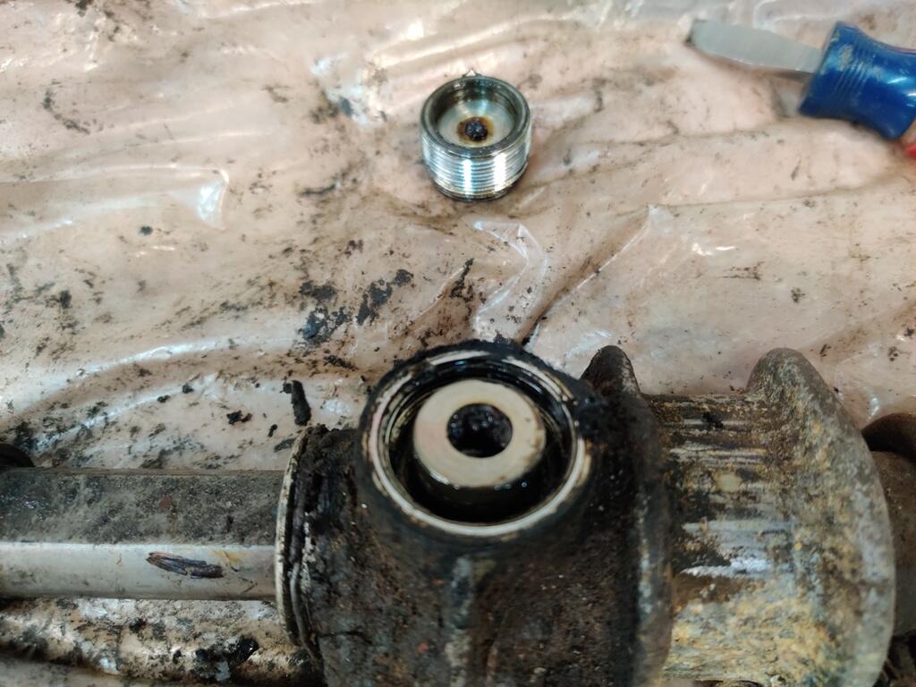
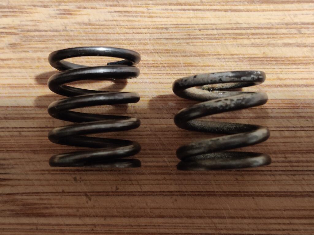
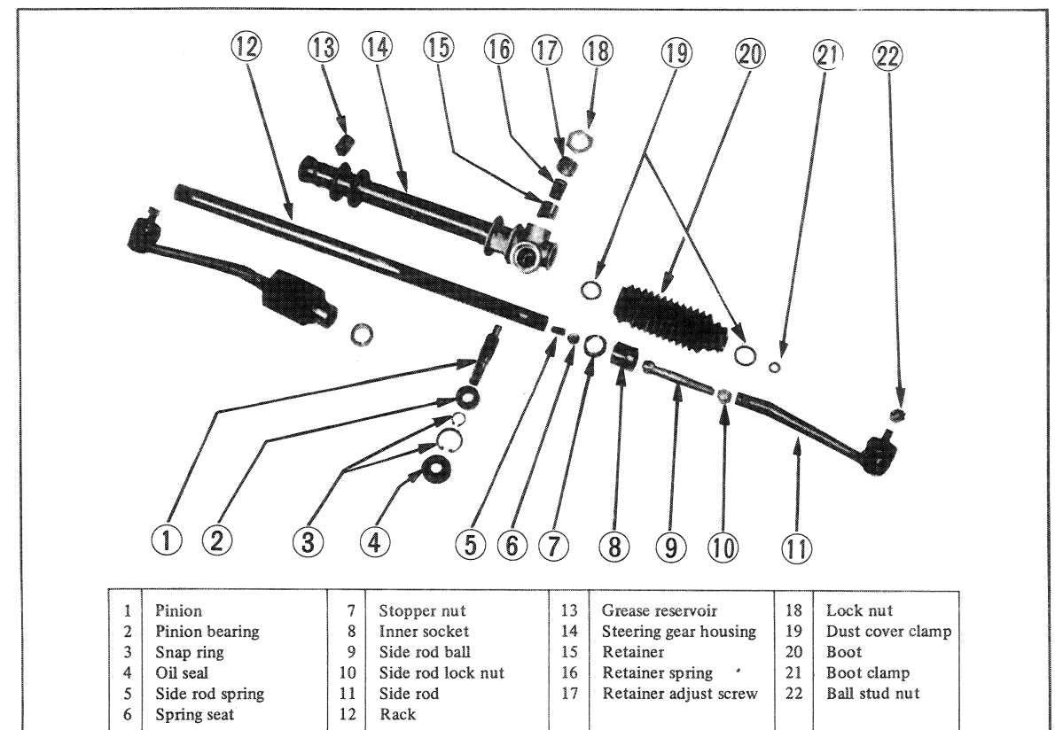
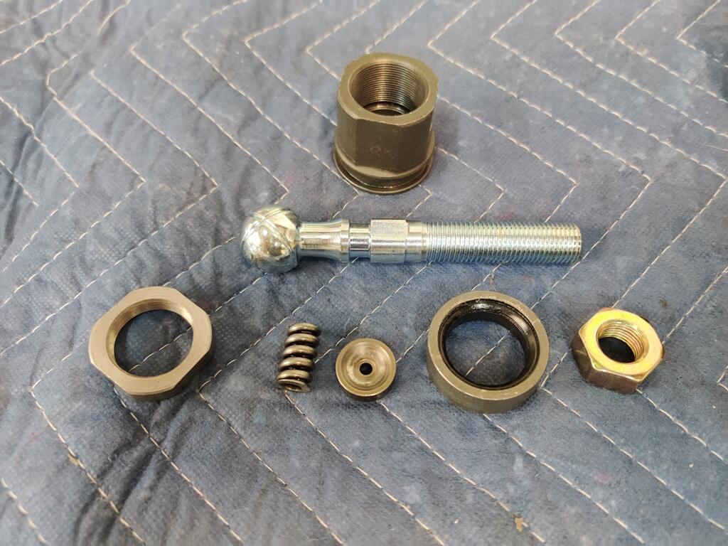
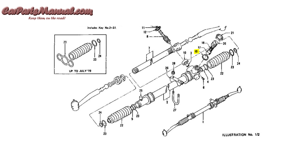
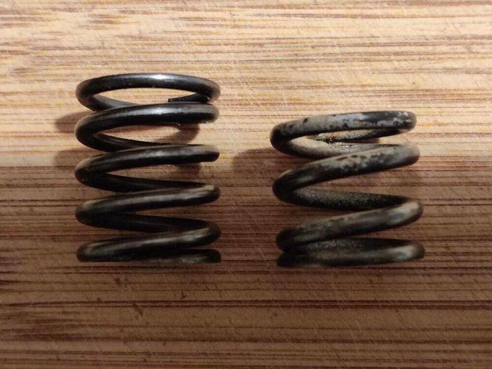
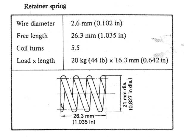
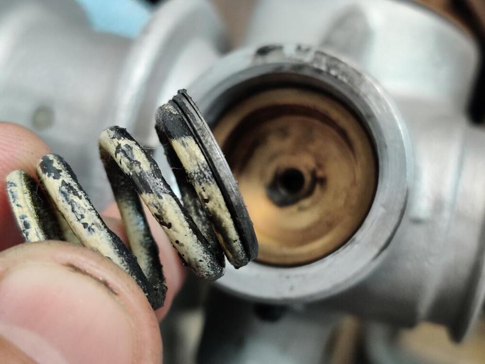
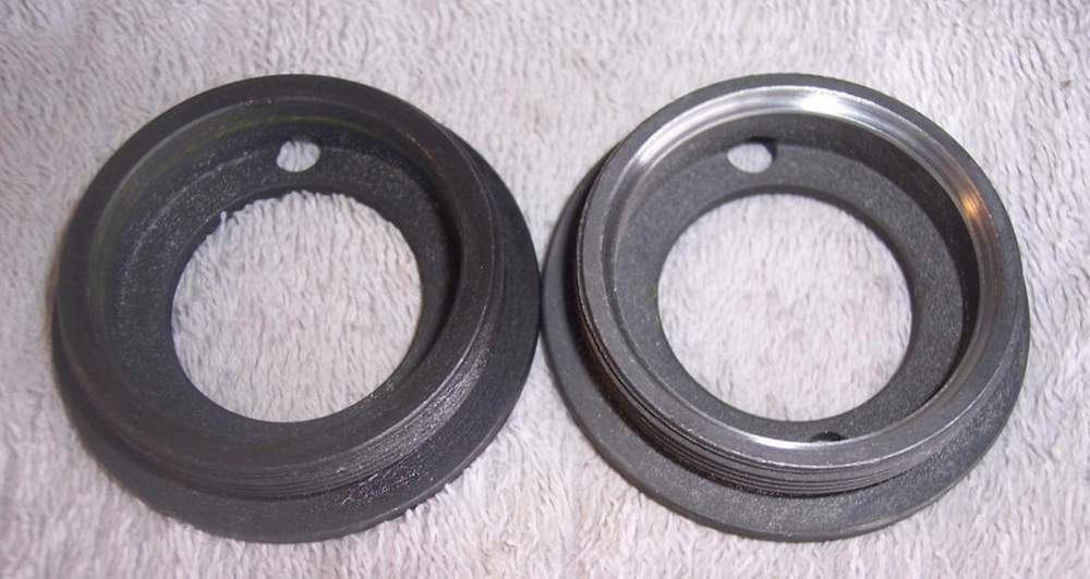
There are part numbers for shims shown in the parts book, but the location in the drawing is inaccurate - they do not go below or around the bronze bushing: I see that the retainer spring in the rack I reassembled yesterday has a spring just like the one I removed from the rack today - not quite four coils. Interestingly, I do have one of the springs that matches the retainer spring specification from the factory workshop manual. I may have ordered that spring from Nissan around 1994 when I rebuilt the rack on my original 240z. At that time, I was able to source new bronze rack bushings, new pinion bushing, new bronze retainer, a new pinion gear and pinion gear bearing. I think it likely that I ordered a new retainer spring while I was replacing all of those parts. I had a slight shimmy in that car for years even after rebuilding the rack, and it wore the rack considerably at dead center. Only later did I found out that the ball joints (appeared to be new, so I looked at other things first) were the cause. Because that rack was worn, I swapped it for another, which is still in that car. Salvage car rack - as retainer was removed - thin shim against retainer, thick shim against spring: Spring on the right is from the salvage rack - looks to be the same spring spec (even white paint on it) as the retainer spring in the rack I assembled yesterday. Spring on the left matches the specification from the workshop manual for the retainer spring. Coil diameter measures right at .102" . Free length was 1.015" instead of 1.035". But it has been compressed in a rack for about 30 years, so maybe that is why the free length is a little short. These springs have very different lengths and loads. I wonder what the deal is - why these differ so much from the specification in the workshop manual.

-
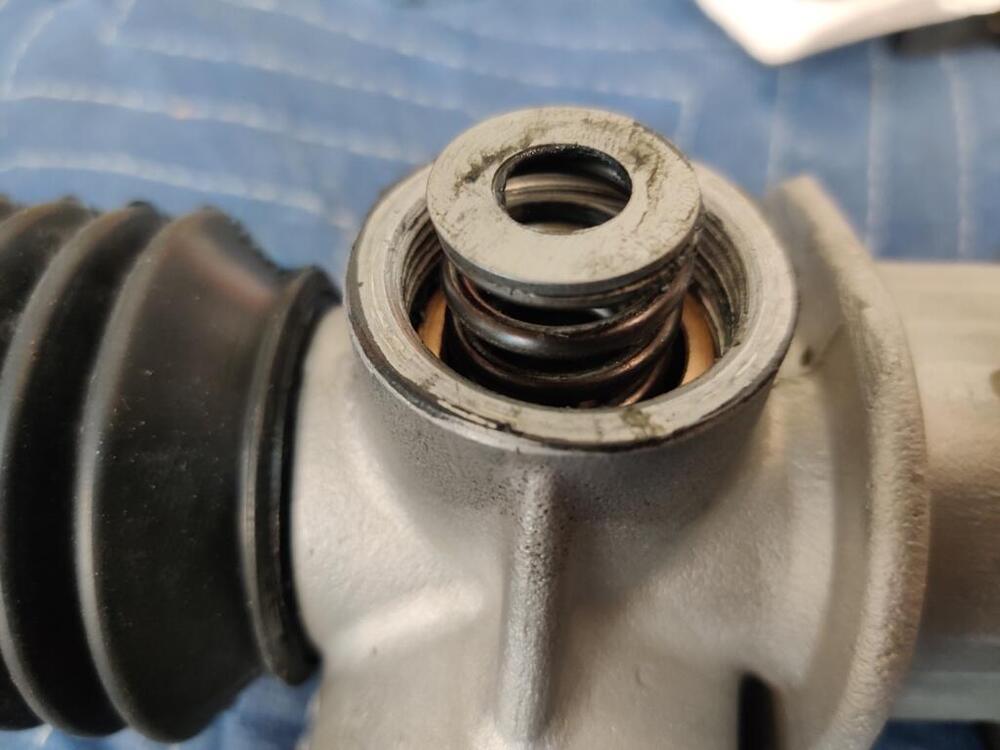
Many years ago, I grabbed 240z steering rack from a salvage car in a yard. My thinking at the time was that I could send it in as a core on rebuild exchange some day. Tonight, I removed the retainer nut and screw, and found two washers - one thin and one thick sitting on top of the spring. There was no shim under the spring - the spring was sitting on the bronze retainer. Since the rack has been in my possession since the 90's and is covered in tons of gunk, I assume it has never been apart. Of the three youtube videos I can see, one puts the washer(s) under the spring against the bronze bushing, one puts the washer(s) on top of the spring, and one has no washers. There are no shims in the picture in the factory shop manual which identifies all of the parts to the rack (15, 16, 17): I suppose it is possible that the shims were used to adjust the amount of spring tension pushing the retainer against the rack... with the retainer screw in the precise installed position per the factory manual instructions. Steps 12-15 pertain to the retainer and retainer screw installation: Perhaps originally, they were added by factory worker in a fashion such that, the retainer screw was set per factory instructions, and then some type of resistance check was made. Then this was followed by adding shims (remove the retainer screw, add a shim, replace retainer screw, then check resistance again... Anyway, that is my guess. Another interesting thing I am just now seeing: the retainer spring I took out of my "undisturbed" rack does not match the specs for the 71 manual, which are here: Free length is about .890" and it is only composed of just under 4 coils. Odd!


-
I can confirm that the washers do not fit on the pinion gear/shaft. The factory workshop manual provides information about selection of different snap ring thicknesses to achieve pinion gear end play of no more than .003 something. In the Youtube video above, it is a little difficult to determine where that guy put the washers even slowing the video to .25 speed, but I see that he puts them (it looks like he has two) directly between the spring and the large retainer screw. These two freeze frames show, bronze shoe missing from parts on rag and spring is in the "well" - retainer screw in hand... Washer now missing from rag, retainer screw being threaded in, screwdriver in left hand. I have a spare rack, and will pull the retainer on that one to see what I find.

-
Today, my focus was on the steering rack. I was unable to find any pictures of the shims in this third picture, neither in my disassembly pictures, nor online. They aren't in the pictures in the factory shop manual either. It seems incorrect to me that the spring would push directly on the brass/bronze bushing, and there were no wear marks from the spring in that surface. There were two very thin washers and one thicker one. I stacked them - thin - thick - thin and put them between the spring and the bushing. Is that correct? Other than keeping the spring from eating into the bushing, I don't know why these would be needed. If there were just the two thin ones, I'd have put one on each end of the spring. Given that the larger retainer screw adjusts down against the spring, I see no reason for a spacer, or shim in this location.


-
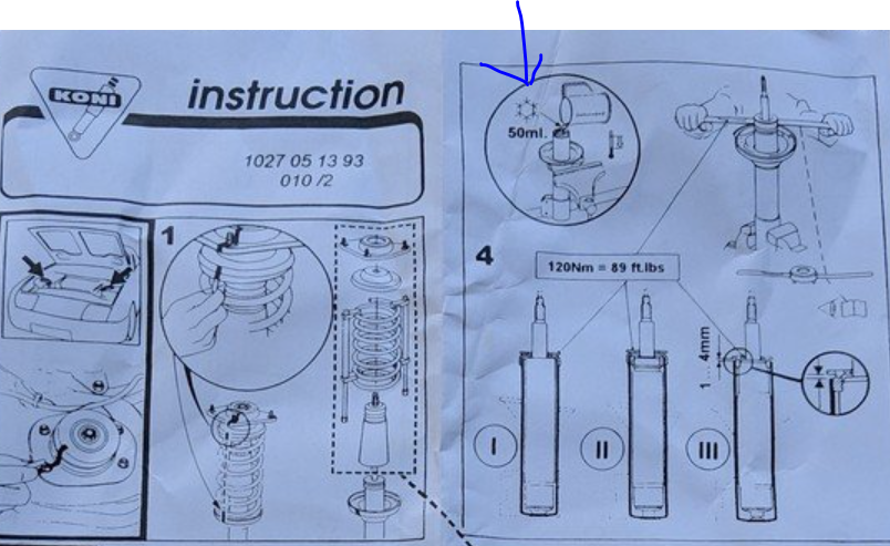
Ok, I will switch to oil. That is easily done at this stage. What types are typically used? The instructions show a picture... with a snowflake, and "50 ml" and a pitcher. Only thing that came to mind looking at the snow flake was anti-freeze. I assumed that heat transfer would be better with coolant, and that rust would not be an issue because of corrosion inhibitors in coolant.
-
I have not. Thanks for the suggestion. I will see what I can find out from places that are nearby.
-
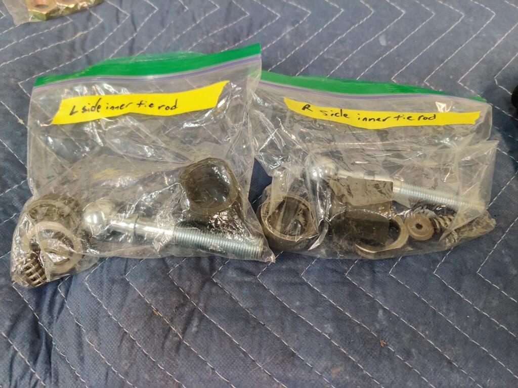
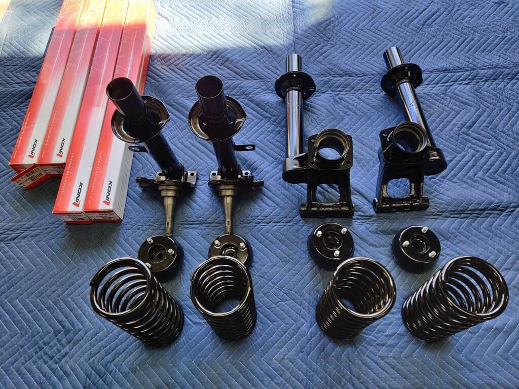
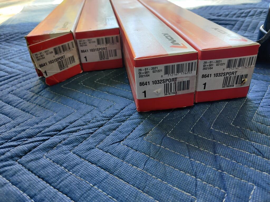
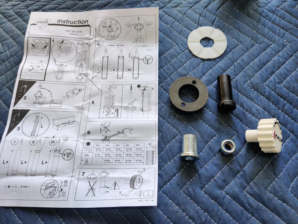
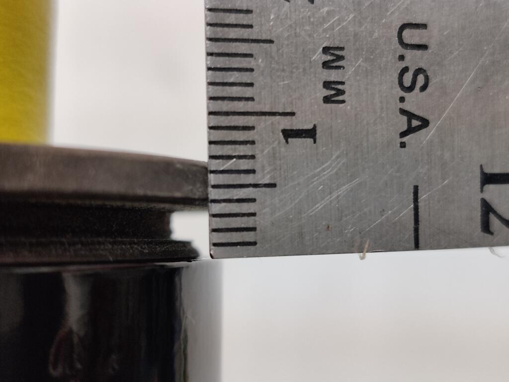
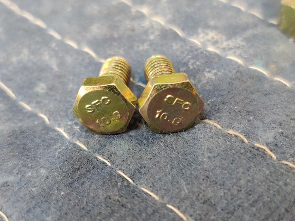
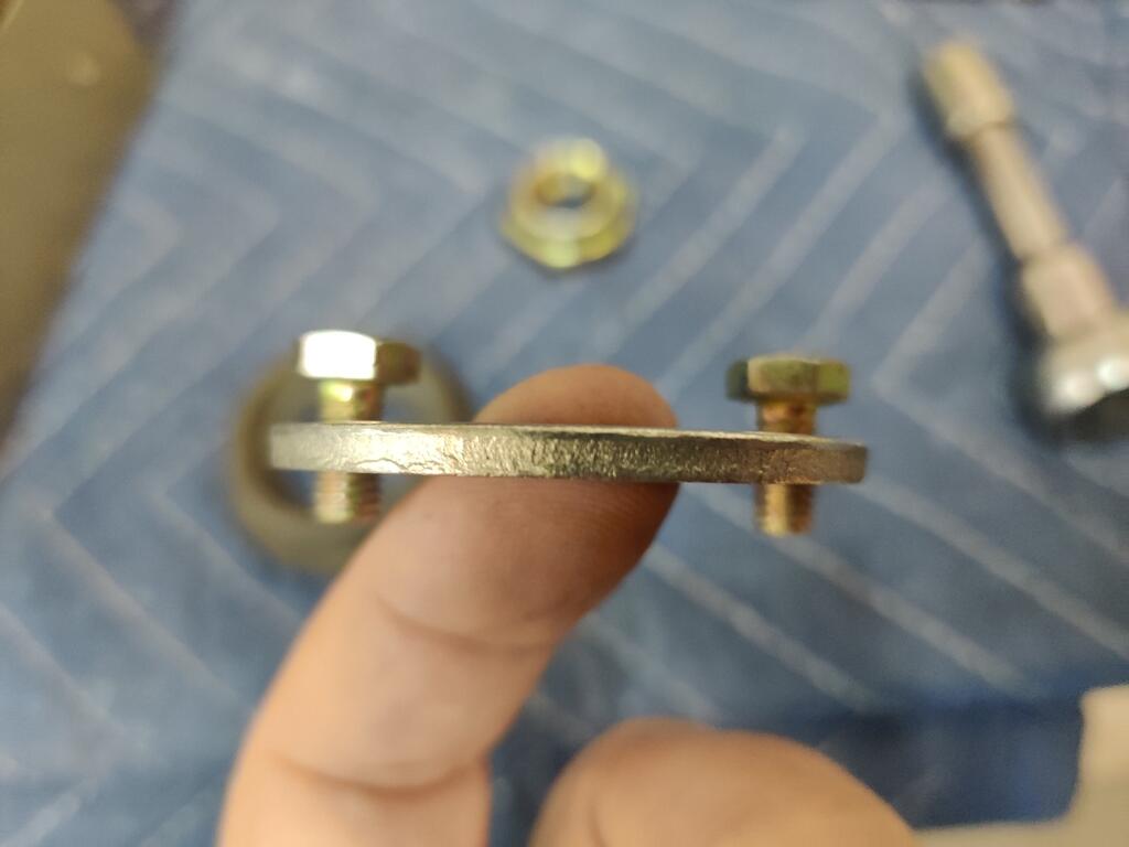
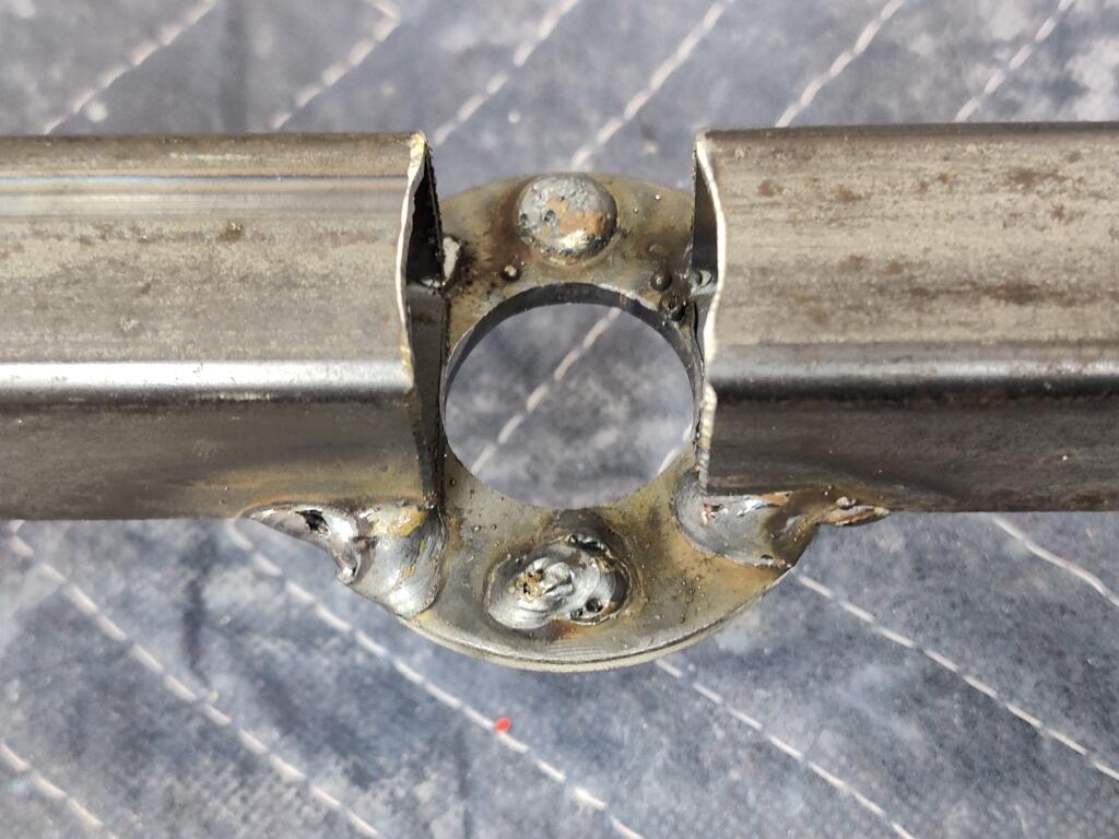
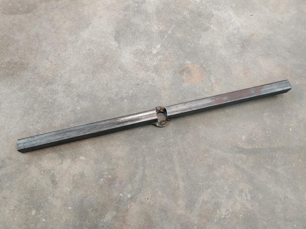
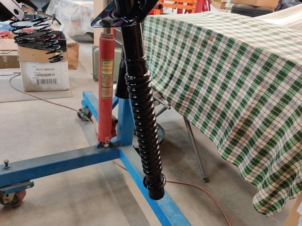
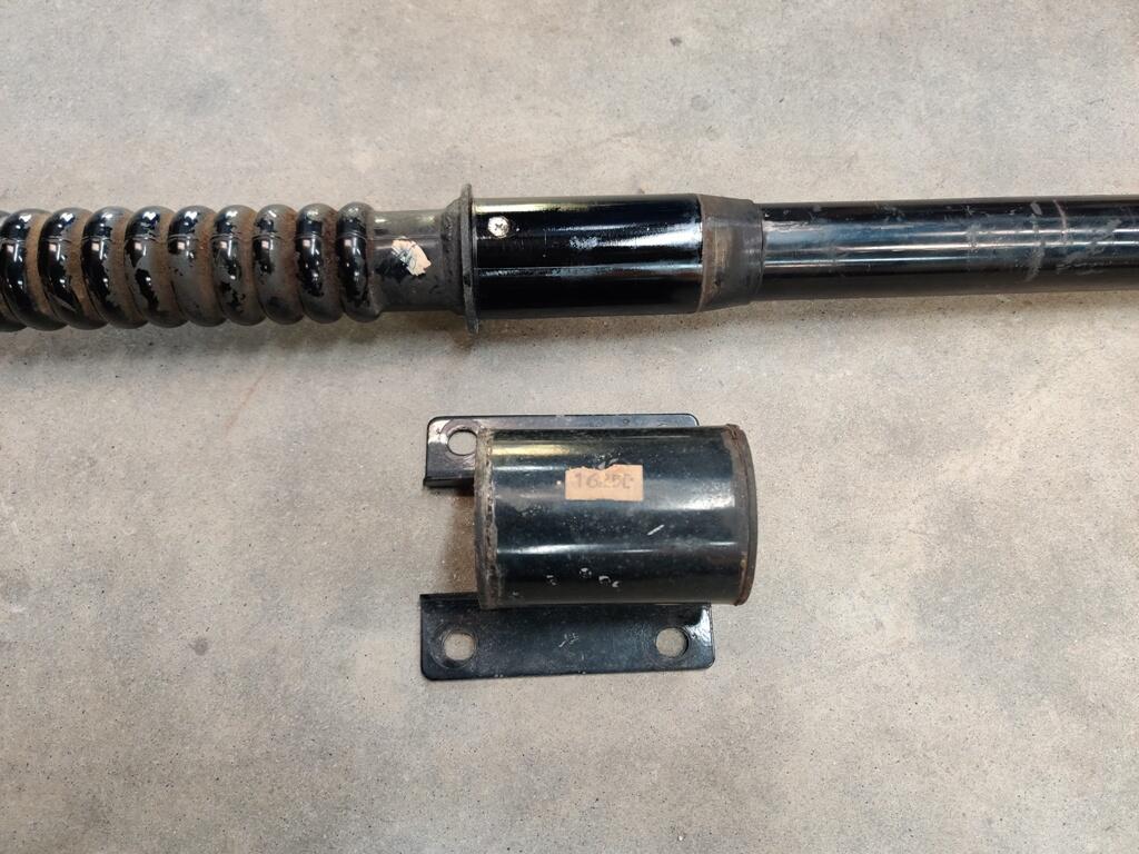
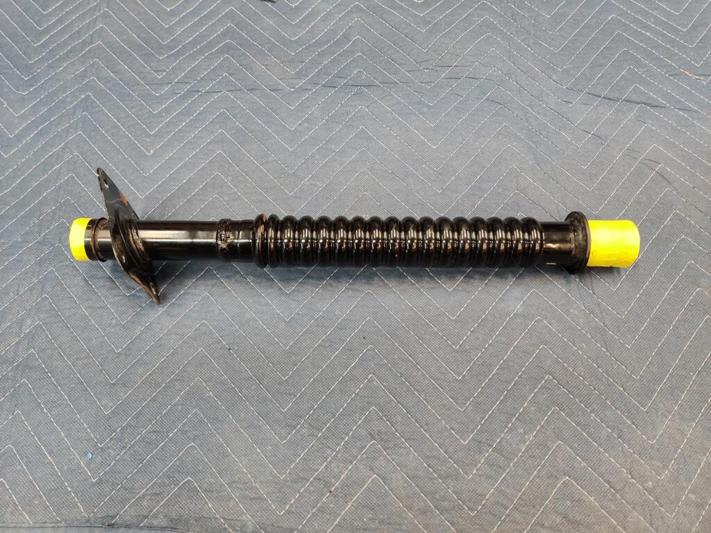
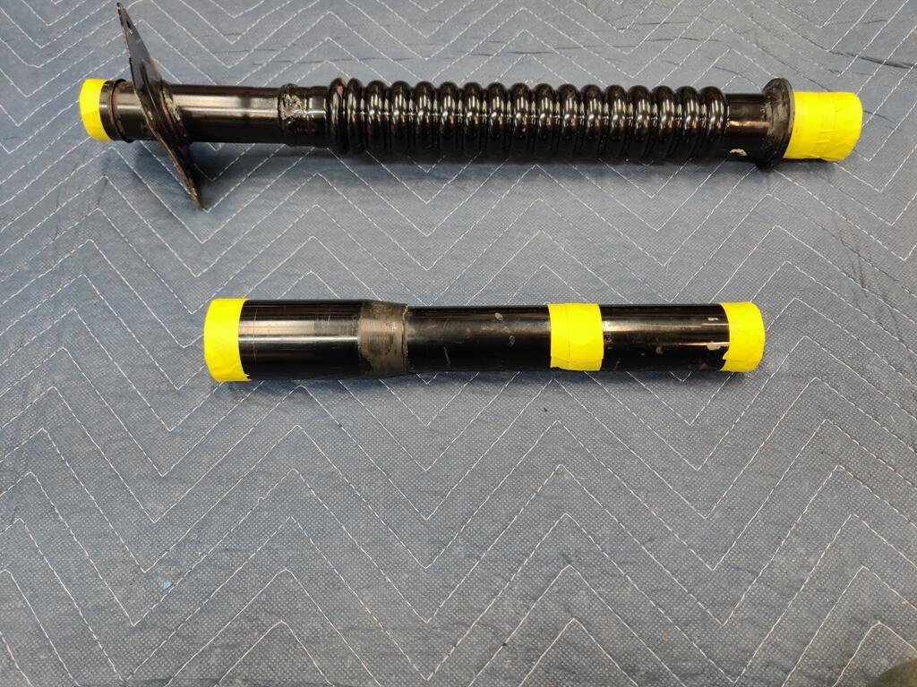
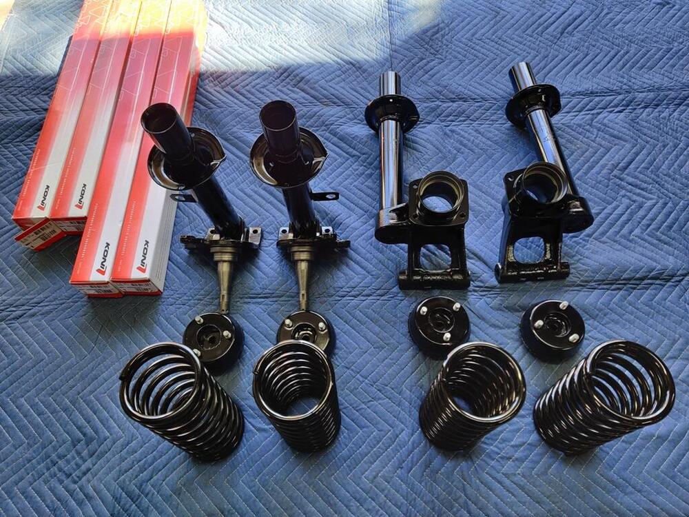
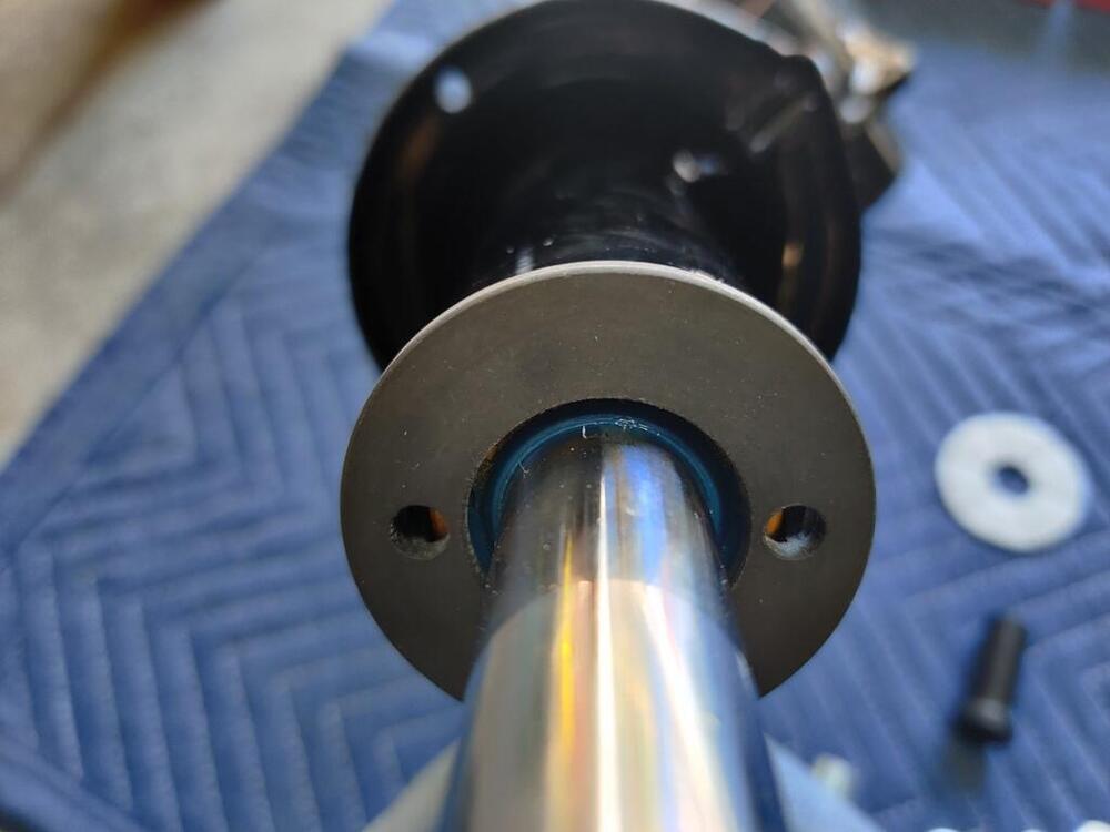
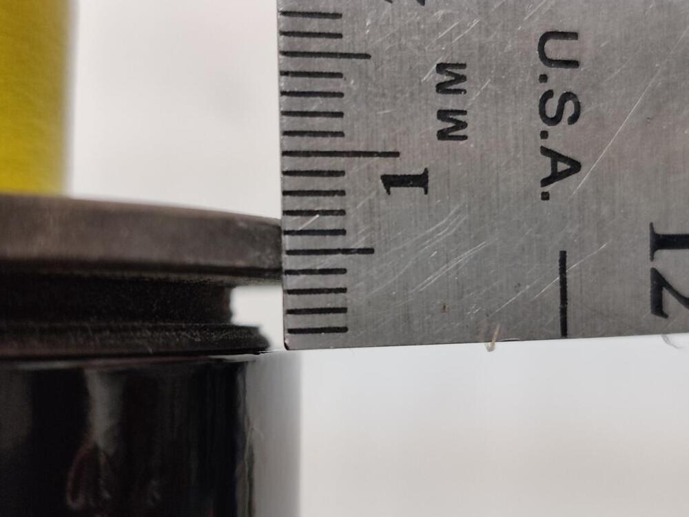
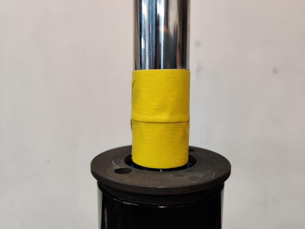
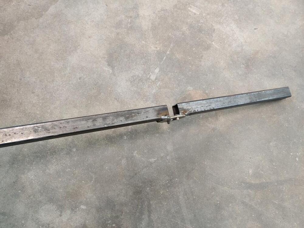
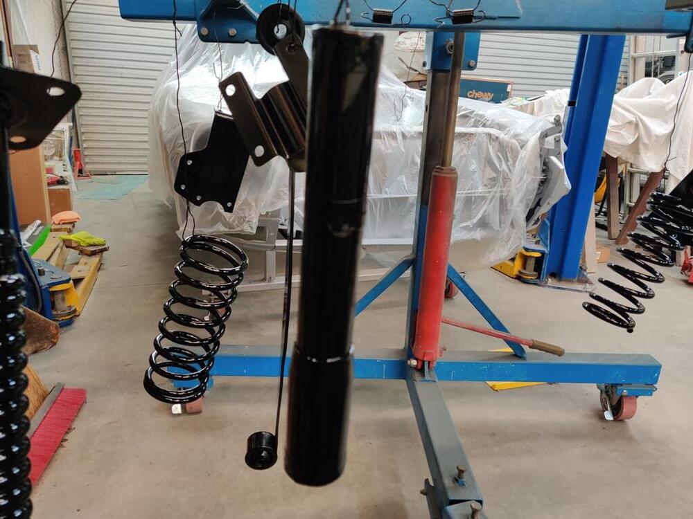
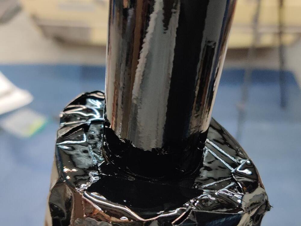
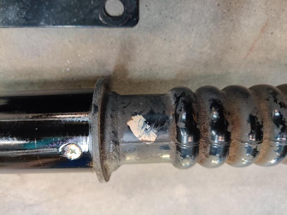
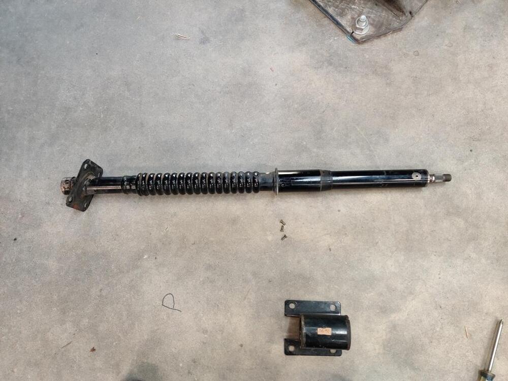
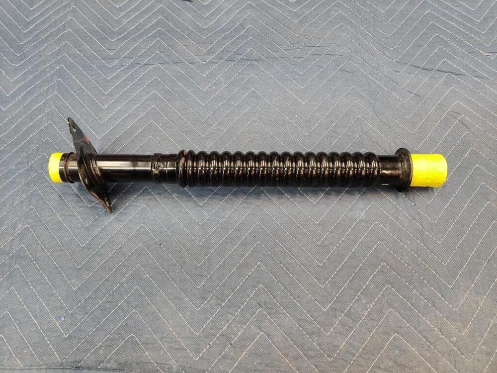
I ran into another issue with getting the engine and transmission in the car last week. None of the clutch throw out bearing collars in my possession were the one I need for this 240z clutch kit. So, I ordered a new one and I am waiting for that to arrive. So, yesterday, I switched over to suspension assembly. I bought the new Yellow Koni's for this car (see the linked thread below). The instructions... do not have any words. Manufacturers save on writing and translating when they do this, but I don't like it. It is not clear to me, in some pictures, what they are communicating. I was surprised to see that the "gland" nuts supplied with the Koni's do not have flats on the sides - they only have two holes in them. I have never encountered gland nuts like this before. I wasn't considering this, and got stuck with having to spend a good bit of time making a tool to deal with these. Essentially, I had to take a thick washer, drill corresponding holes in it, run bolts through the holes, weld those in place and then attach 1 x 1 bar to opposite sides of the washer. I started with the rear struts. Each one calls for 50 ml of non-freezing liquid. I used a 50/50 mix of distilled water and antifreeze. I think this helps with heat transfer from the Koni insert to the outer strut tube. I used two layers of masking tape around the shaft as a precaution to keep from scratching the strut shaft with the tool. After installation of the gland nut, the distance between the top of the strut and bottom edge of gland nut were just under the 1-4 mm specification. Switching over to the front struts, I ran into the issue that others have in the following thread. The insides of my front struts are clean and show no signs of any rust. However the gland nuts would only engage for essentially one turn of thread engagement. In the links below, you can get more context if you wish. I have contacted Motorsport Auto by email and asked about receiving modified gland nuts to fix my issue, as they did for Jim Arnett - @jfa.series1: So, a spacer/shim I think will be needed to assemble the differential is on national backorder with no ETA. No progress can be made on the differential. I am waiting for a throw out bearing collar to arrive. No progress can be made with putting the engine and transmission in the car. I am waiting to see if Motorsport auto can send me modified gland nuts. No progress can be made with assembly of the front struts, but I can continue with the rear struts. Today, I will pivot to the steering rack. Perhaps I can make progress there, and with further assembly of the rear struts.


-
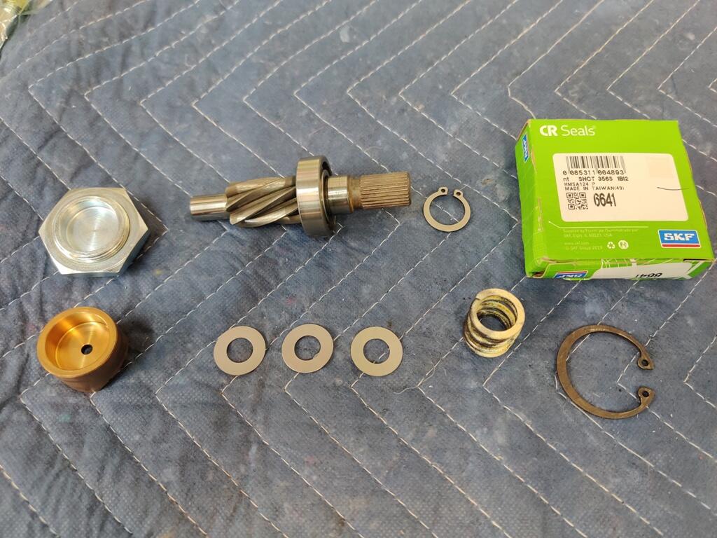
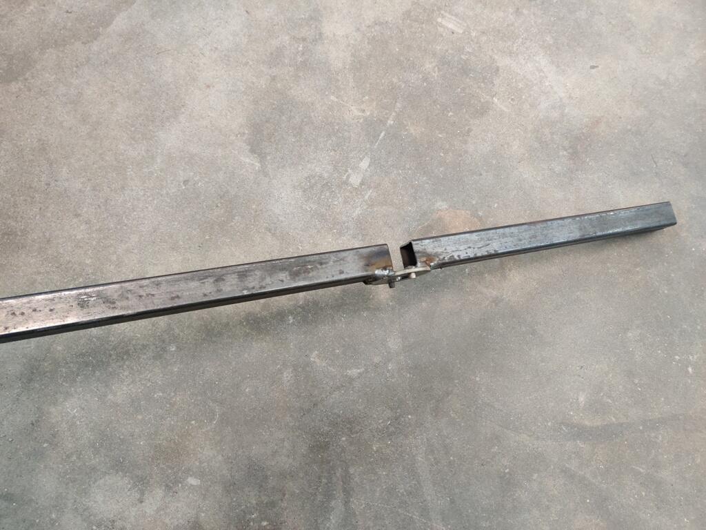
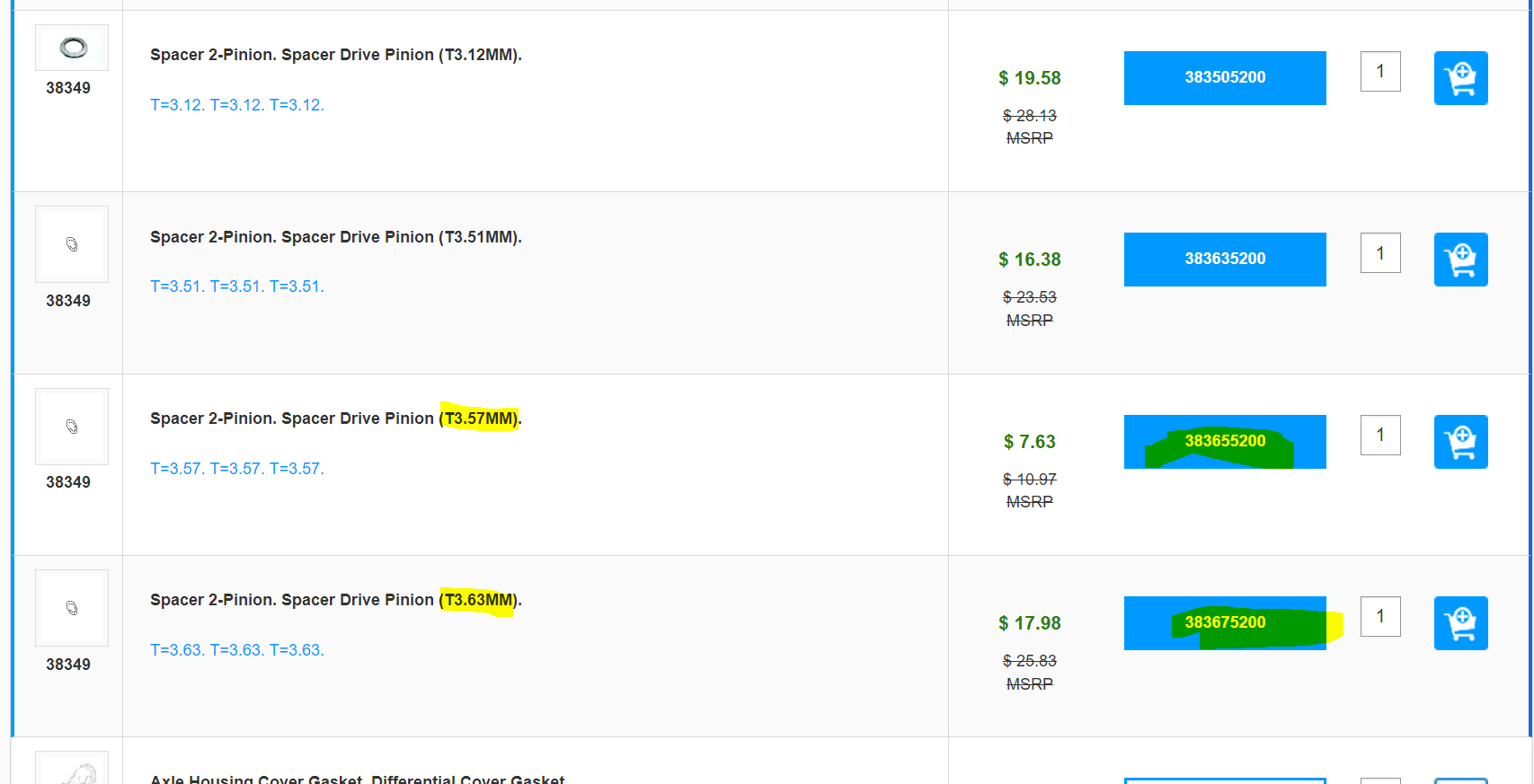
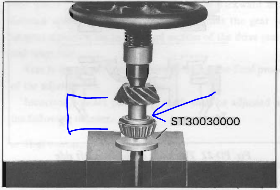
I have waited until I was in the right mood to pick up this project of fixing my back lash issue, and tonight, I was able to take this on. I removed the side flanges, then the one ring gear bolt, so the carrier would come out of the case, and then pressed out the pinion shaft. Rather than removing this bearing (the one in the pic) from the pinion shaft to get access to the washer/spacer (blue arrow) which is sandwiched between the bearing and the gear, I was able to user vernier calipers to measure the washer/spacer thickness. My measurement was about 0.141", (between 140 and 141 thousandths, really). Converting to mm, 0.141" is 3.5814 mm. Looking at what is available on a Subaru website, I found these part numbers: Since my measurement is nearly the same as the 383655200 spacer, it would appear that I only have one spacer which is thicker as an option available. 3.57 mm is equal to 0.1405". 3.63 mm is equal to 0.1429". So, order that one, swap it out, reassemble, and recheck gear lash?

-
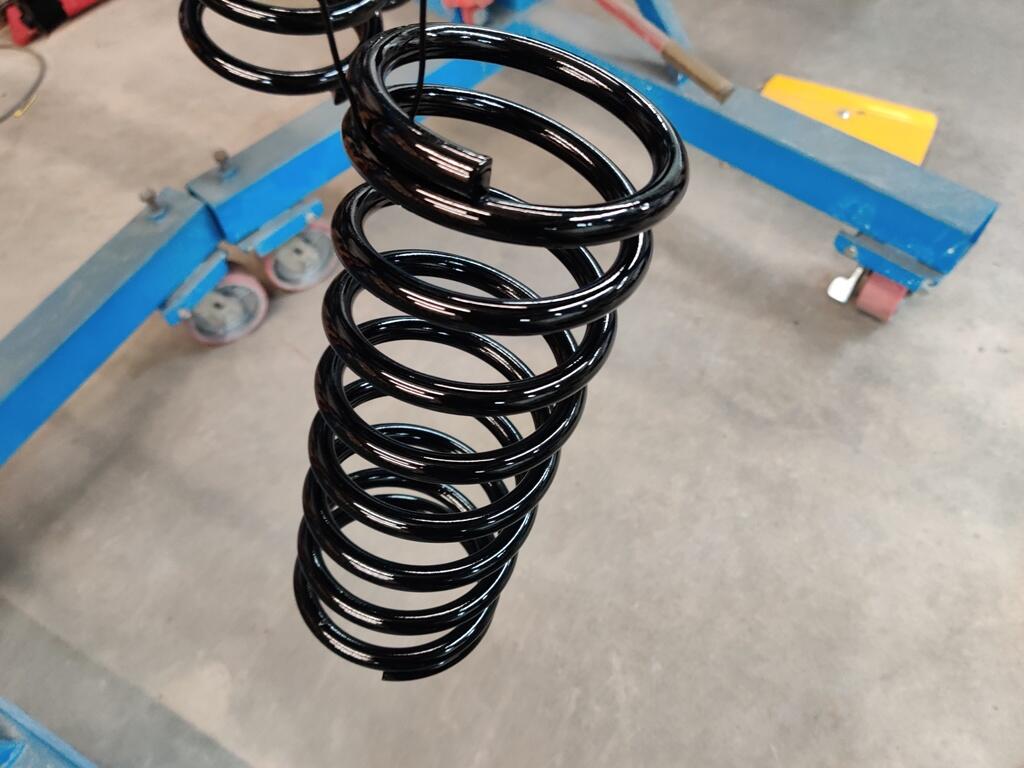
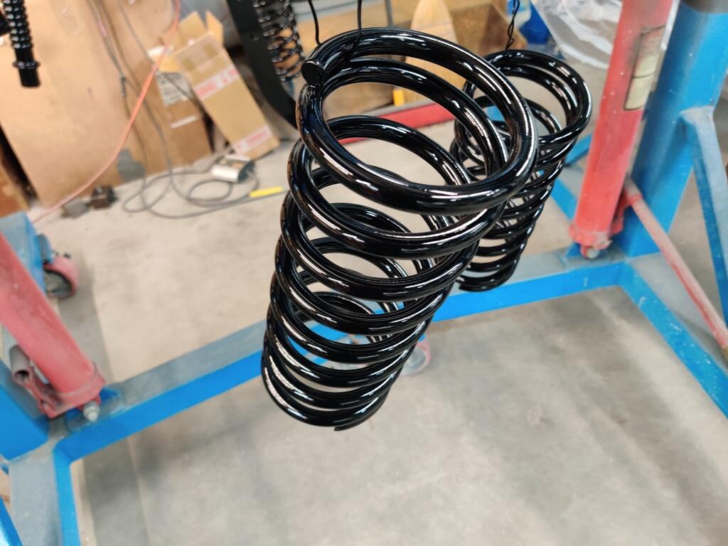
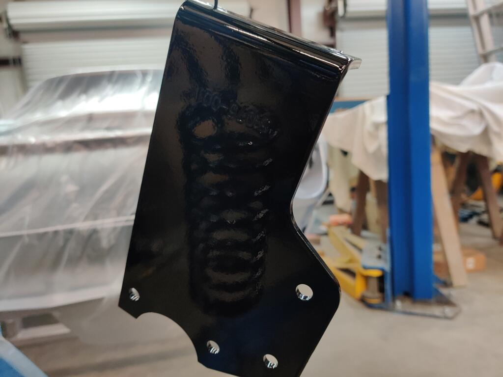
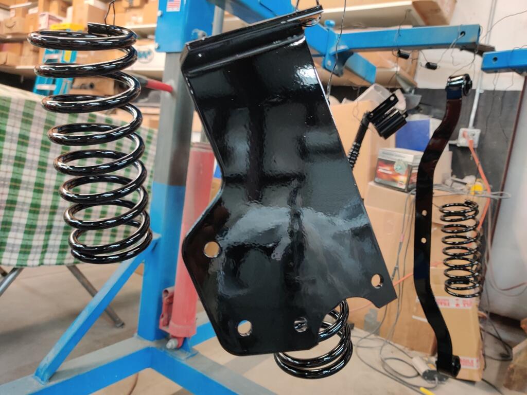
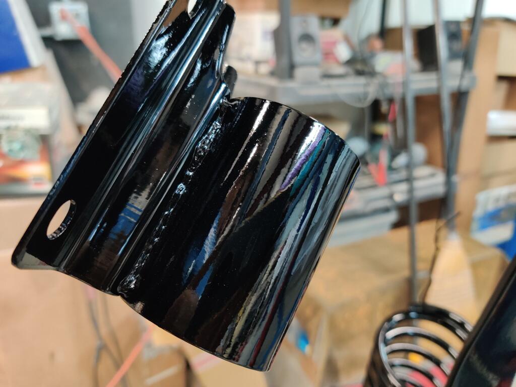
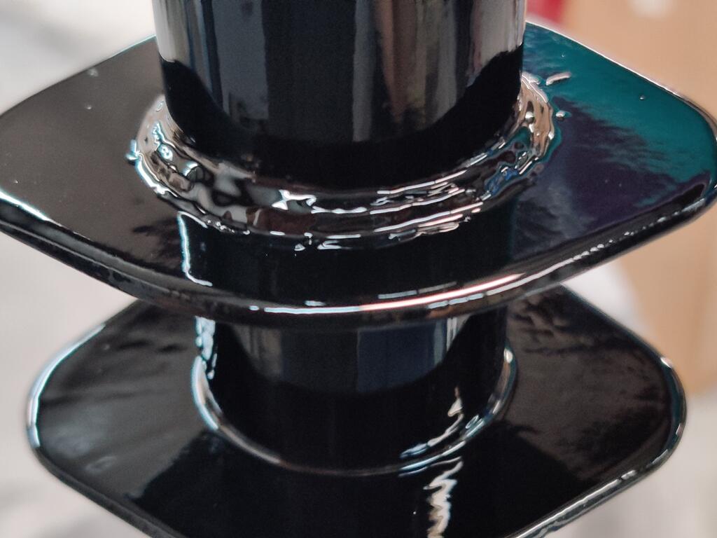
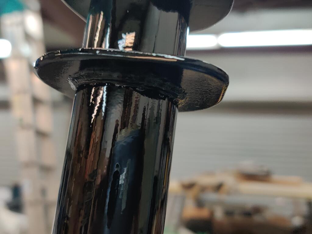
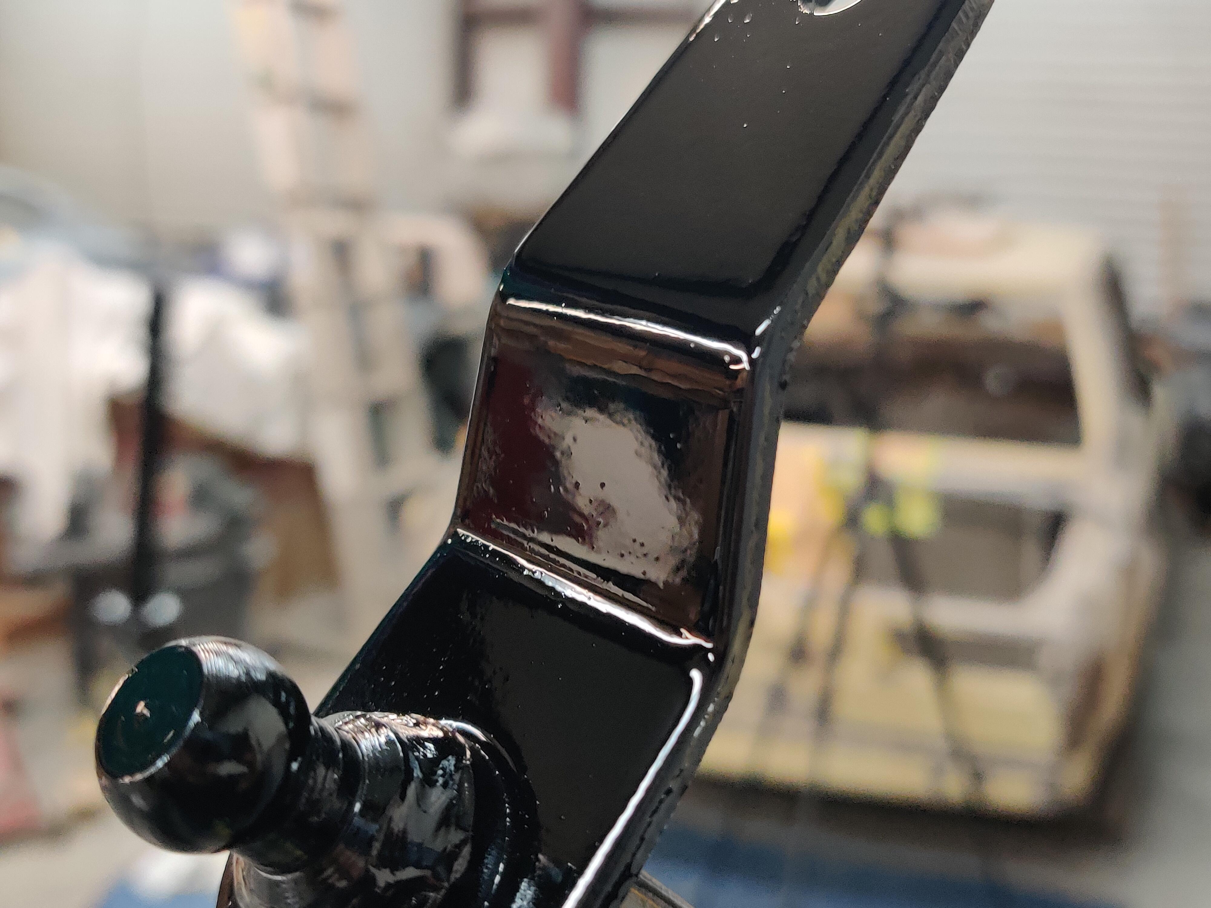
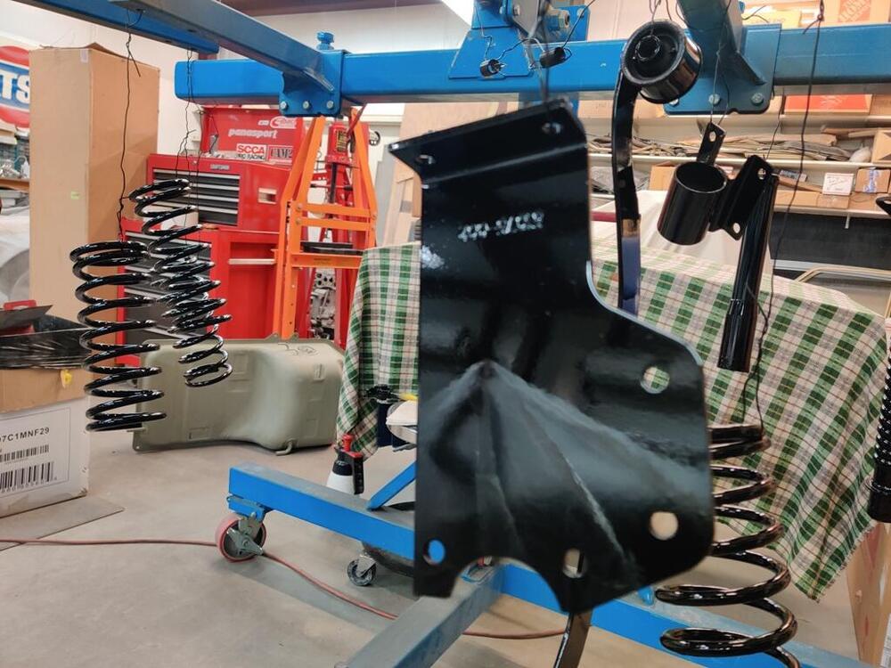
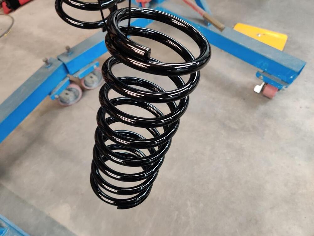
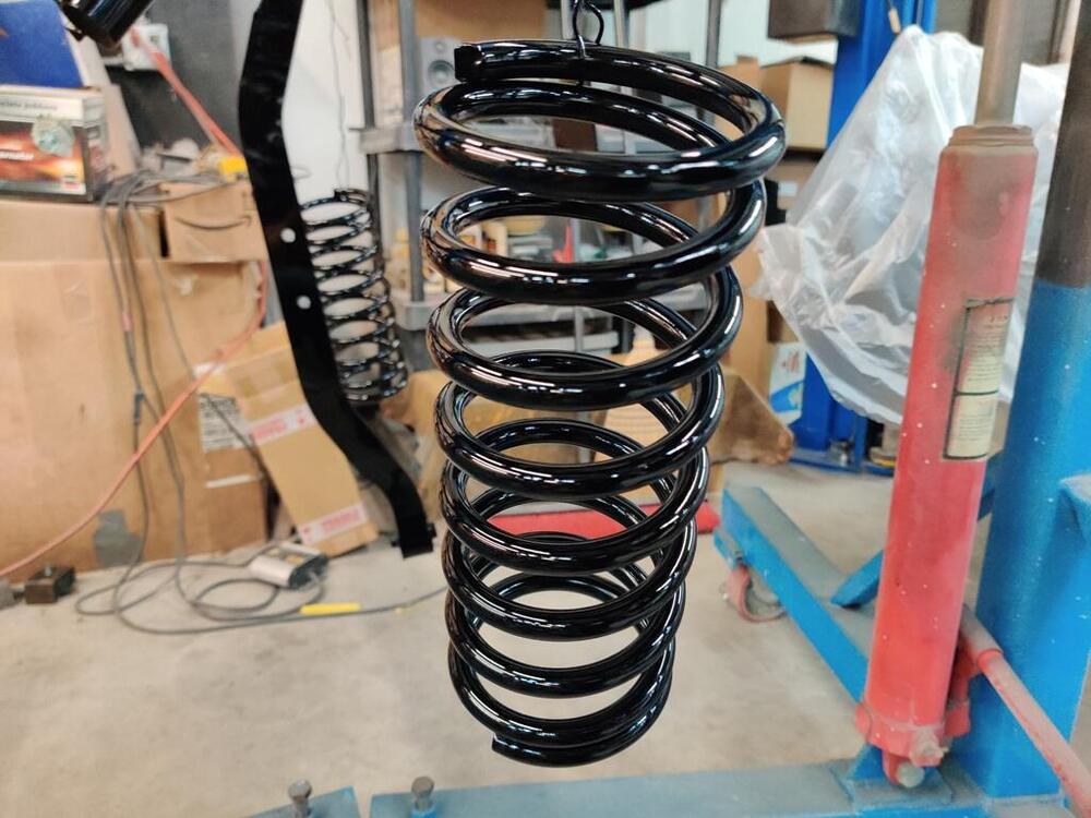
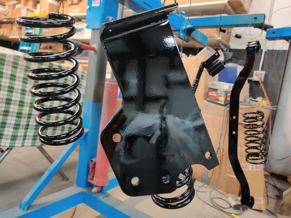
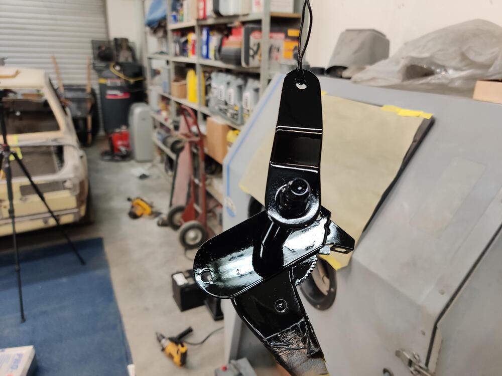
Another batch of parts are now gloss black: The difference between one and two coats is substantial. One coat just isn't sufficient. I didn't quite mix enough paint, so I had a couple of thin areas on a couple parts. I let them dry for an hour or so while I ate dinner and then mixed up some more and reshot the steering rack, transmission mount and the hand brake handle assembly. These Suspension Techniques springs come in a blue powder coat. I scuffed them with red and then green Scotch Brite pads before shooting them with black. Also, while I painted the original suspension "vertical hangers" black already, they will not be installed. Instead, I will be using these which came with the Suspension Techniques rear anti-roll bar kit. These were black powder coated, and I did the same scuffing before painting them with this gloss black. I continue to use 10% (by weight) of flattening agent with each batch of black that I mix up. I will let these dry overnight and tomorrow, hope to get the engine and transmission together and installed in the car.


-
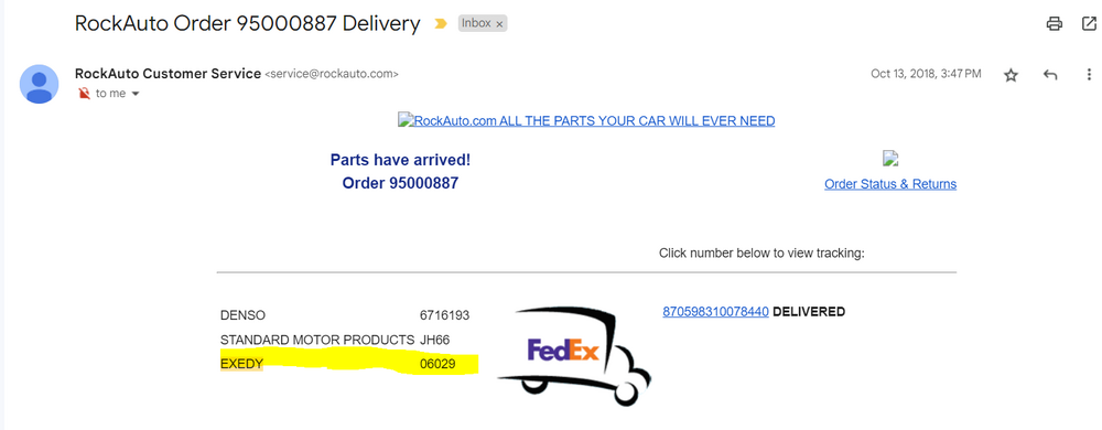
No problem - 06029 is indeed the part number I ordered... and from RockAuto at that:
-
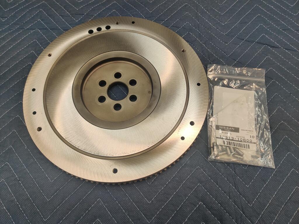
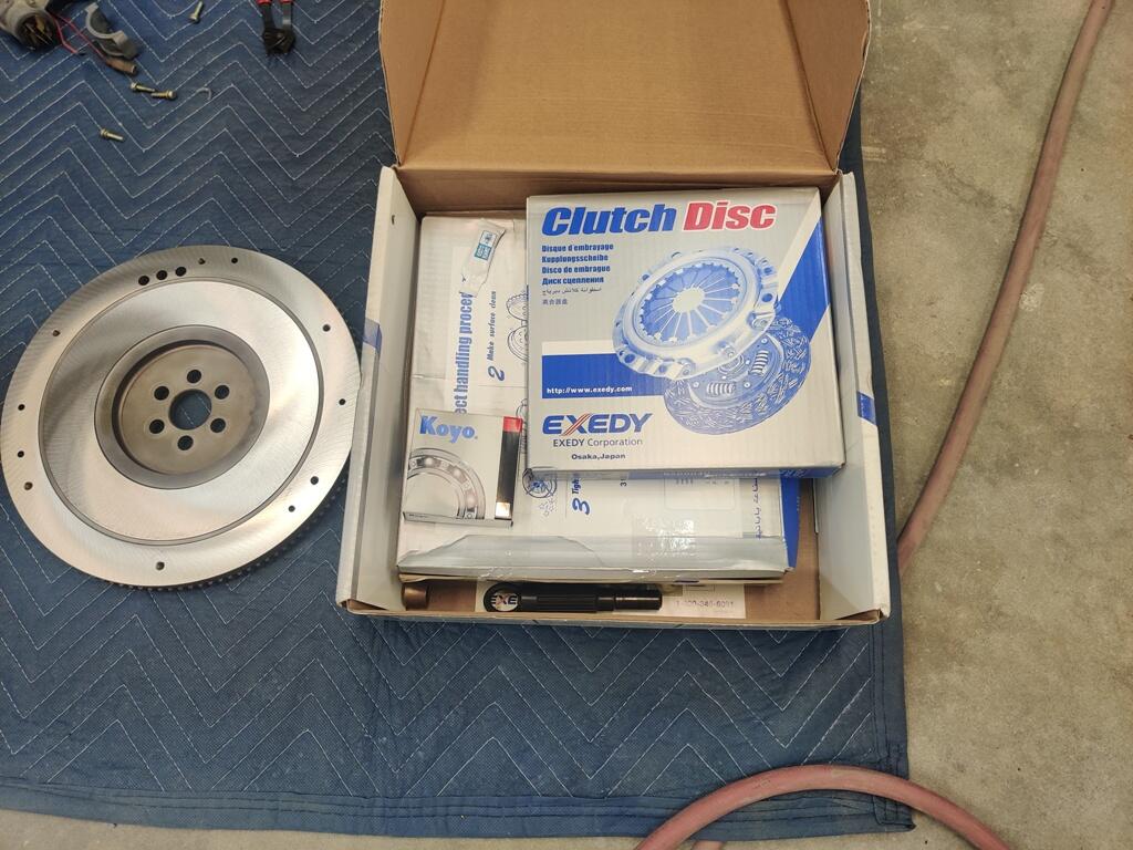
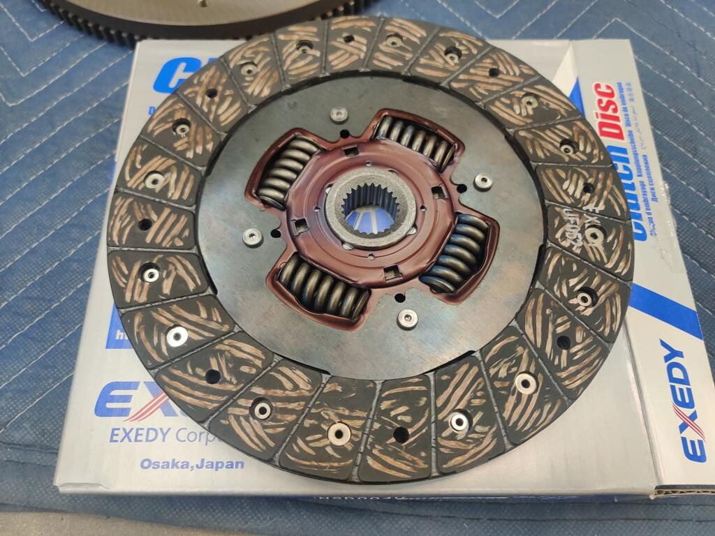
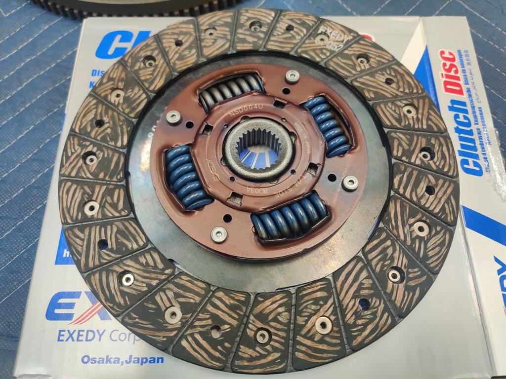
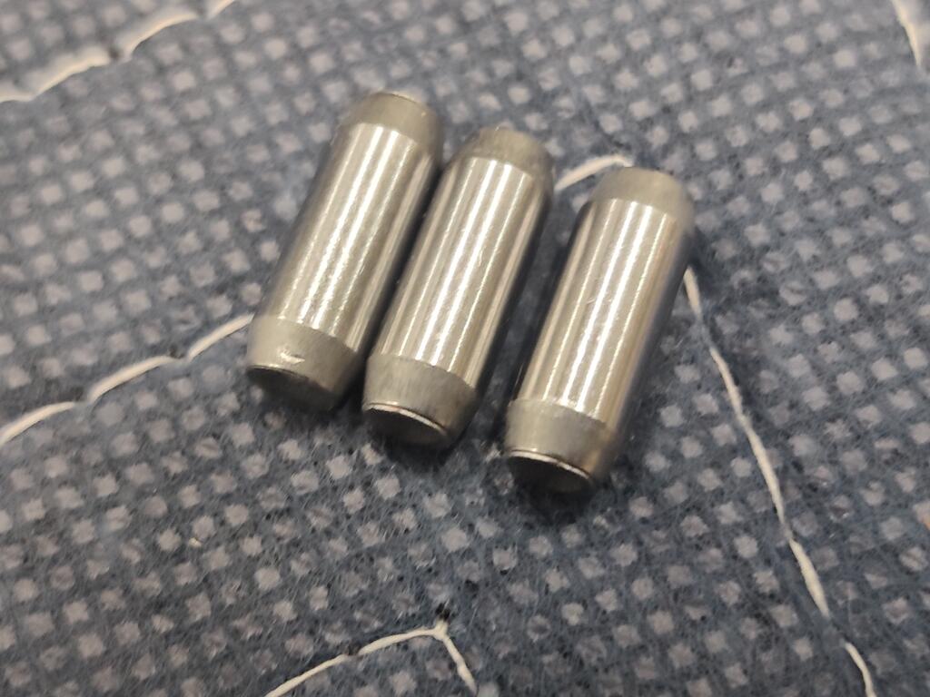
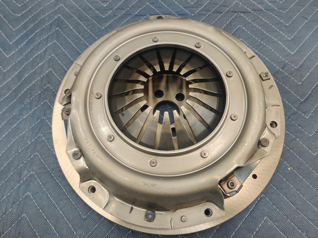
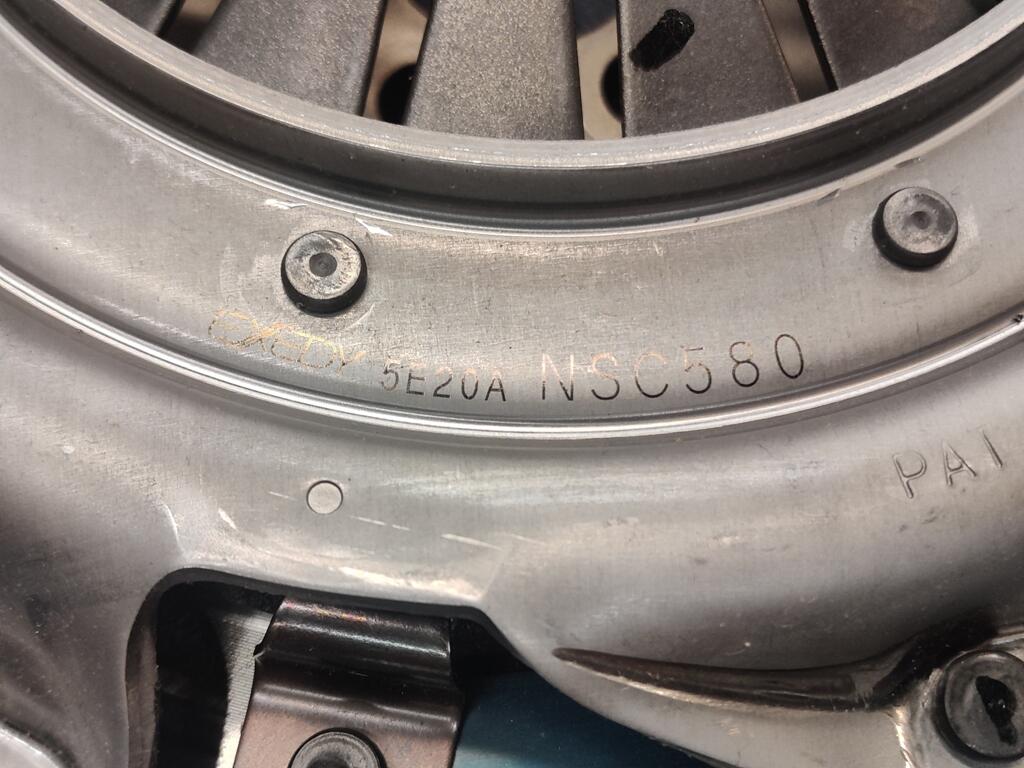
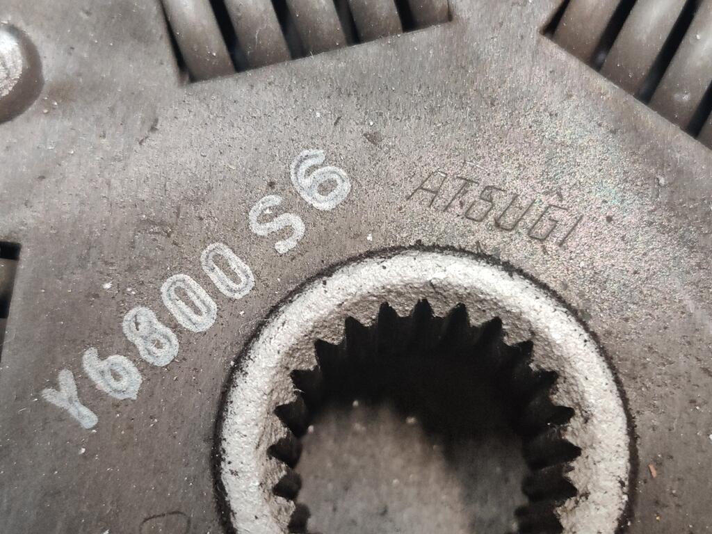
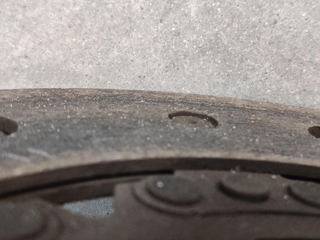
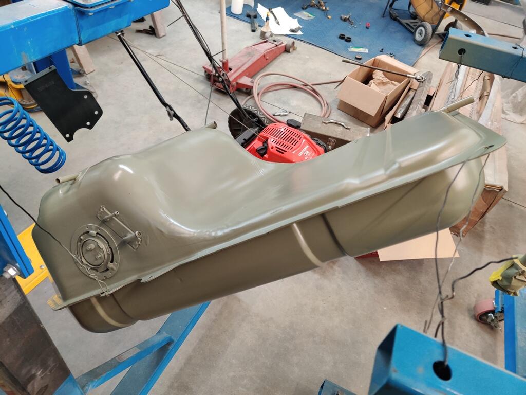
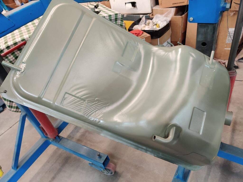
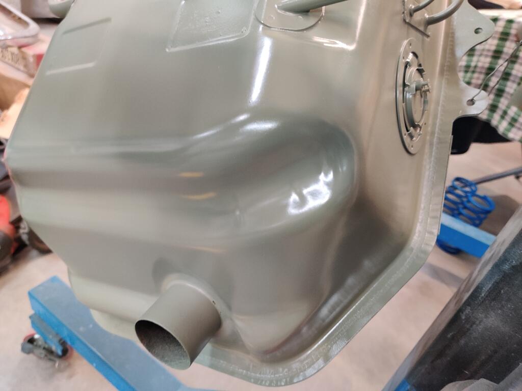
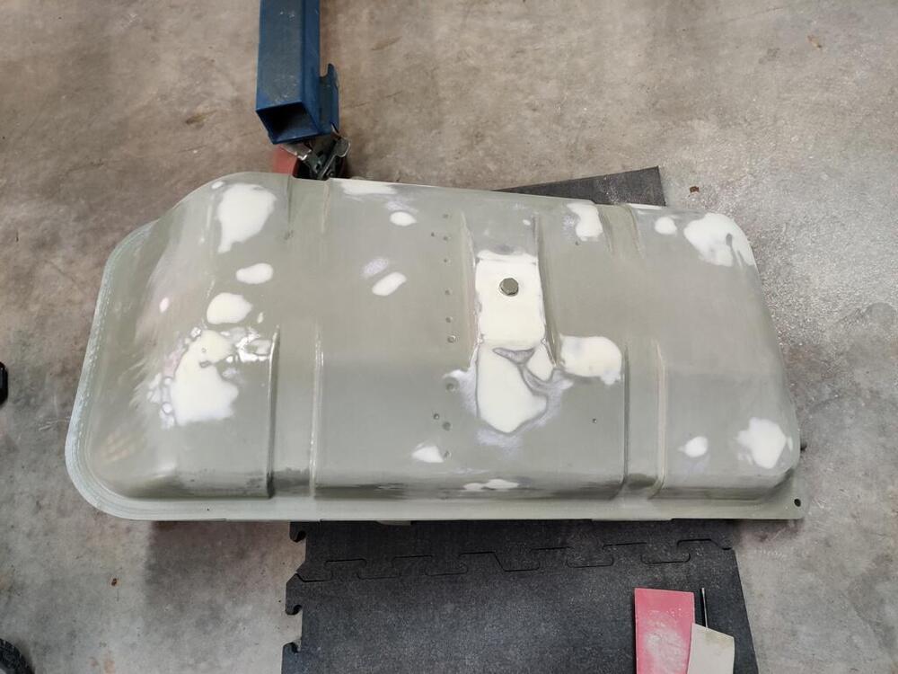
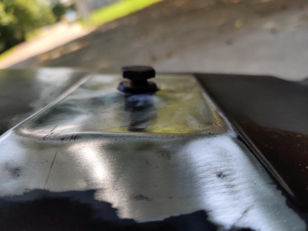
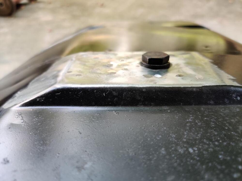
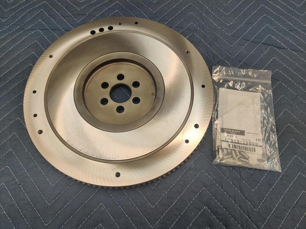
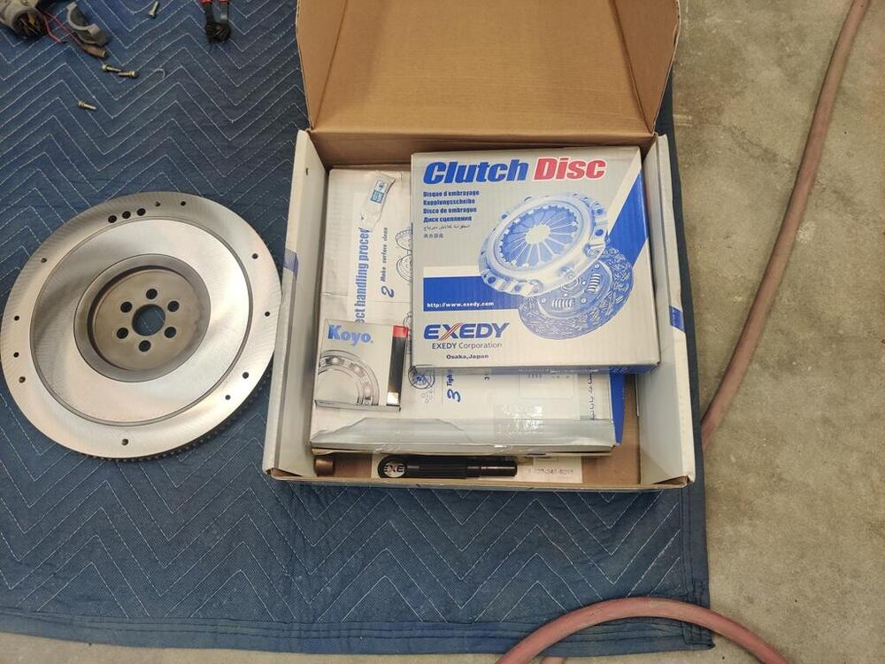
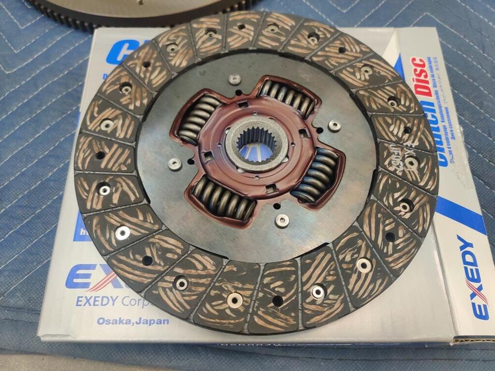
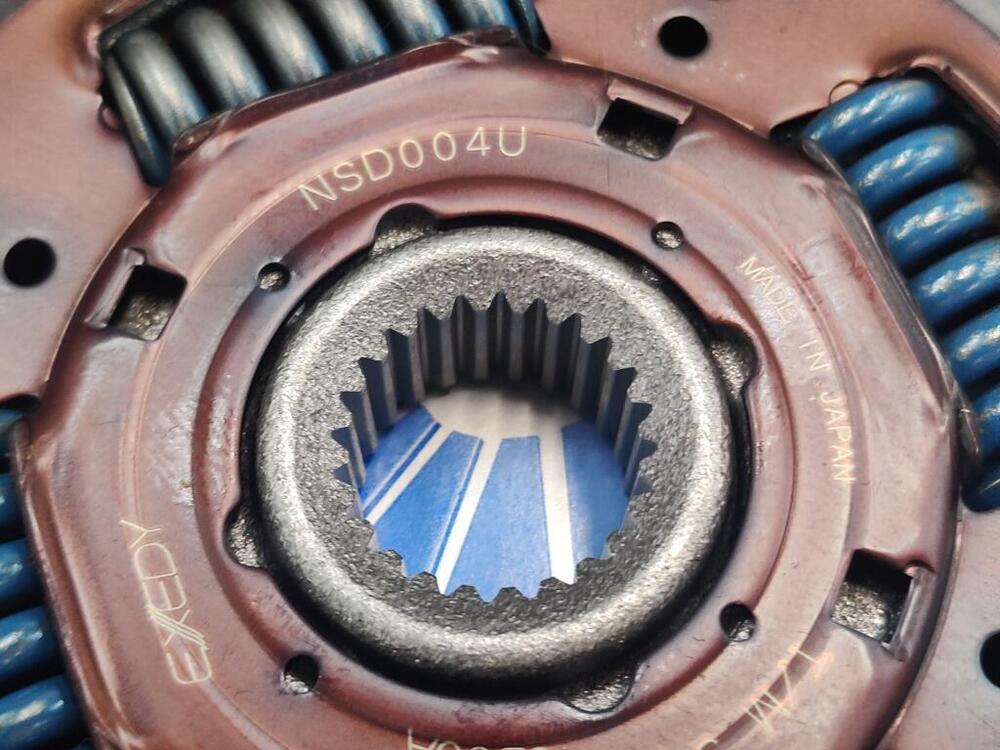
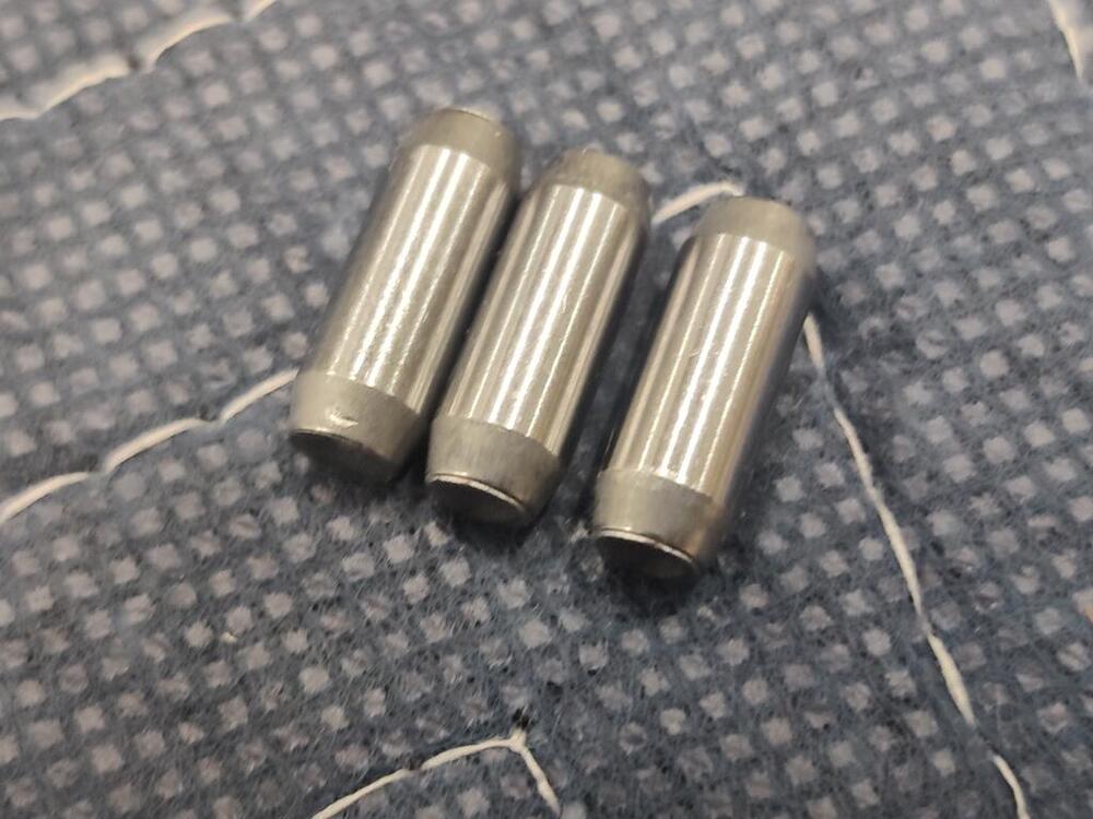
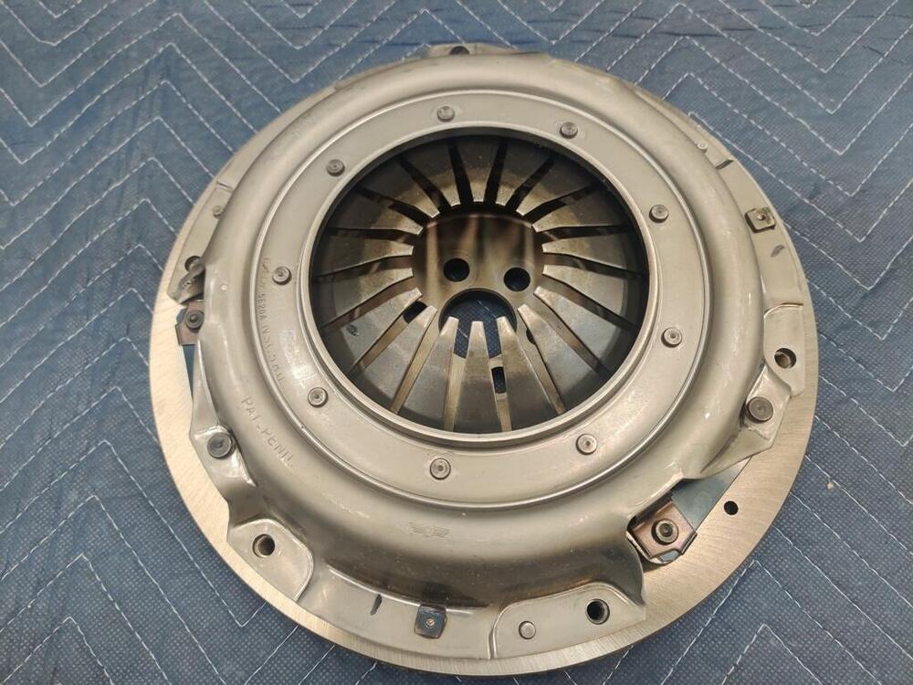
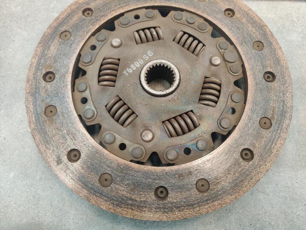
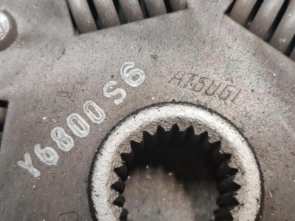
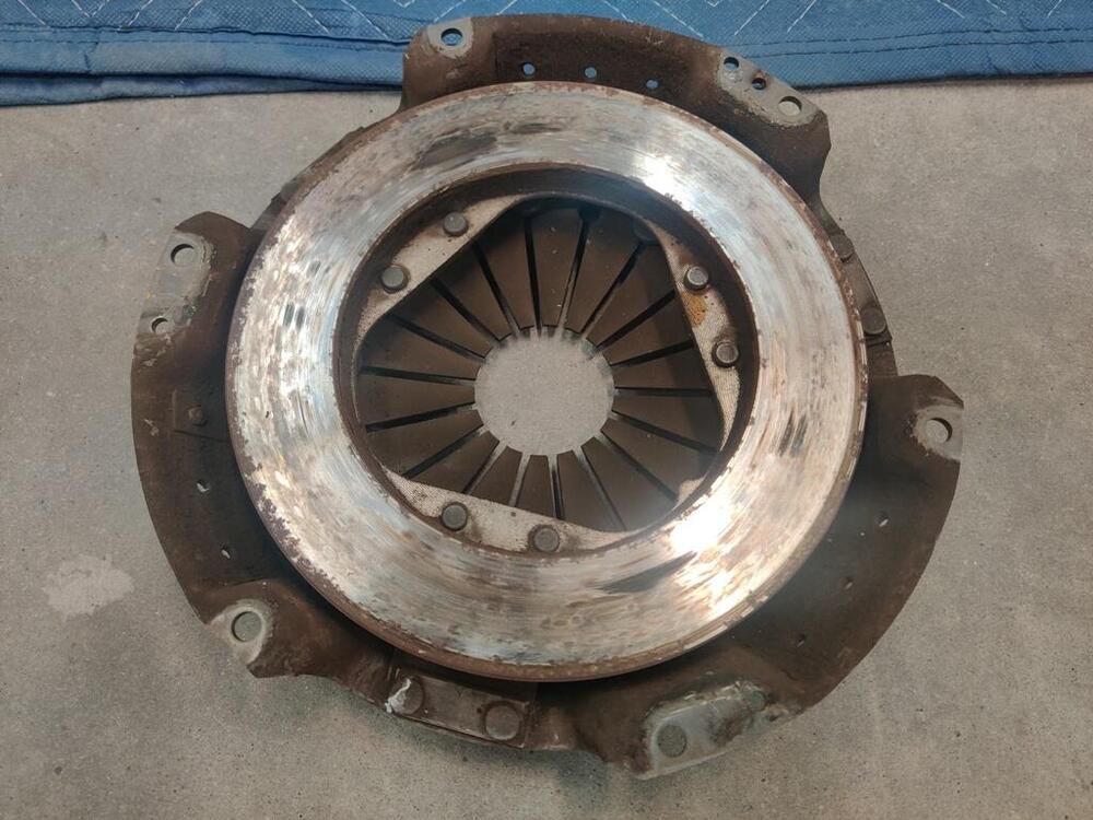
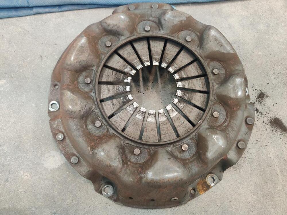
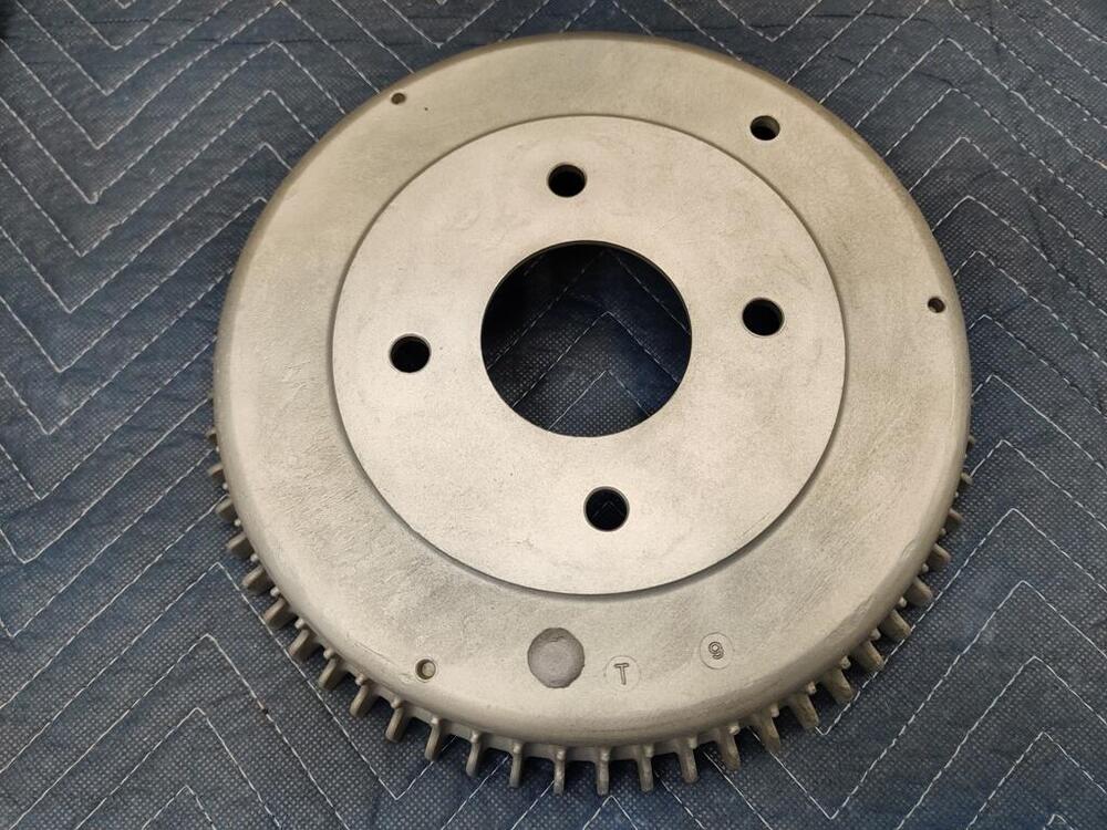
I got delayed with painting the next batch of parts black because I forgot that the gas tank needed a bit of filler work. Where I left off with the tank, I had used the pin welder to pull low spots. When done with that, I blasted the exterior of the tank with black diamond (lightly) to remove the black paint the radiator repair shop had refinished the tank with. Then I glass bead blasted the exterior of the tank to smooth finish. I epoxy primed the tank a few days ago, and planned to paint black about 8 hours later, but again, forgot about needing to do the filler work. I was held up from connecting the engine to the transmission because the flywheel needed resurfacing and while removing the pressure plate alignment dowels, they got destroyed. So, I had to order new ones. I was able to get the machining done this past week (along with having the rear drums turned). Some very shallow rust pits remain, but taking it down further doesn't look to be called for to me. I chose to go with an Exedy clutch kit. PP and clutch that I am replacing were manufactured by "Atsugi": I should be able to install the engine and transmission this weekend.


-
It's time to ship off my chrome parts to someone - it is time to make a decision. So, I am revisiting this topic and wondering if anyone else has received re-plated bumpers from a place other than those mentioned that they would highly recommend? My consideration list currently includes: https://www.tricityplating.com TN https://www.redspartsattic.com TX https://speedsportchrome.com TX https://www.ogdenchrome.com UT Reds Parts Attic is a place I found looking on my own online. I got a nice email from the owner of redspartsattic back in July of 2022 - thought I would share: Thank you for contacting us for our chrome plating services. I appreciate the opportunity to earn your business. Our crew has well over 100 years combined experience. I know they will do a great job for you! Your parts will be plated using Copper, Nickel and Chrome. (TRIPLE CHROME PLATING) We go through multiple steps and procedures to achieve a mirror, chrome finish that will last. Not all chrome shops are the same, or complete the work the same way. We will treat your parts as if they were our own and not cut any corners. On our website you can view samples of our work under photo and video gallery. Please take a moment to read our previous customer testimonials. We take pride in customer service and chrome quality. We stand behind every order we do! Chrome Estimate: Bumpers with 2 guards - $1000 each Pricing will vary depending on your parts starting condition. Price includes minor straightening and dent repairs. We are currently running a 6 – 8 week turnaround time. Texas residence will be charged sales taxes. Price does not include shipping costs. I can provide you with a quote based on your zip code. We use FedEx and receive a discounted rate. I can provide you with a pre-paid shipping label. Please ask and I can help with instructions. You may package and ship parts using your own method. Please securely package and include all your contact information inside the box. Please email me your tracking information and I will personally keep a look out for your parts. Once parts are received I will contact you to discuss your order. Please let me know if any questions. I’m your main point of contact from start to finish. Customer service and communication are very important to me. I check and respond to my messages daily. Thank you for the opportunity to earn your business. Best regards, Joe DelVecchio Owner Phone: 713-299-1555 Call any time Email: joe@redspartsattic.com Website: www.redspartsattic.com Testimonials: Customer Reviews Photos: Photo Gallery
-
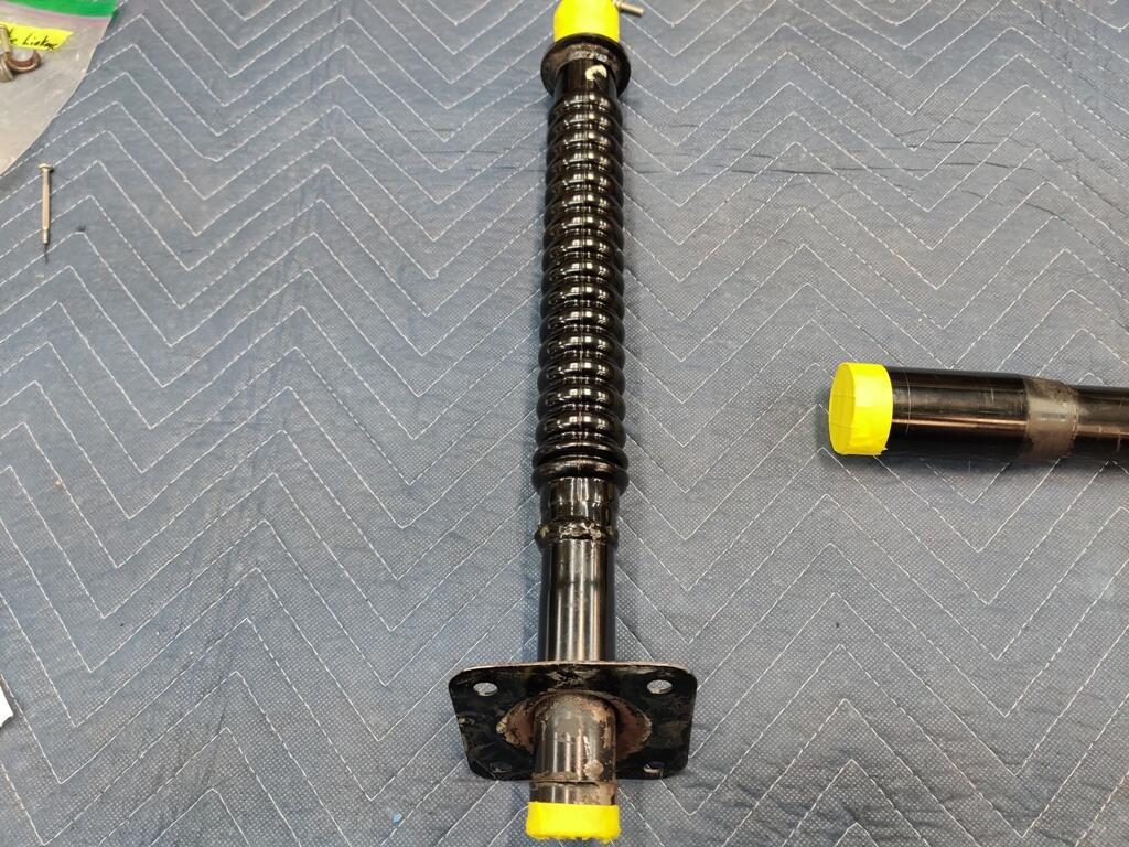
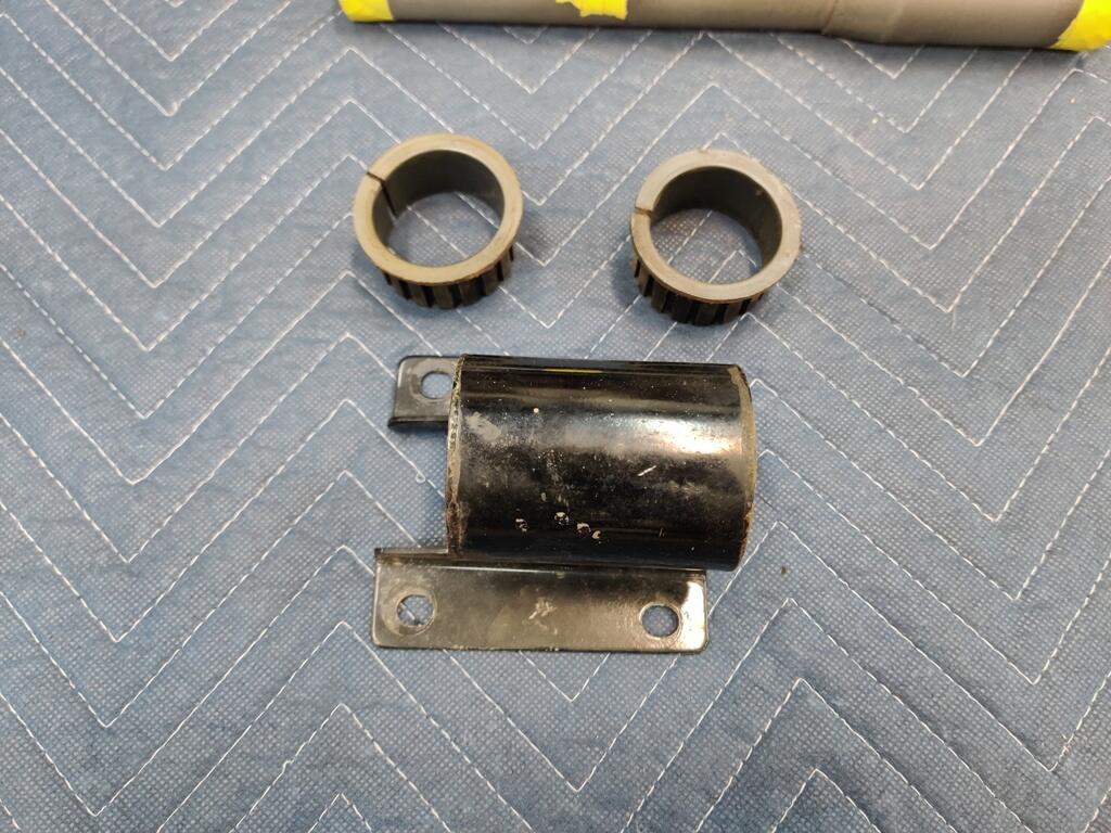
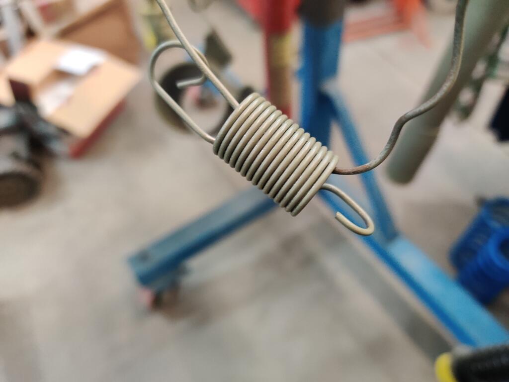
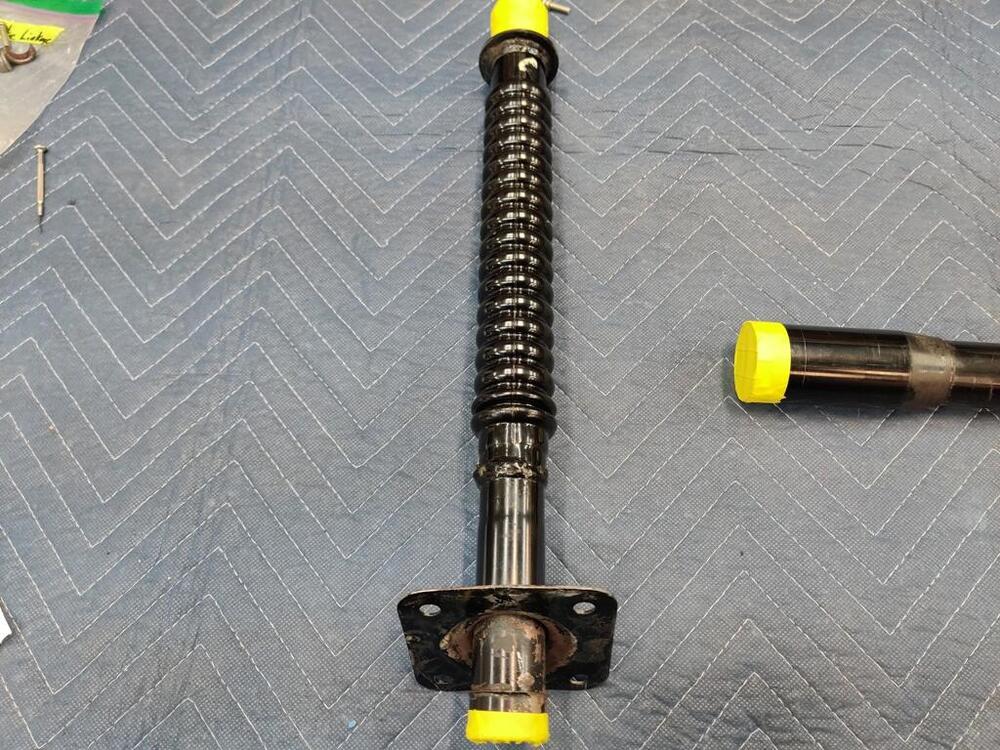
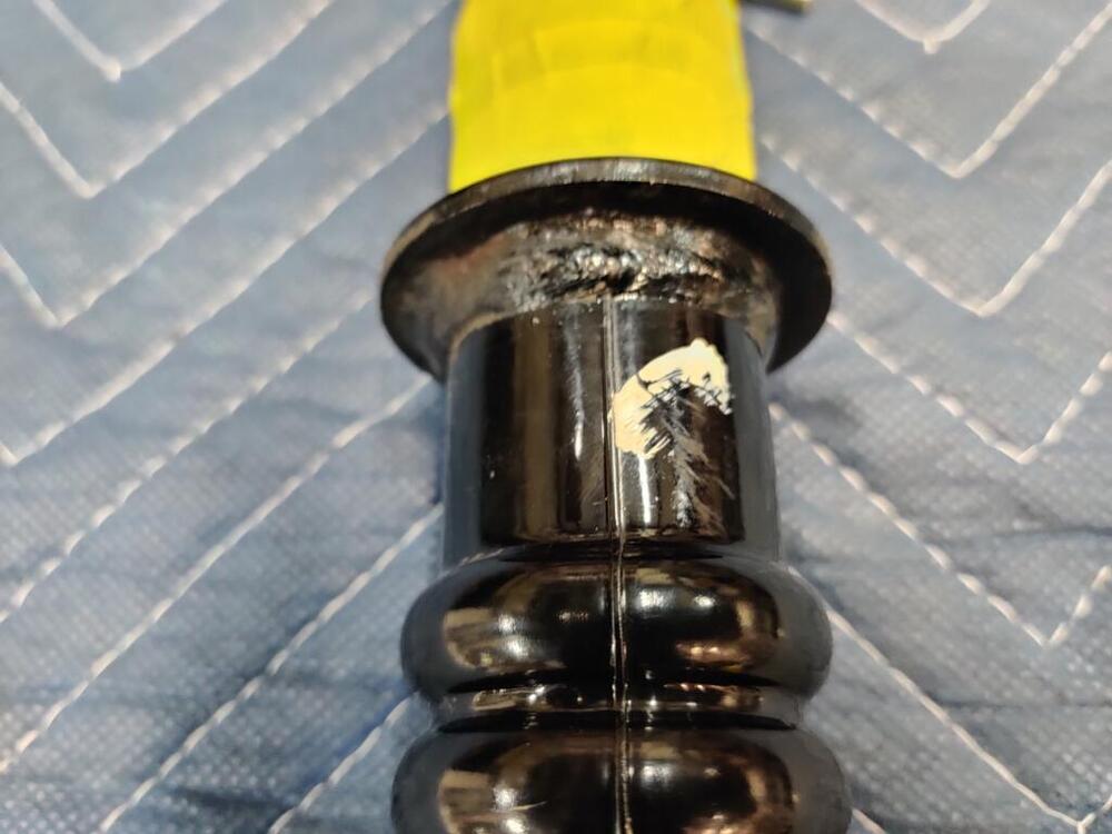
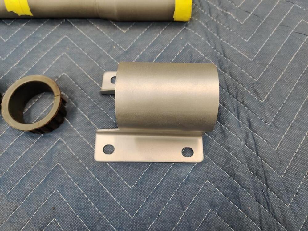
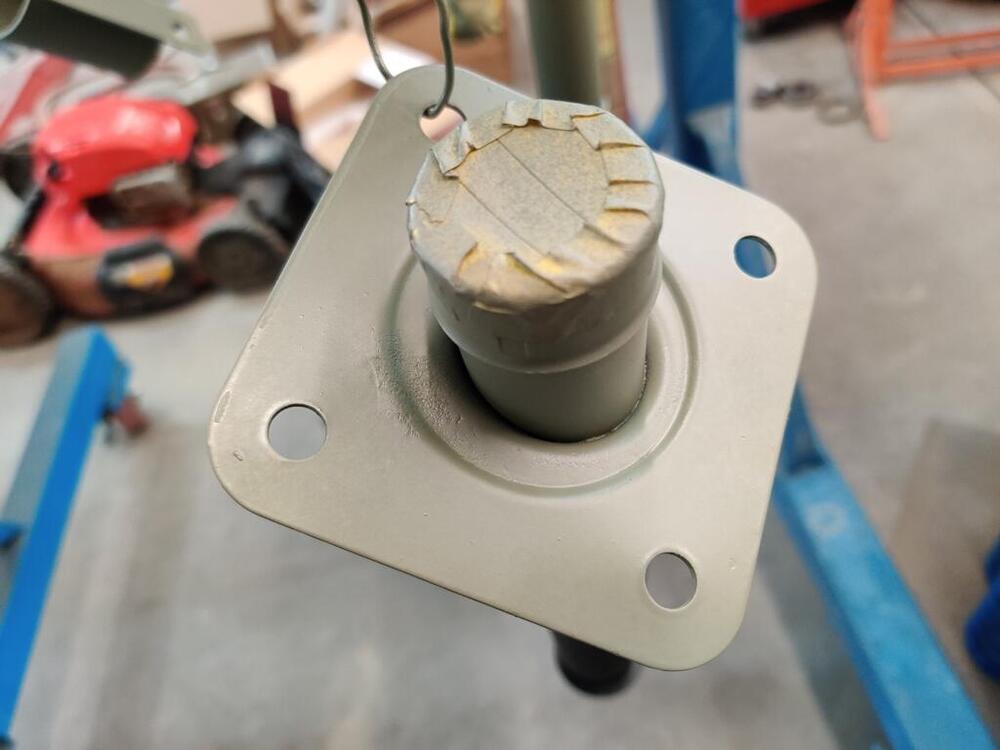
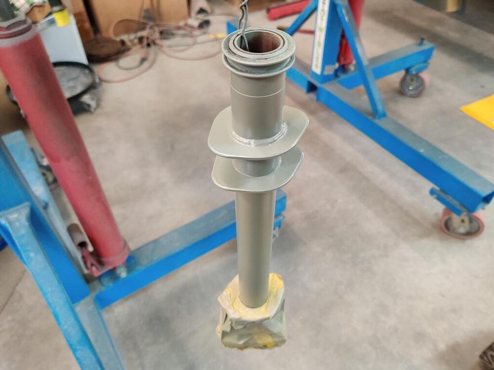
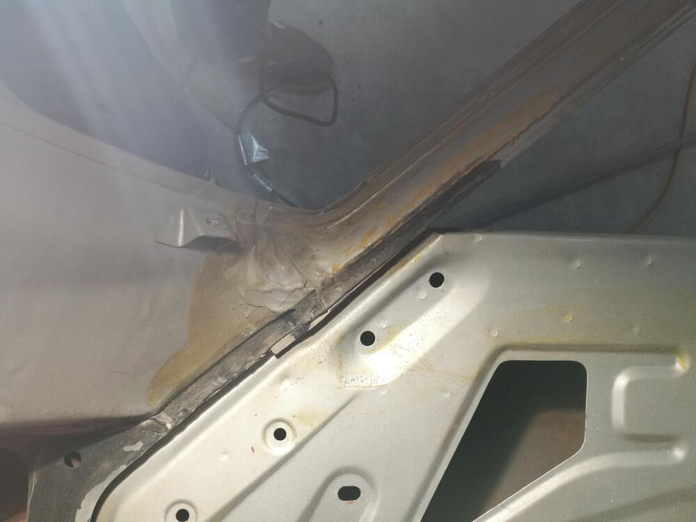
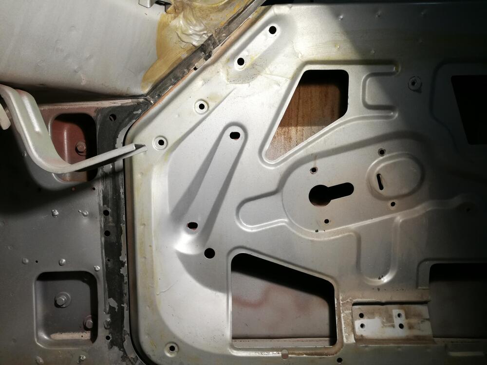
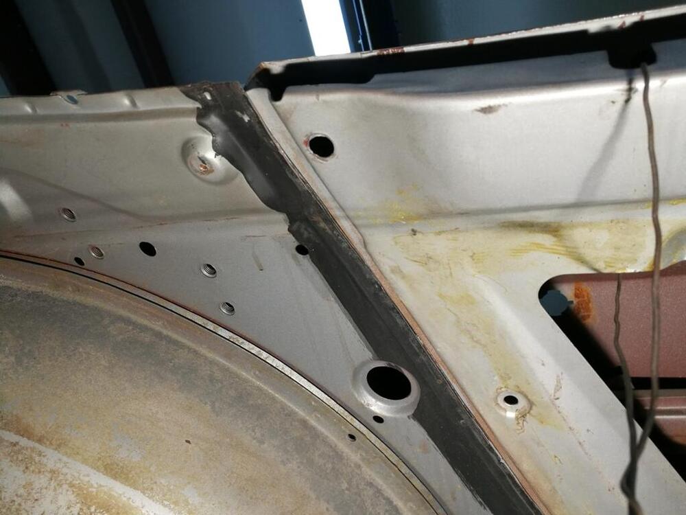
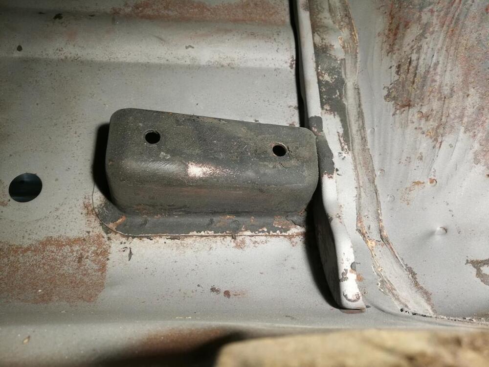
One of the last parts I needed to disassemble, clean, strip and repaint was the steering column. Taping up so I can glass bead blast without getting beads inside: Odd white (I think) paint blotch. I removed the plastic bushings, which were glued into place on the steering column bracket: Springs are for the handbrake cables. Epoxy priming session here is nearly everything that is left that I have yet to paint black: Gas tank - sand blasted - glass bead blasted and epoxy primed. Tomorrow, I will paint these and some other parts black.


-
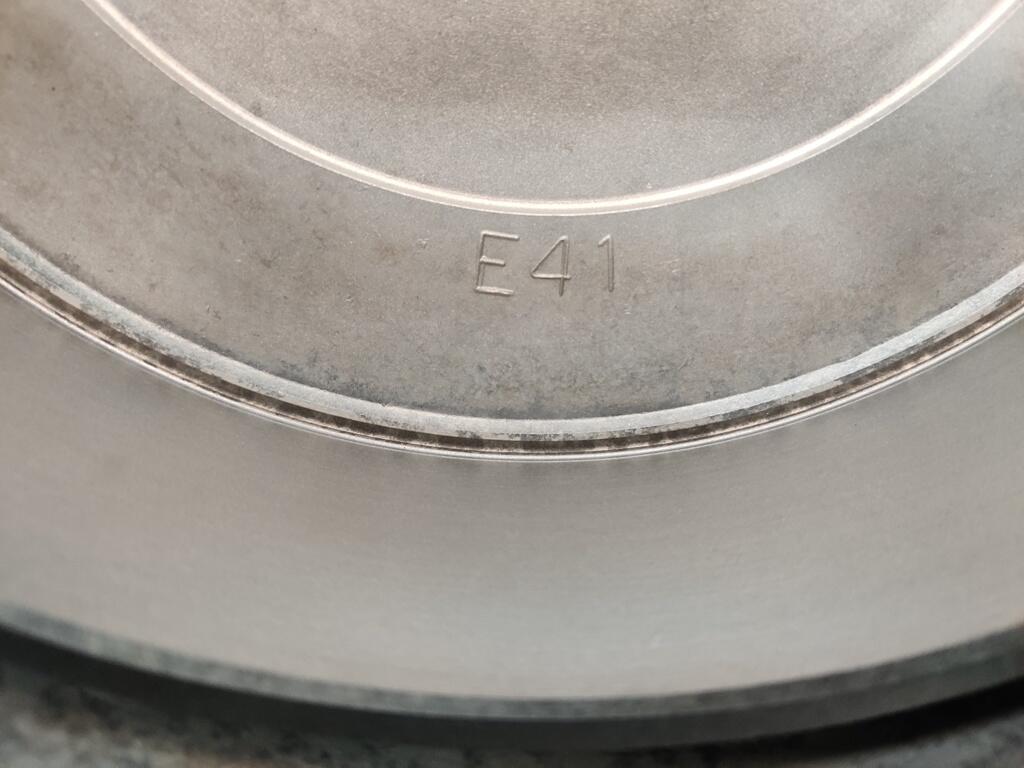
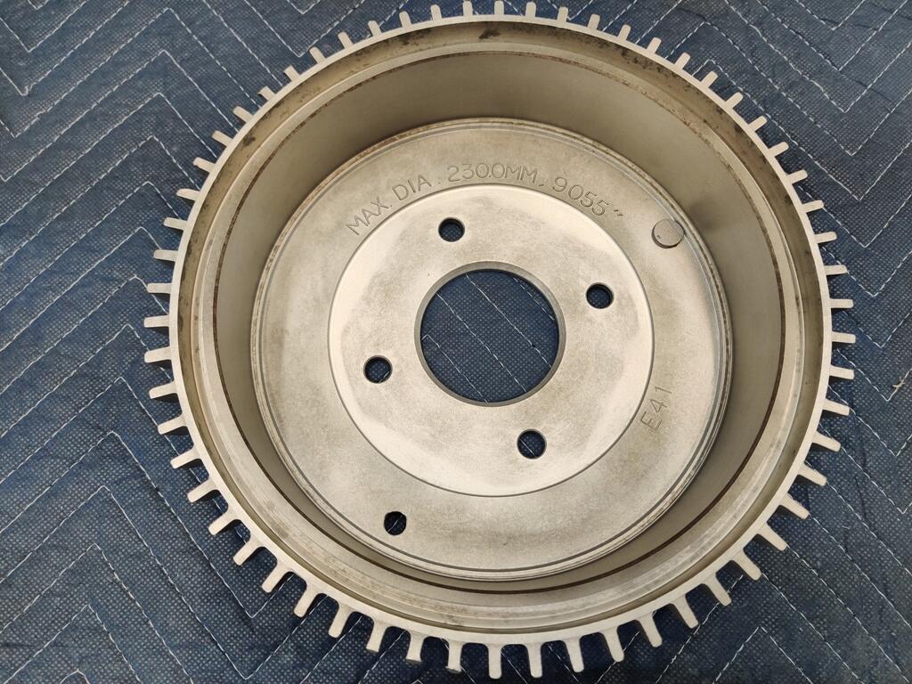
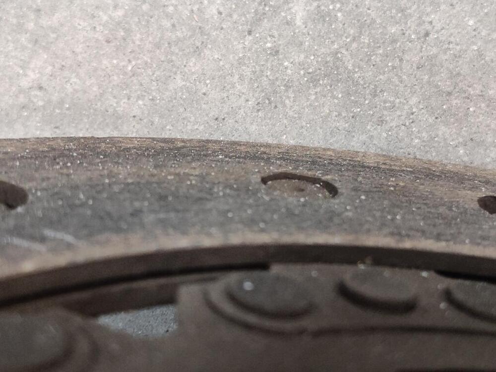
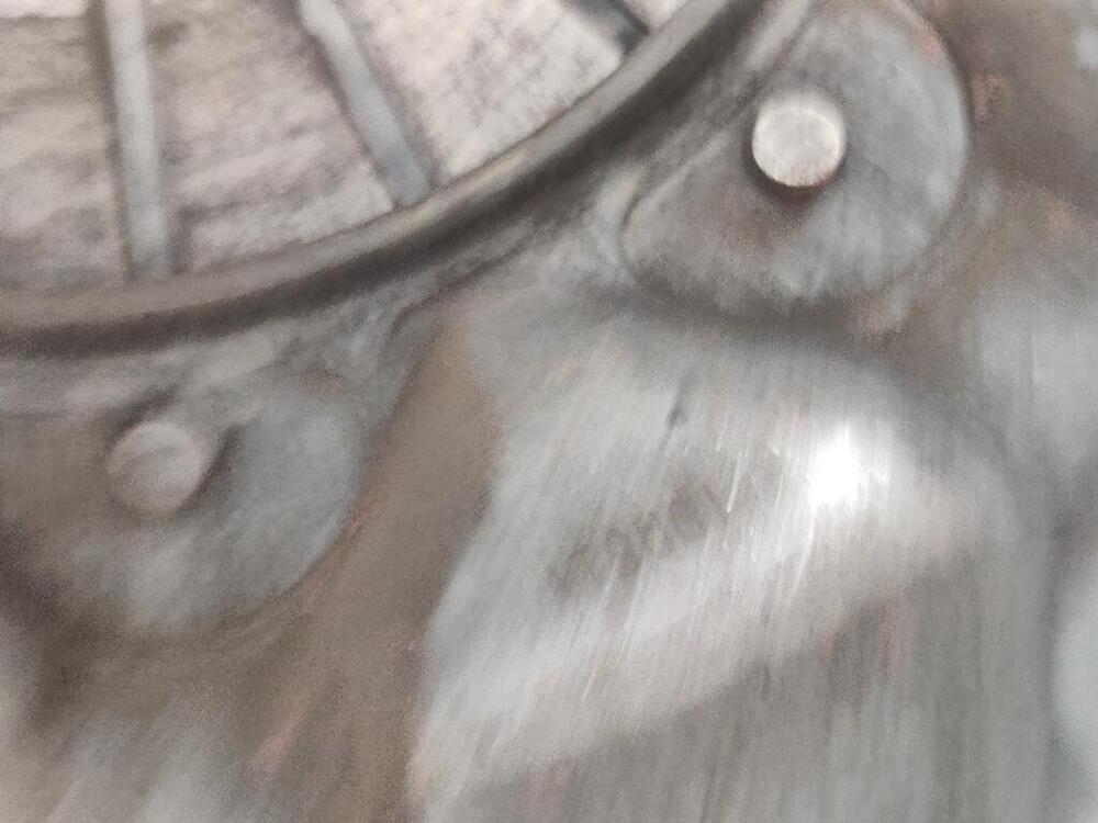
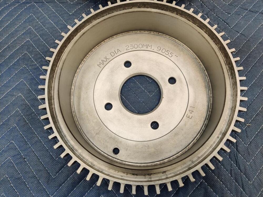
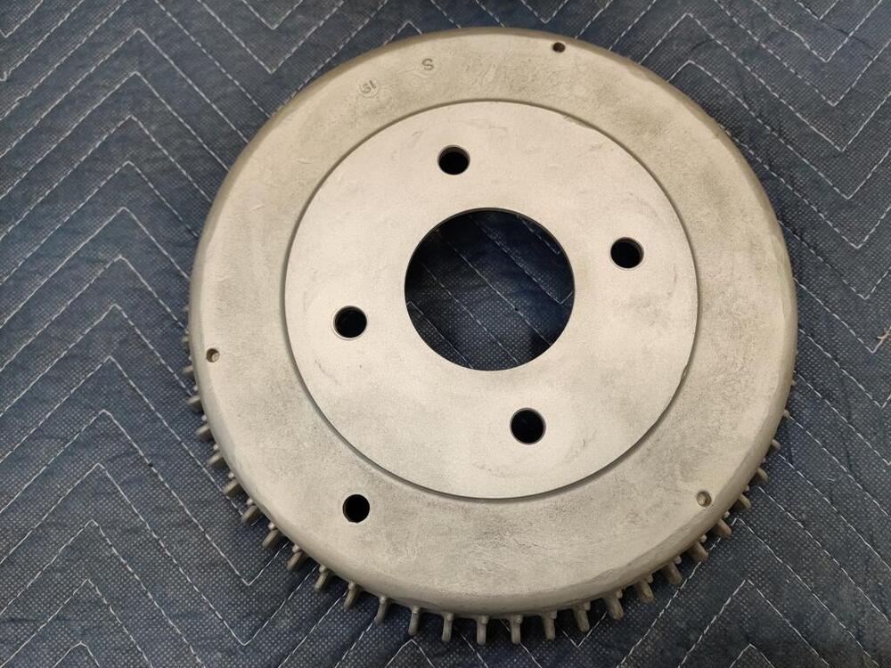
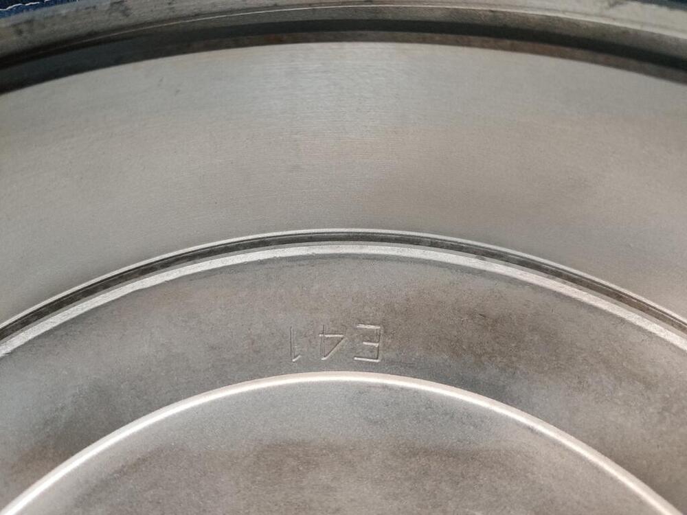
In addition to the black out, I had the drums "turned" and then I glass bead blasted them: Unfortunately, I previous owner banged pretty hard on them with a hammer around the outer circumference. But, that is not seen when the wheels are mounted.


-
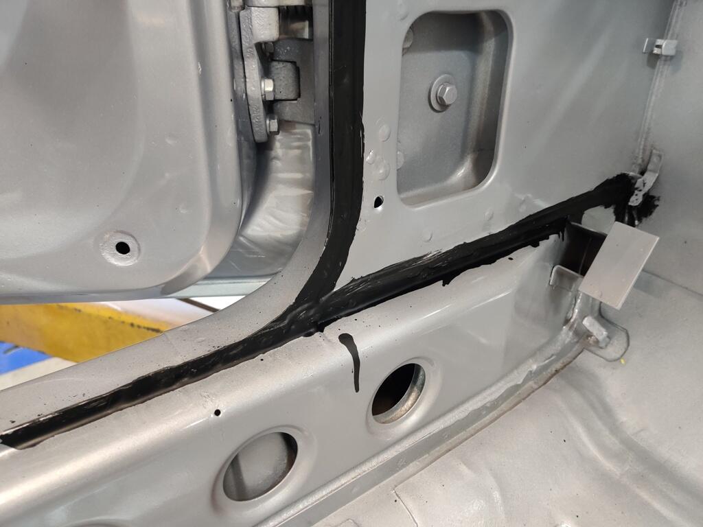
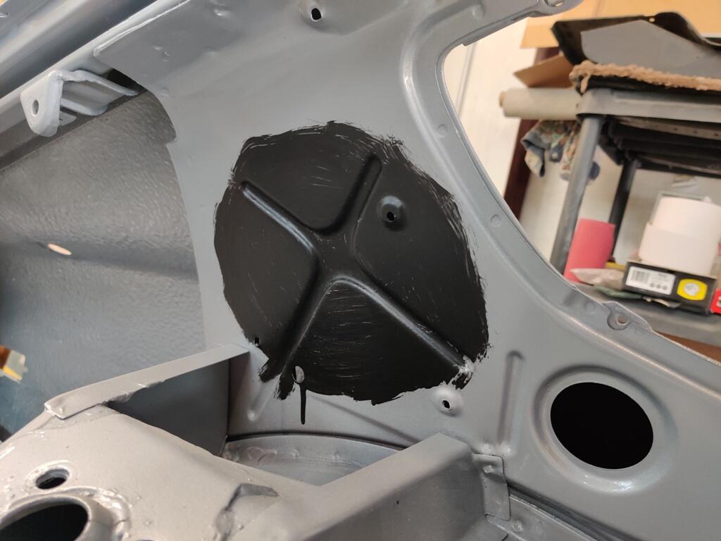
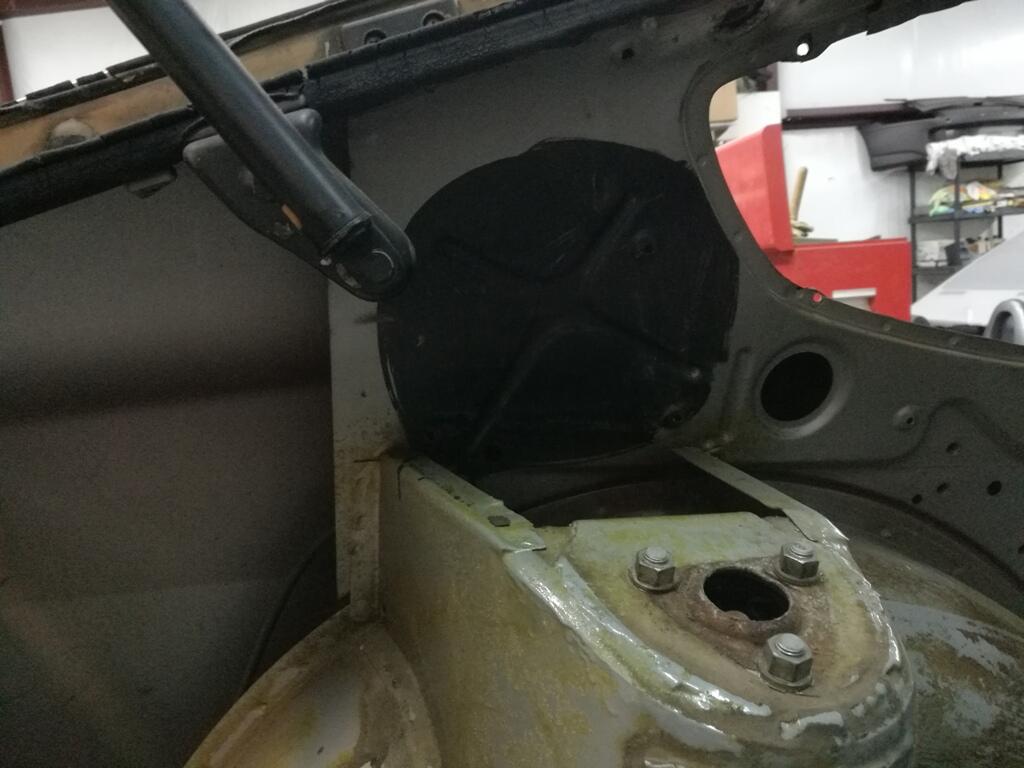
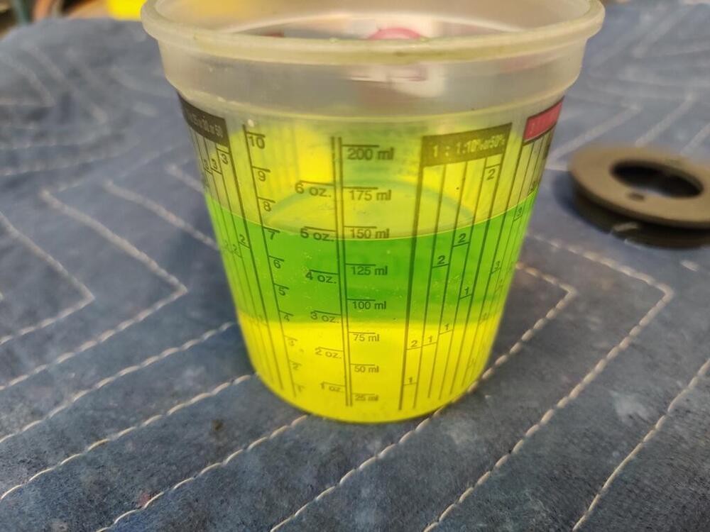
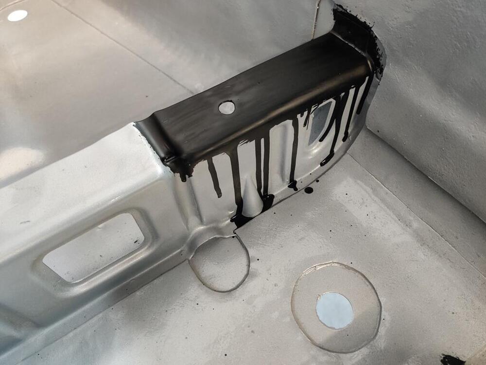
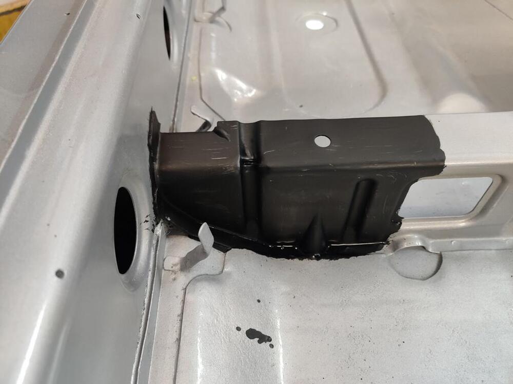
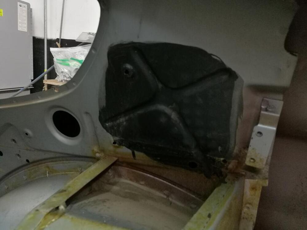
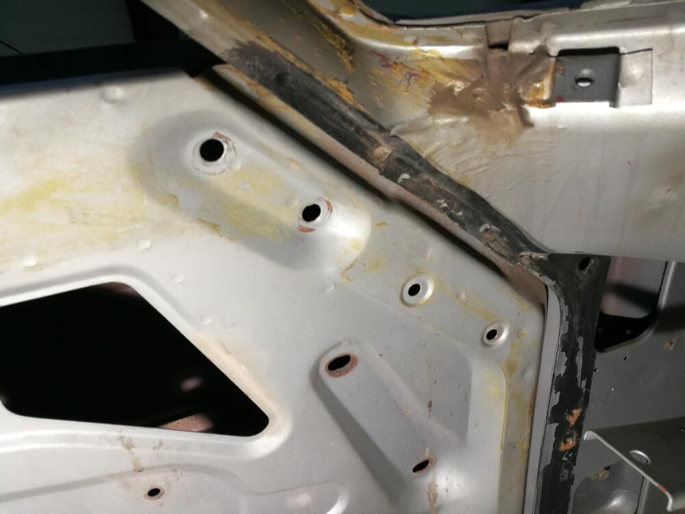
Thanks guys! I had some fun this week end with some Krylon flat black paint. I sprayed it into a small cup and then used a paint brush to attempt a similar look with the "black out": Whoops on the runs and drips - ha ha ha 😆 Here are my original reference pictures: It was fun attempting to replicate the original "black out"


-
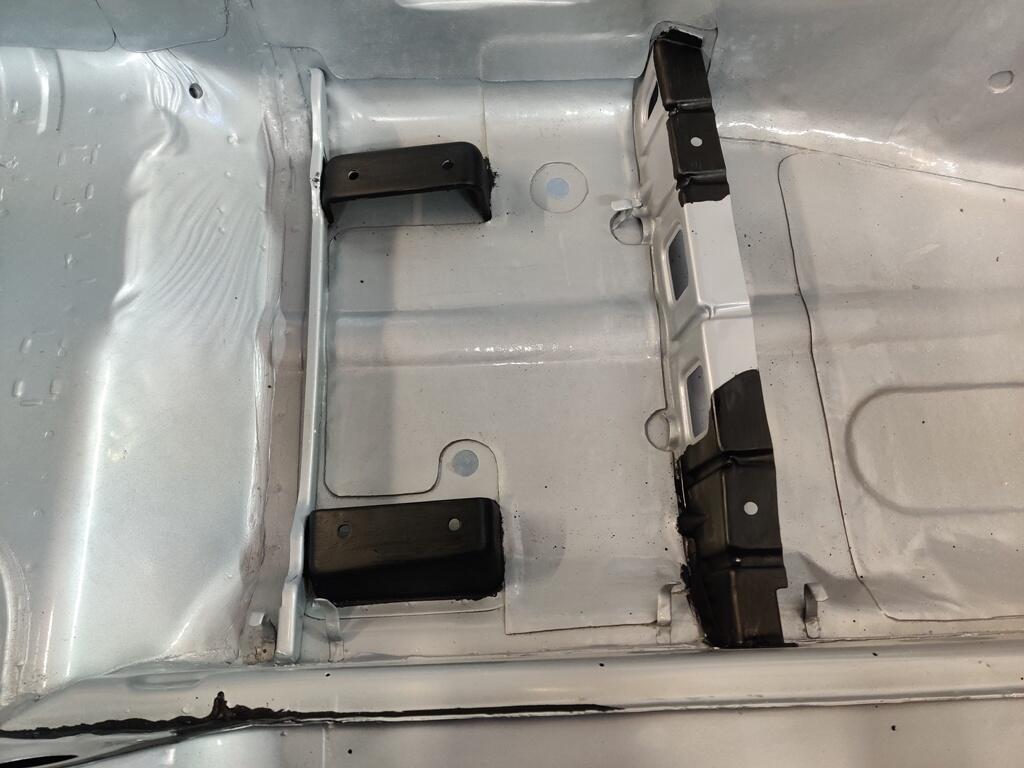
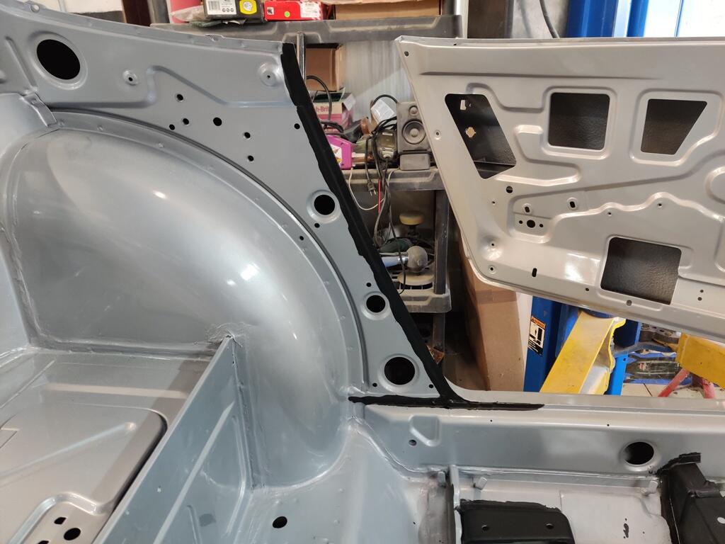
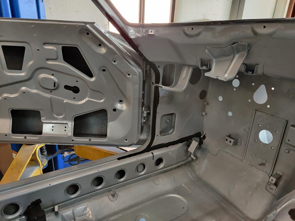
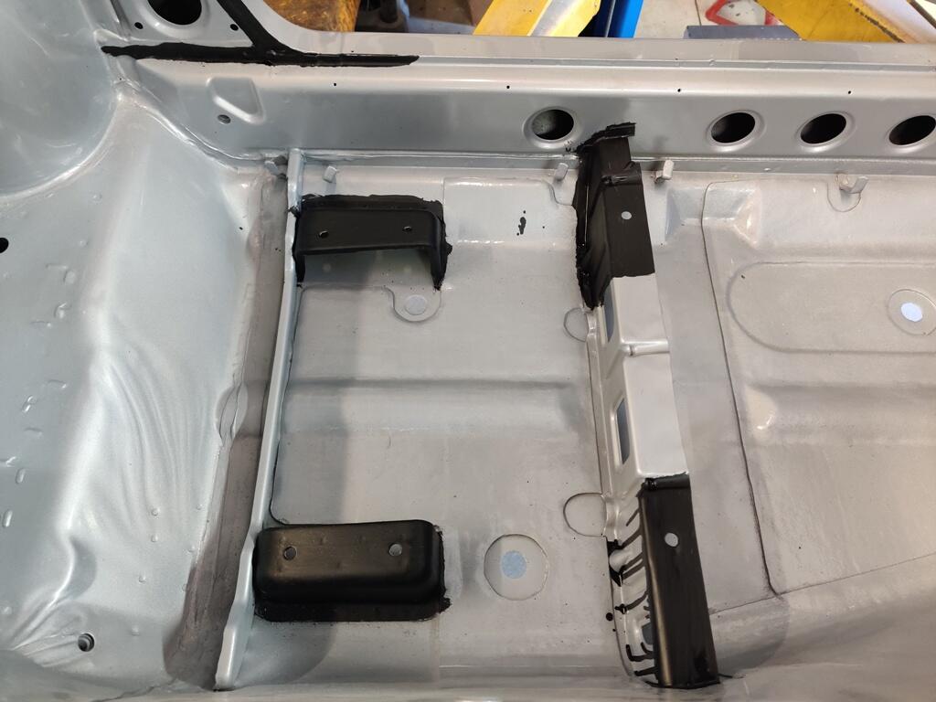
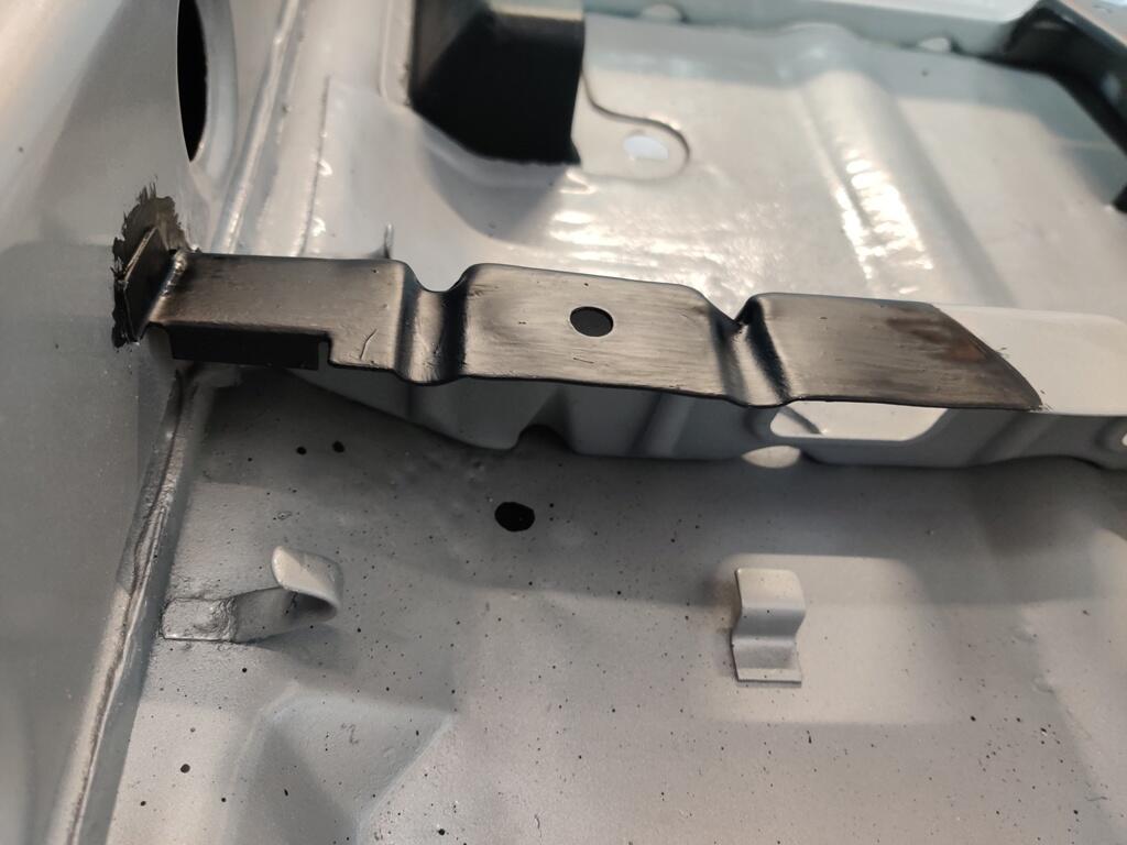
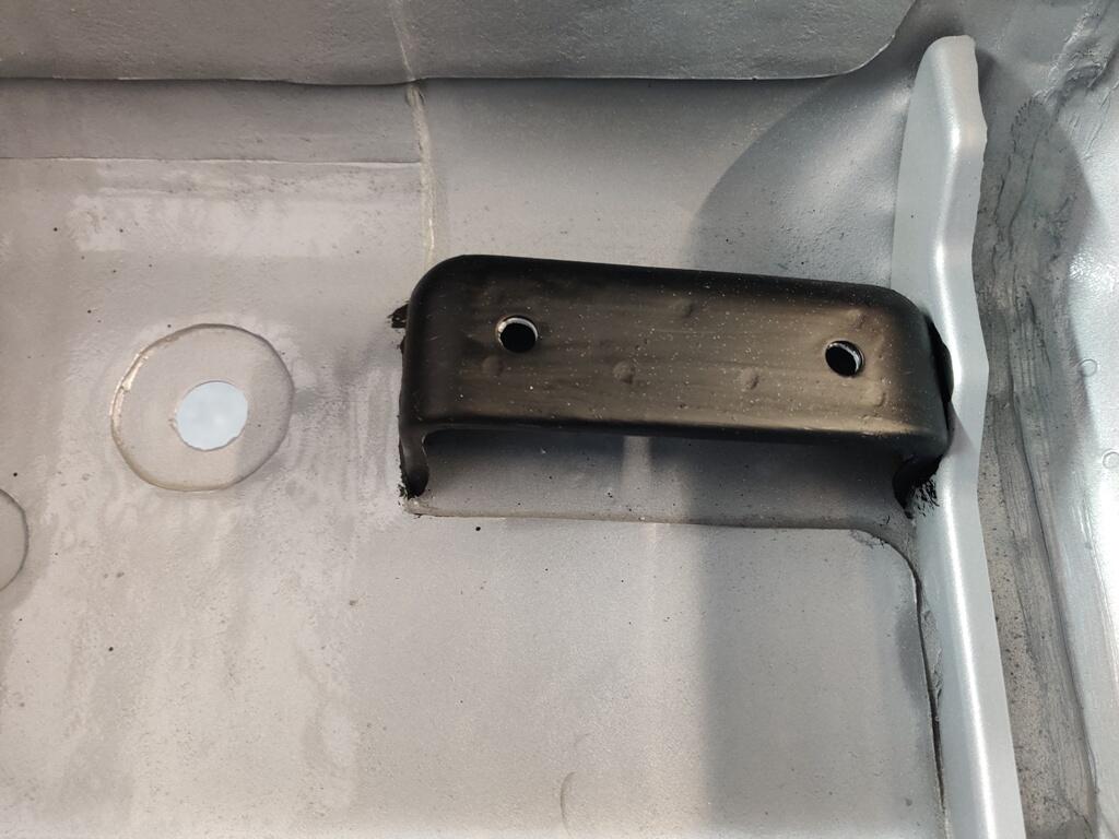
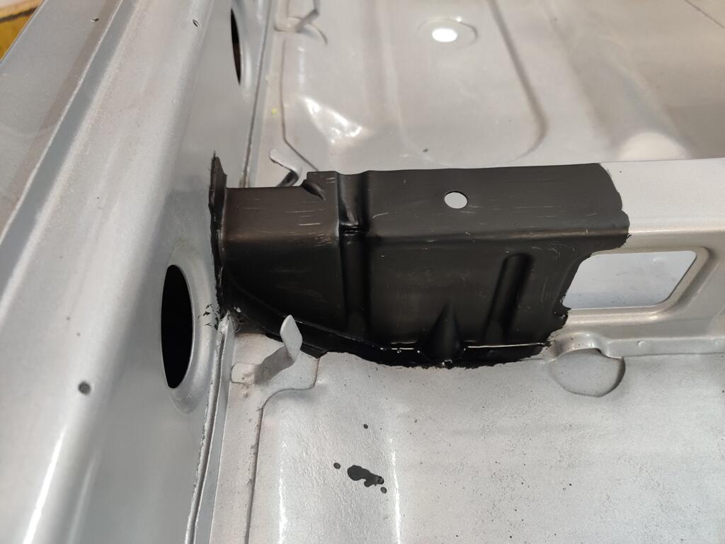
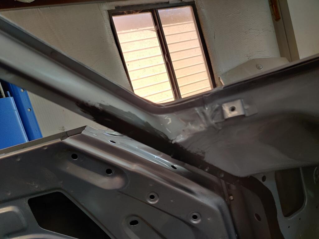
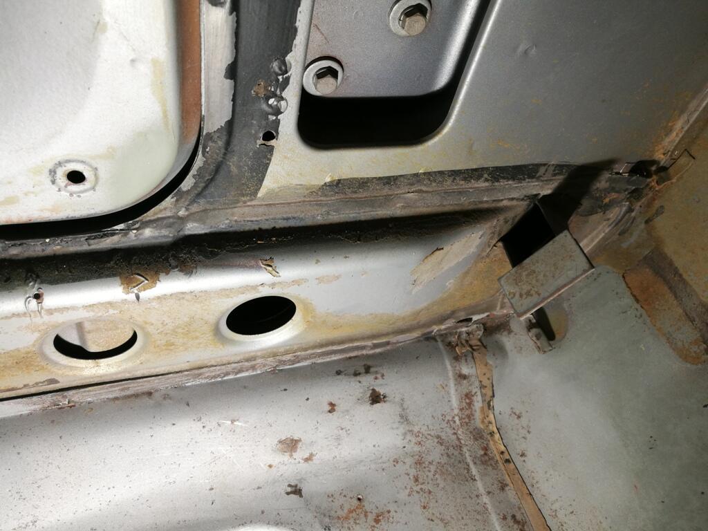
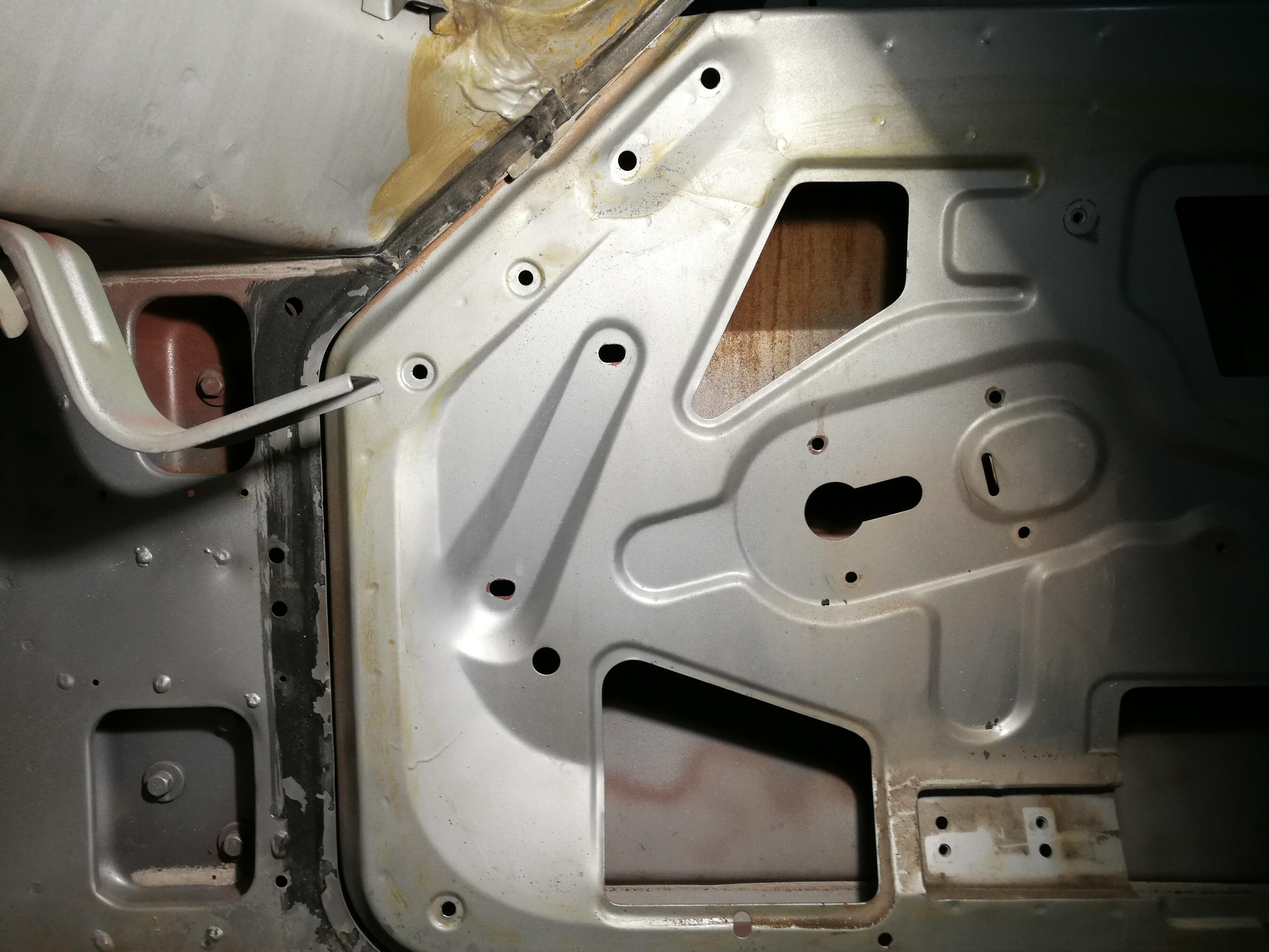
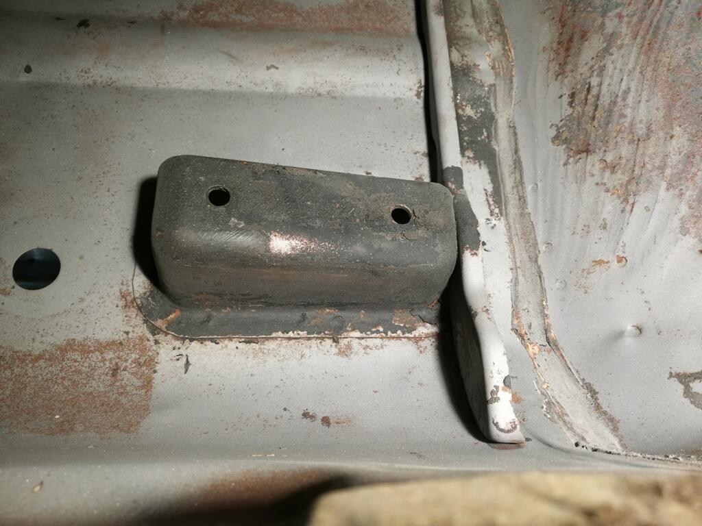
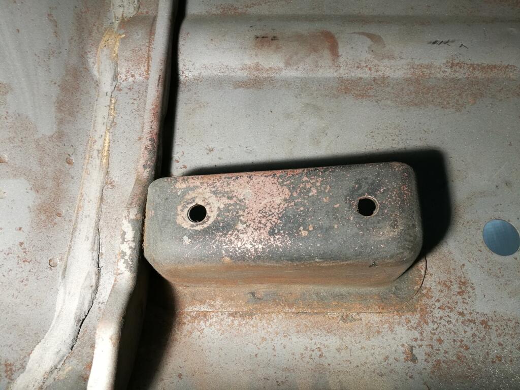
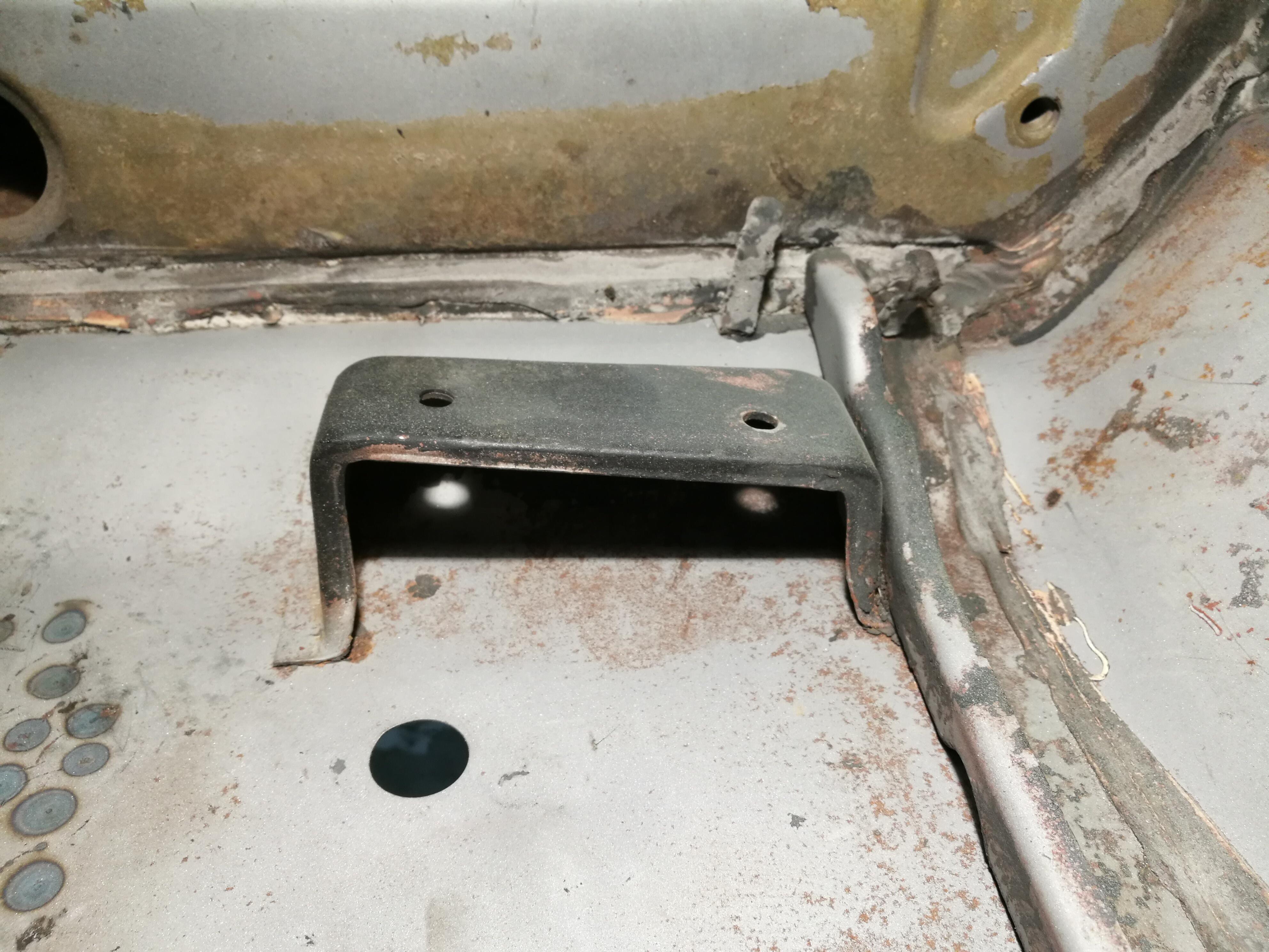
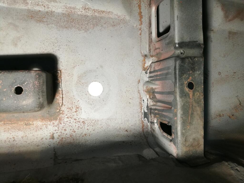
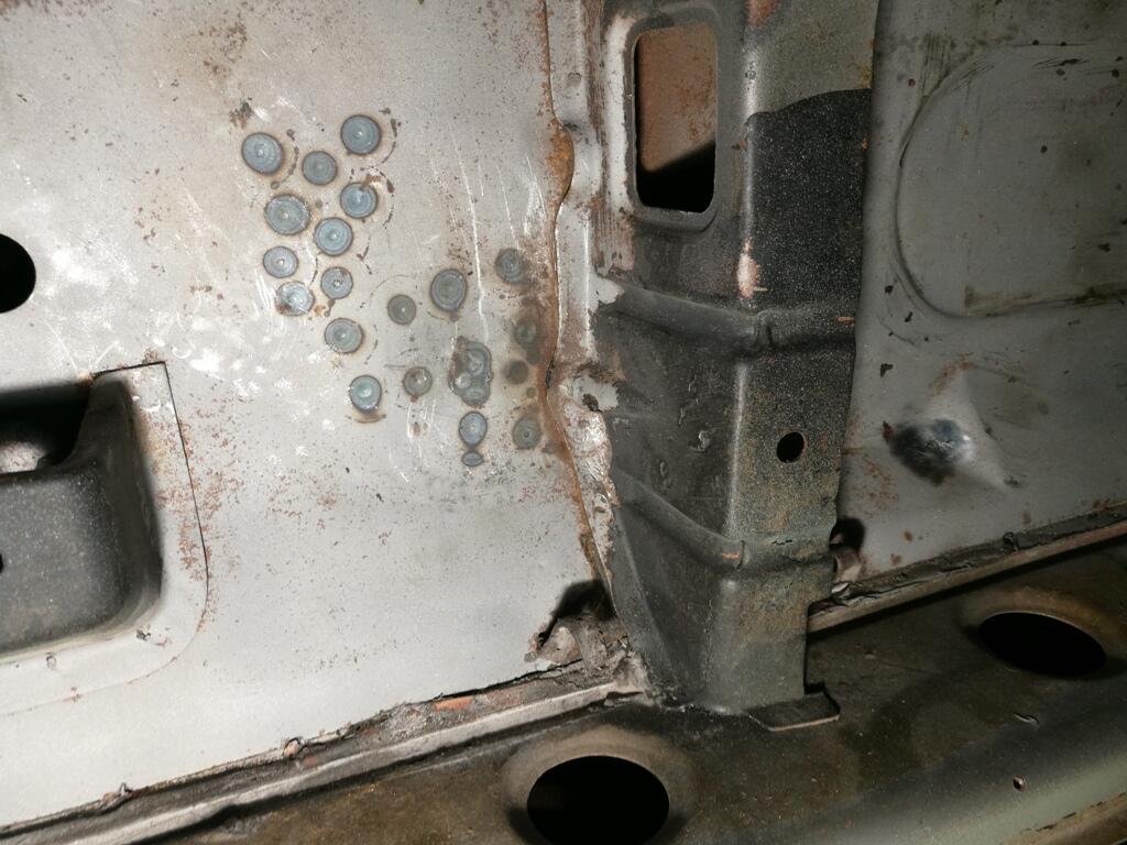
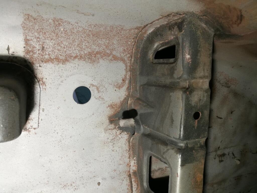
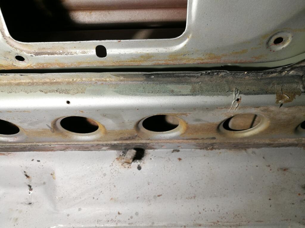
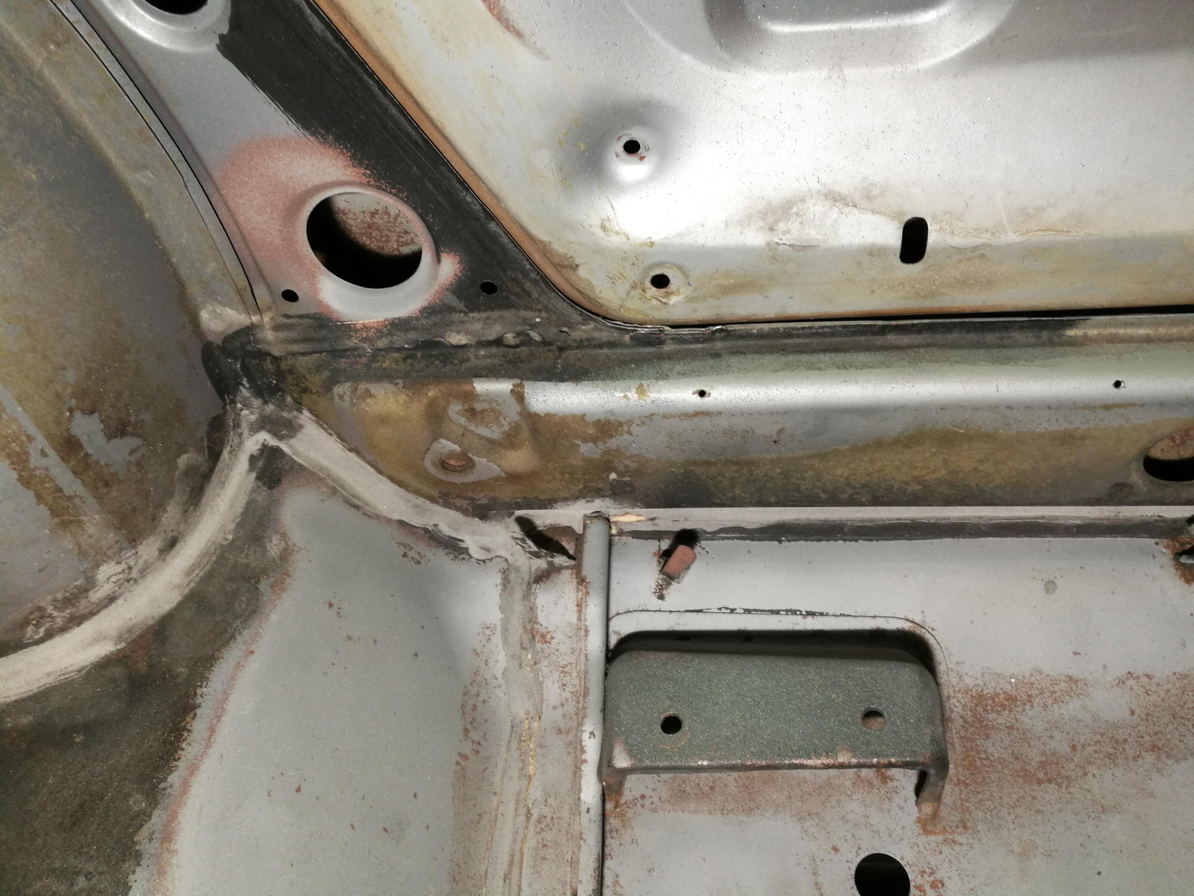
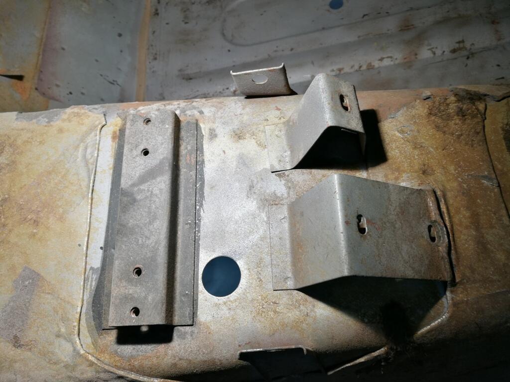
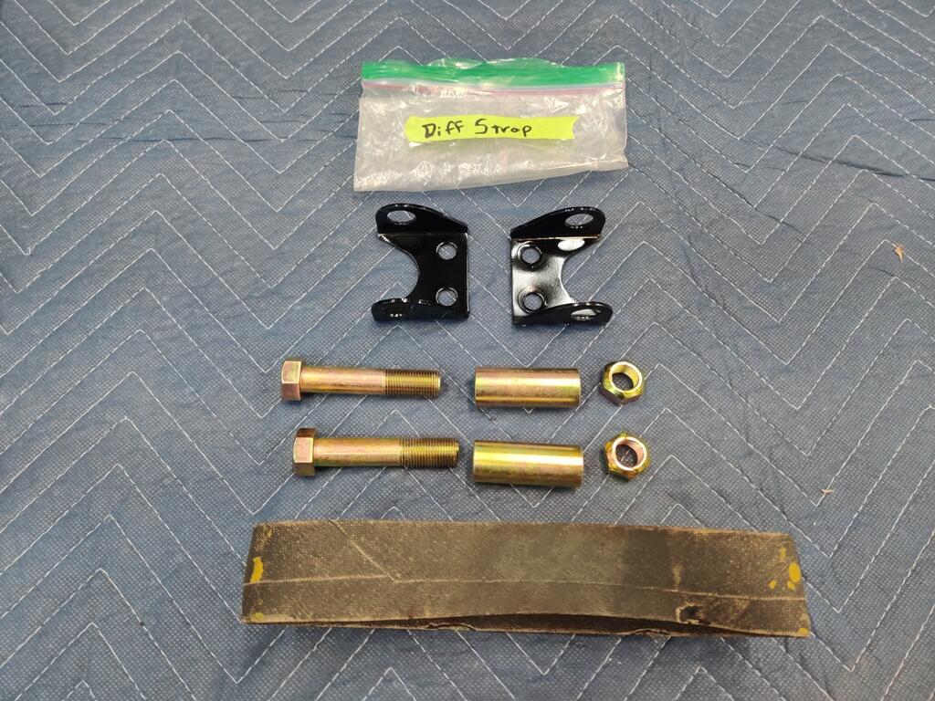
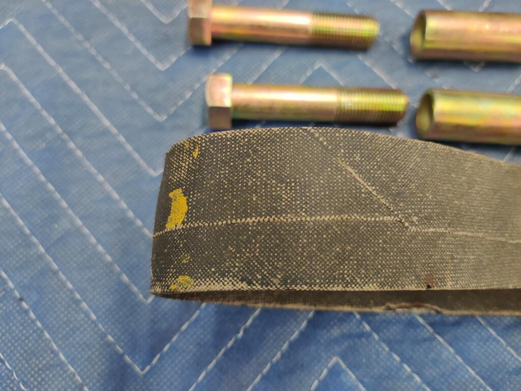
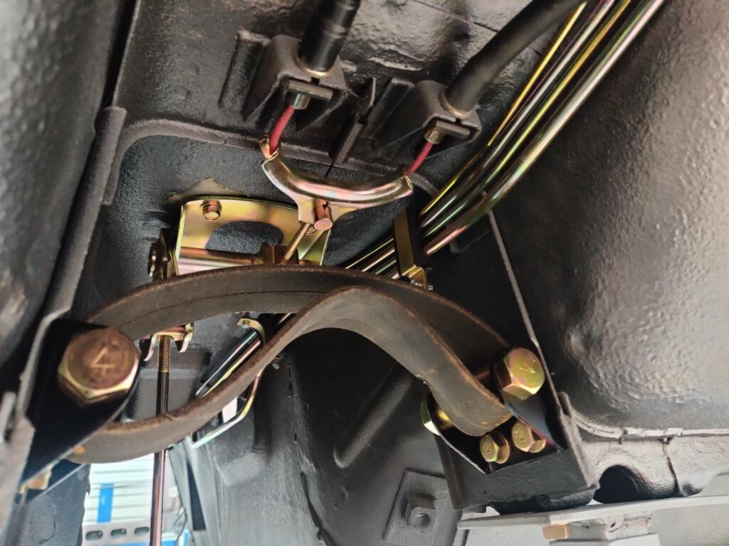
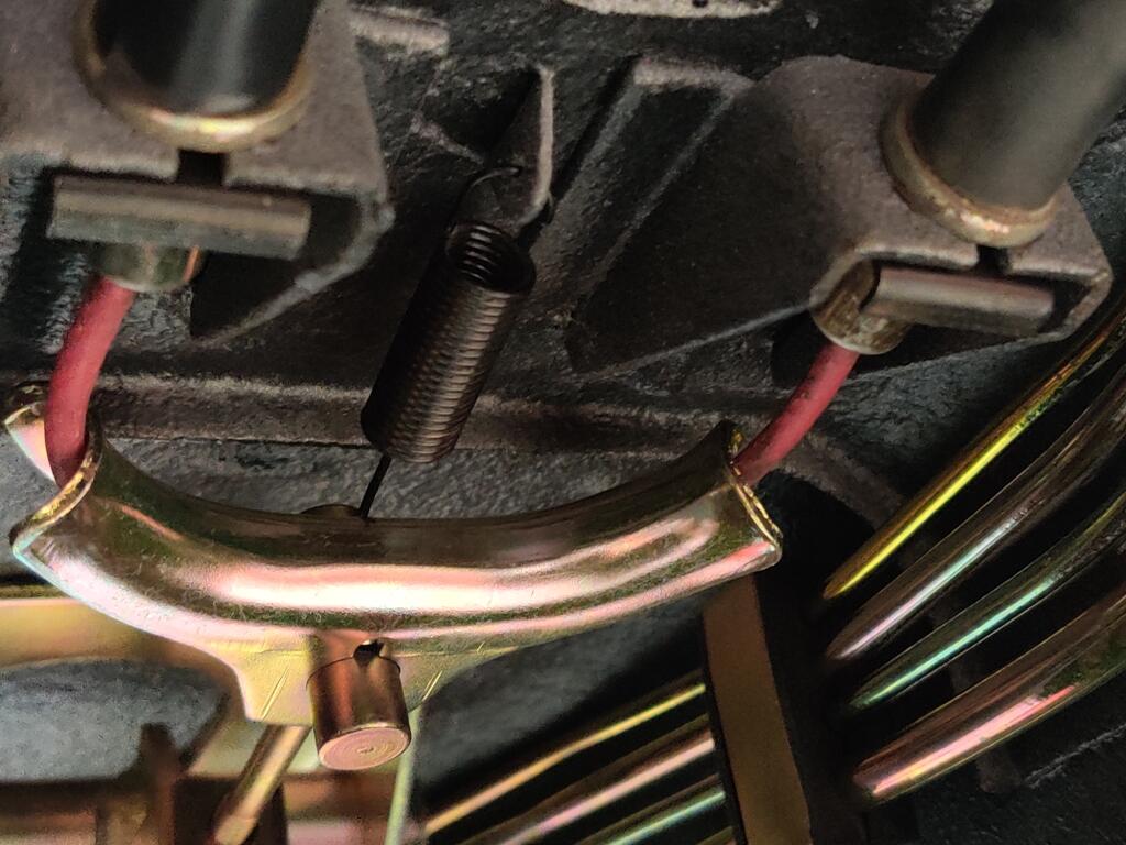
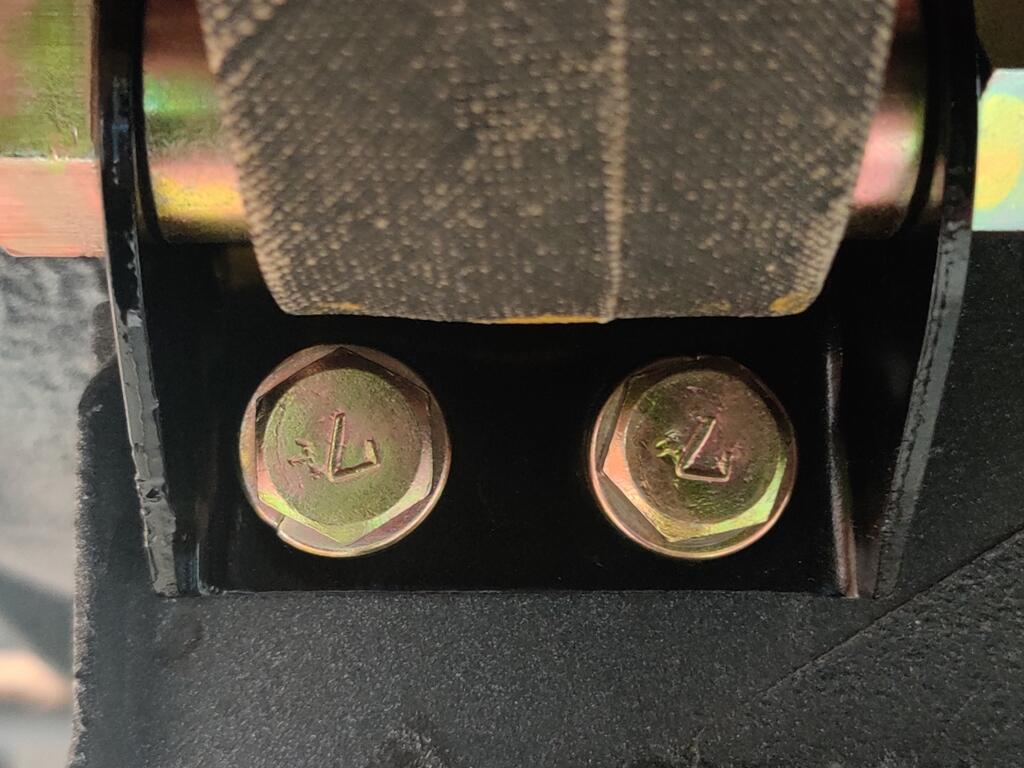
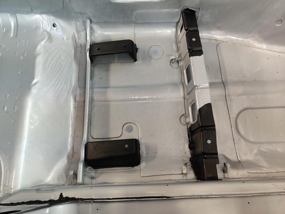
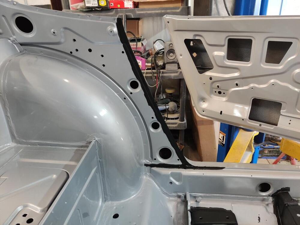
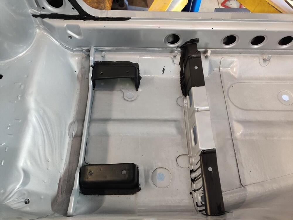
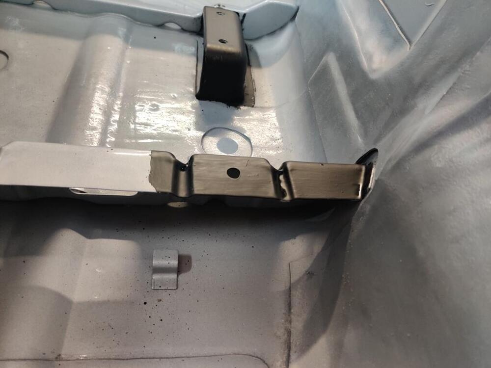
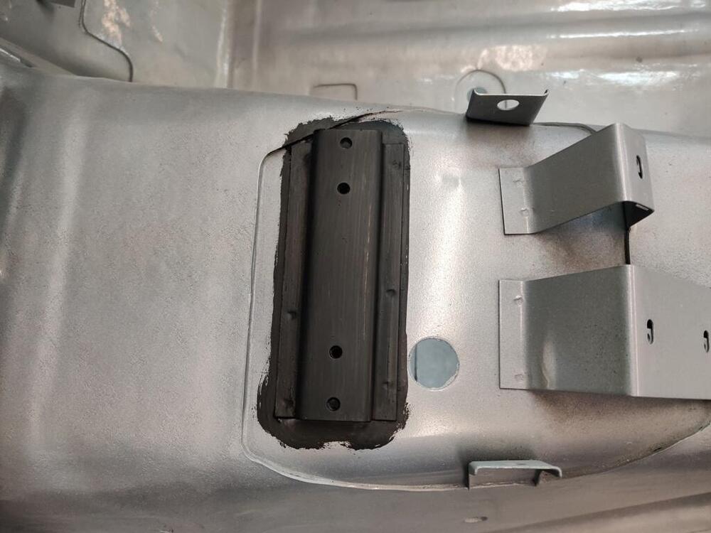
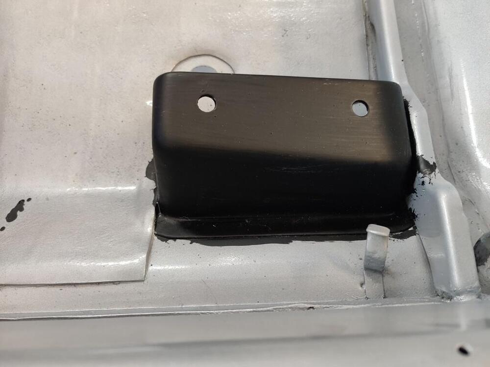
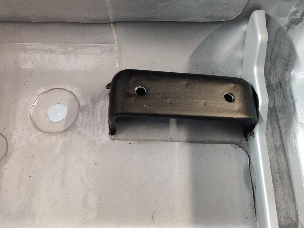
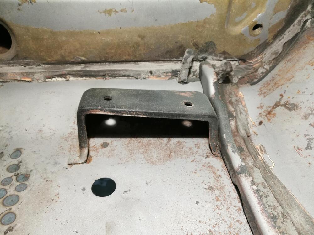
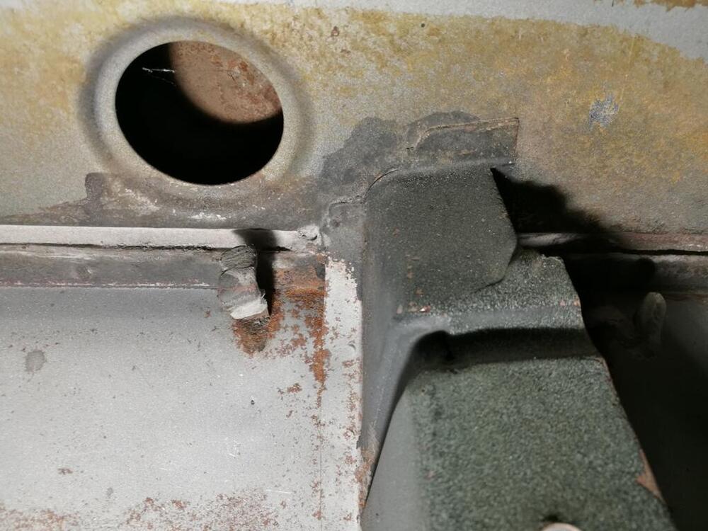
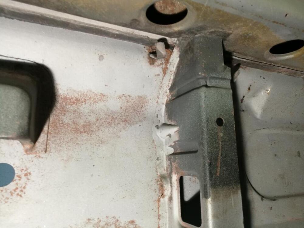
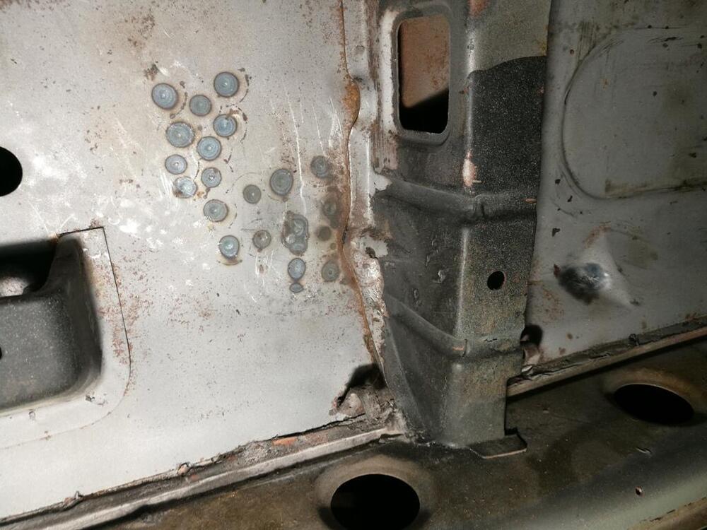
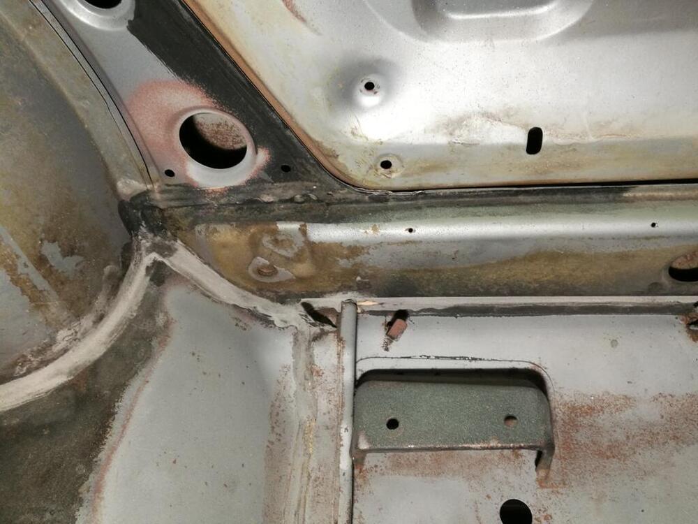
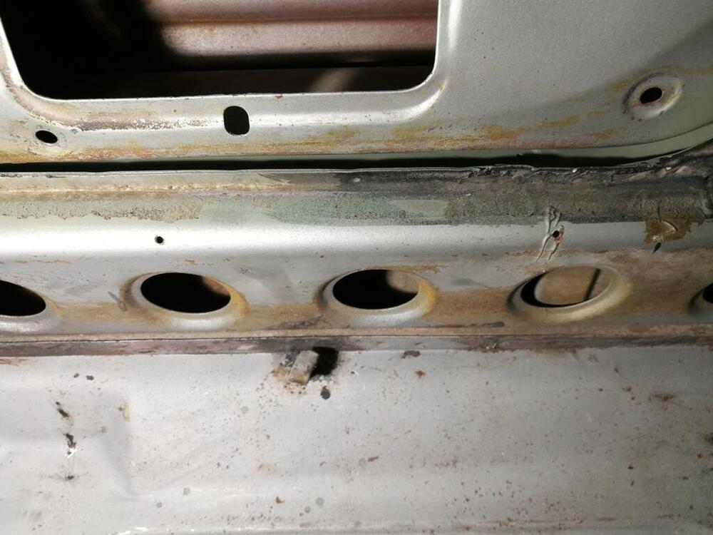
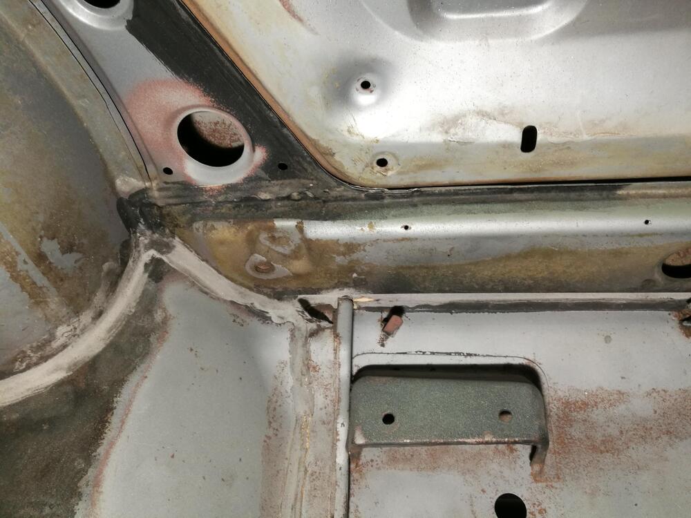
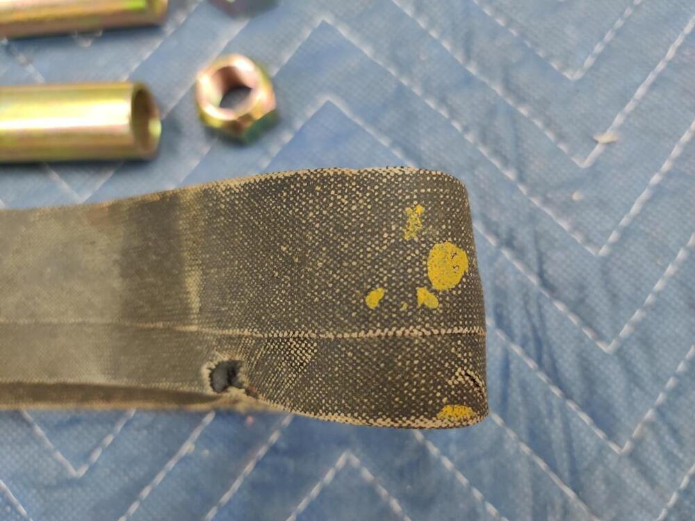
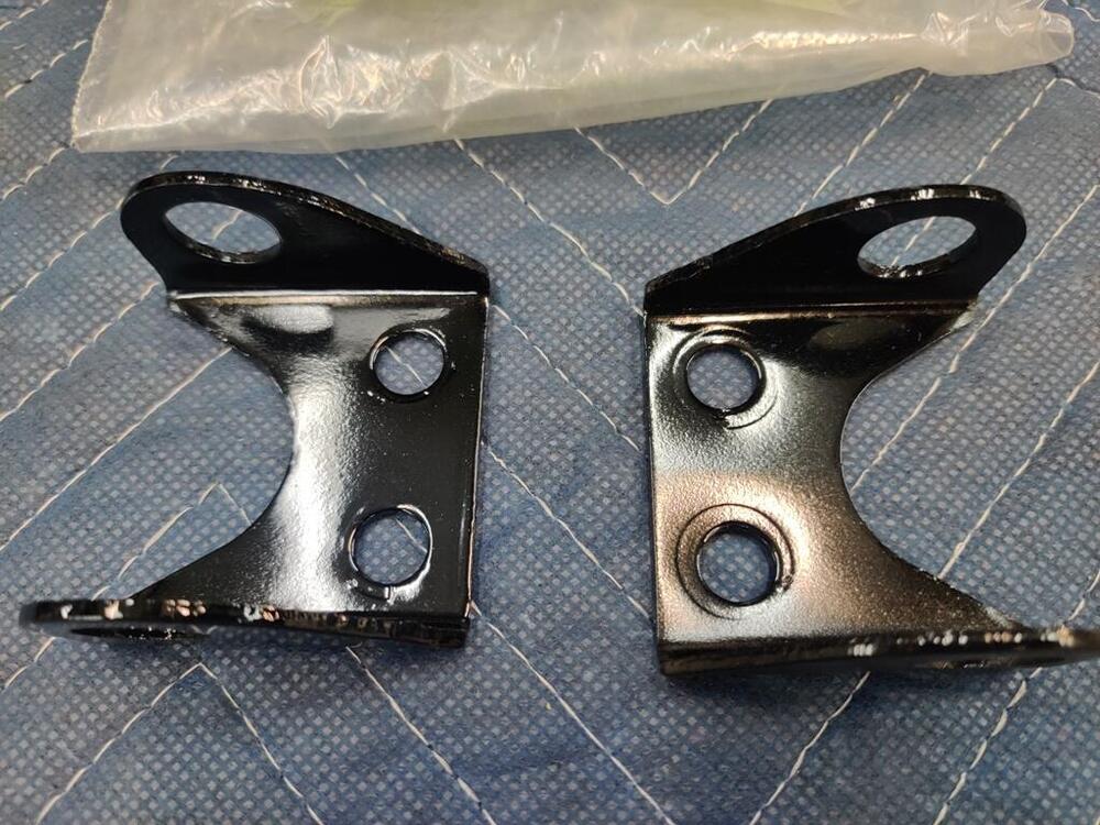
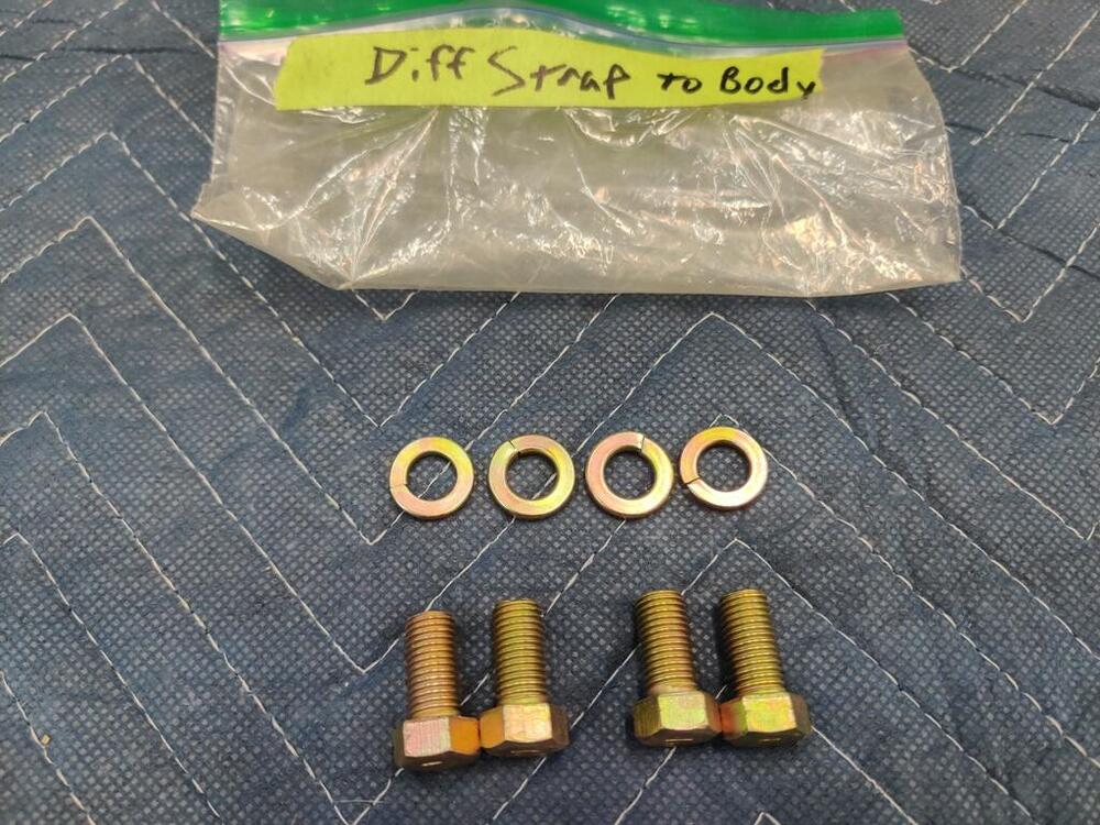
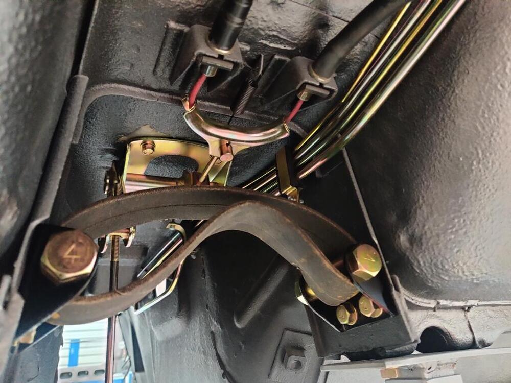
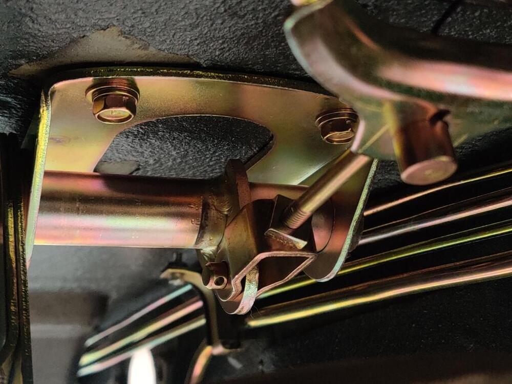
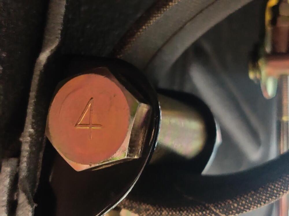
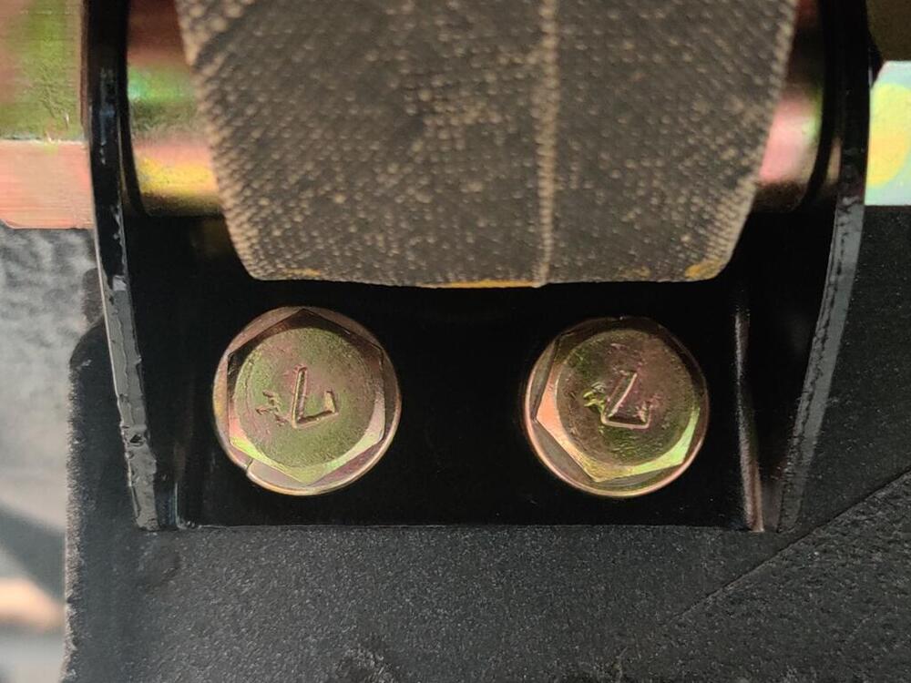
Thanks Steve. I will check those out. Tonight, I put the differential strap in. I reused the original differential arrestor strap. It is in decent shape - it even has original yellow paint dabs on it. One of the things that really excited me about this car was that it spent all of its time prior to my ownership in AZ/CO. The restored hardware is so nice - not pitted from rusting. As these parts go back on the car, some pictures capture the resulting "art":


-
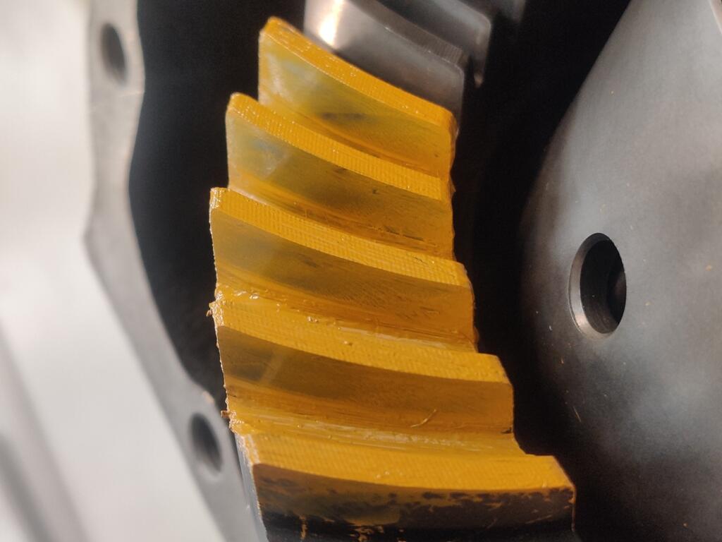
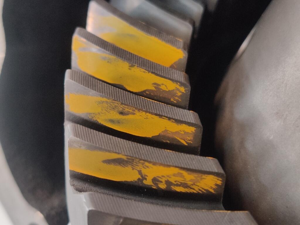
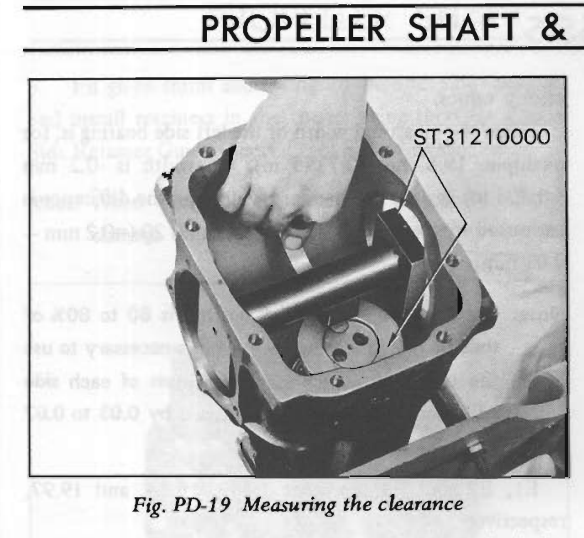
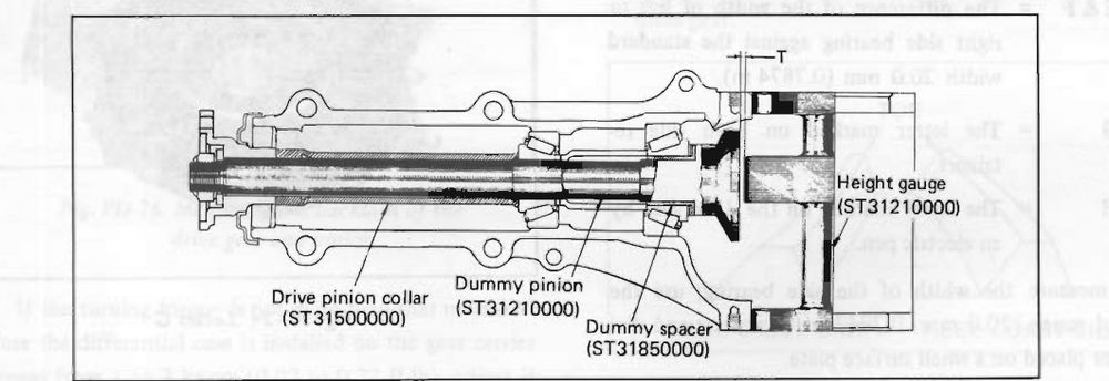
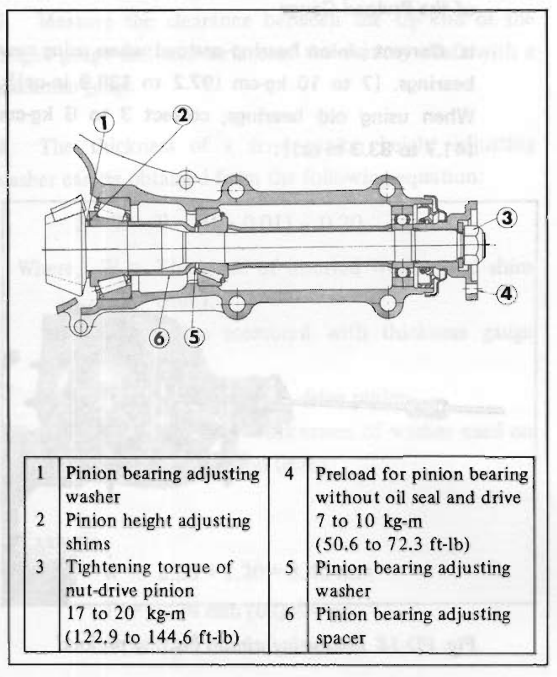
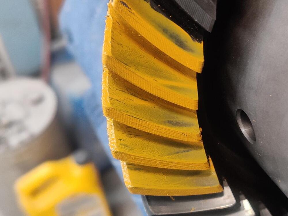
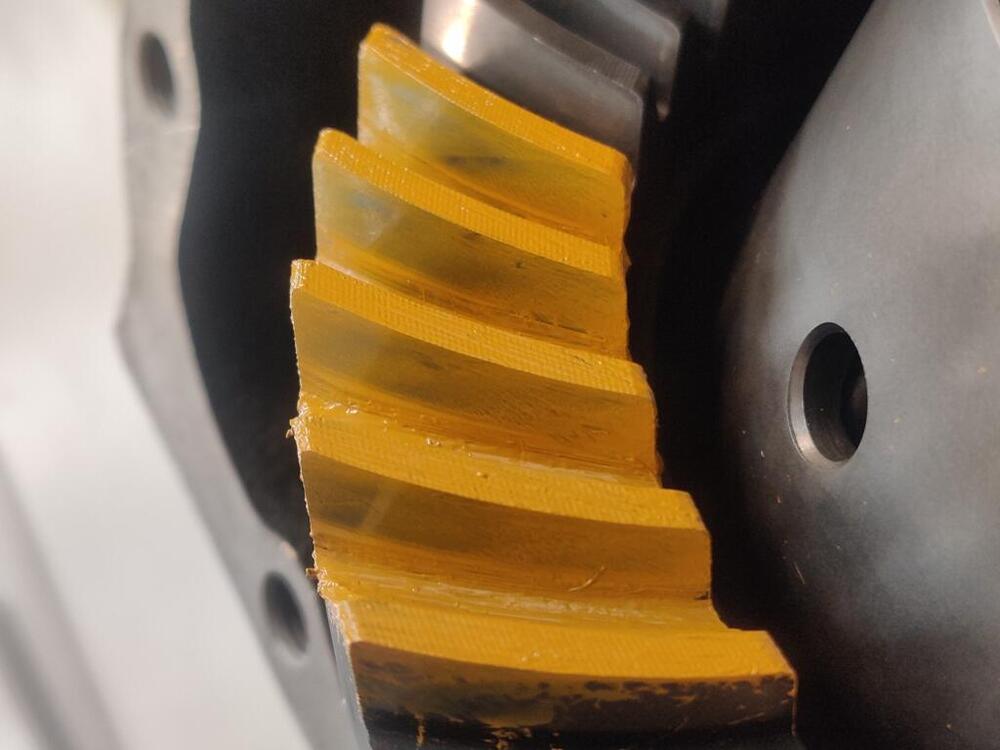
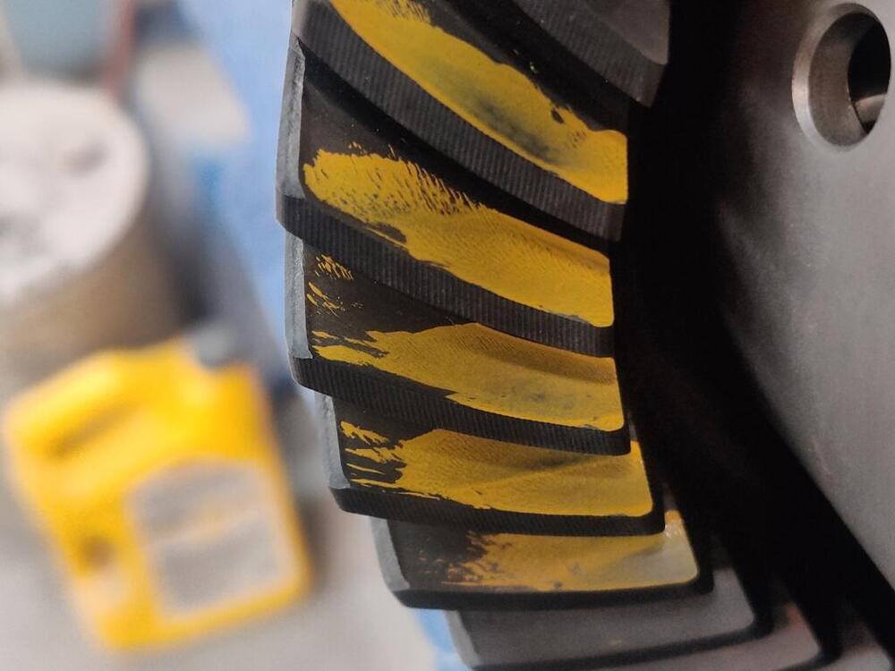
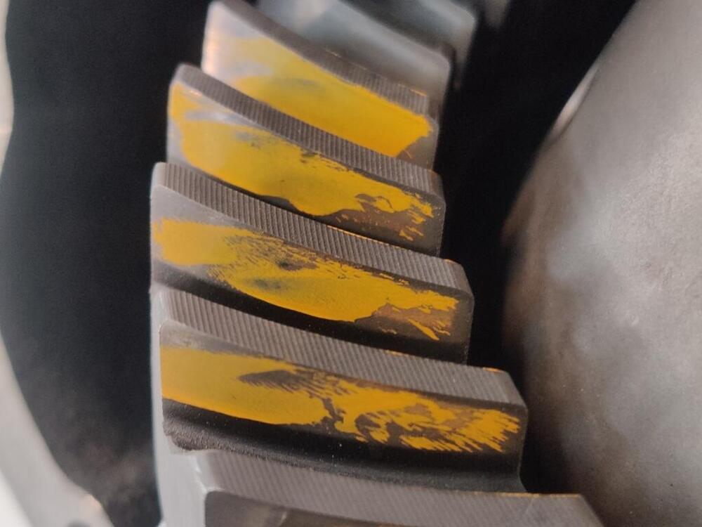
Picture 1 and 2 is using the standard method. Pictures 3 and 4 is just my idea to see if it is any more clear to see the contact areas. The pattern can be hard to see clearly. For what it is worth... here are pictures of the tools for setting pinion gear (height): There is a fake pinion shaft and a bar with square ends. The plan at this point includes removing pretty much everything and pulling the bearings off of the pinion to get to the washer that is #1 in this picture: There were no shims (#2 in the above picture) on this differential. There was only a washer. I need to measure the thickness of this and then either, add a shim (#2) of the correct thickness, or replace the washer (#1) with a thicker one. On Subaru websites, I see only spacers (#1) available: https://www.subarupartwholesale.com/a/Subaru__STI/49247923__6023356/DIFFERENTIAL-INDIVIDUAL/G11-195-03.html Nissan websites show both the spacers and shims as discontinued.
-
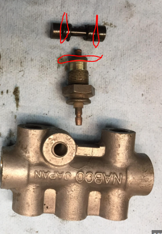
Nice collection. Those are the crush washers of course. The o-rings I am wondering about are inside the switch.
-
Ha! Good to know... as I reused the original aluminum crush washers too. I am less worried about those leaking now, given your experience with that. Thanks for sharing. Wonder if there is a way to determine suitable replacements for the o-rings...
-
Tonight I backed the pinion nut off and reset torque to the low end of the specification. While I had done 135 ft lbs before, I did 124 point something this time, just a couple of ft-lbs above the 122.9 minimum spec. Interestingly, the inch-lbs of turning torque dropped from 14 to 10, which is much closer to the upper end of the turning torque specification. Keep in mind that I measured this with the pinion seal in place, which is not how the factory manual calls for that to be done. You are supposed to check the turning torque without the pinion seal installed in place, and then remove the nut, install the seal and torque the nut again. I think that is kind of ridiculous. So, I am willing to gamble that the 10 inch-lbs I am seeing with the seal installed is just fine. After doing that, I reinstalled the carrier and side retainers, and check the gear wipe pattern: front side of ring gear (first pic), back side of ring gear (second pic): The first pair of pics shows where I applied the yellow paint directly to the ring gear. I went back and forth through that with the pinion gear to get the first set of impressions. After that, I kept rotating the pinion gear around until the paint that transferred from the ring gear to the pinion gear made another set of marks on "clean" teeth on the ring gear. The transfer of paint from the pinion to the clean teeth on the ring gear is captured in the second pair of pics. What I see is "toe" contact on the coast side of the ring gear (first pic). And I see heel contact on the drive side of the ring gear (second pic). According to the shop manual, I will need to "increase the thickness of the drive pinion adjusting shim and washer so that the drive pinion is moved to the drive gear". As I see it currently, I'm going to have to remove the carrier from the case (which requires removing one of the ring gear bolts in order for it to clear the case), and to remove the pinion gear, and bearings so that I can add a shim of unknown thickness to shift the pinion gear towards the ring gear. If I guess wrong on the shim I install, then I won't know until I assemble everything again. If wrong, it all has to come apart again. I guess again... rinse repeat... I think I see hours of time and frustration for this little project in my future. Anyone have factory tools for me to use to get this thing set up properly without a bunch of hassle? Or ideas for how to save that time and hassle?
-
I think you are right - it is a brake light switch (not proportioning valve). That is the one that came with my car. I disassembled it, sent off a few internal and external parts to get them plated, and glass bead blasted the body. I glass beaded it at 90 psi to clean... and then another pass at about 50 psi to give it a smoother finish. Interesting. Maybe I will do the same for a measure of safety. Having brake fluid squirt all over the engine compartment and the damage that would cause... 🥶 I feel a little uneasy about reusing the original o-rings, but that is what I did. I don't know how to source suitable replacements that would meet the performance criteria?