inline6
 Subscriber
-
Joined
-
Last visited
Everything posted by inline6
-
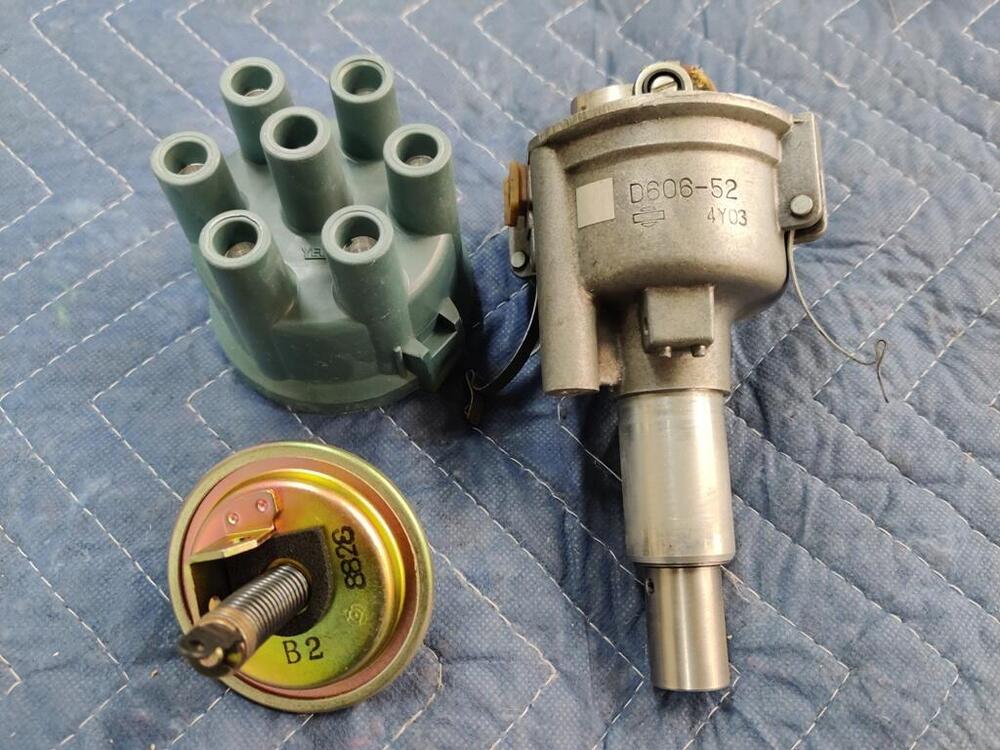
 A while back, I heard that the original distributer cap was grey. Going off of that and a poor quality picture on BAT, I was able to find a grey YEC branded cap, but didn't know if it was close to the correct color. Today, I found a picture of an original Hitachi distributor cap: Putting that here for reference for others.
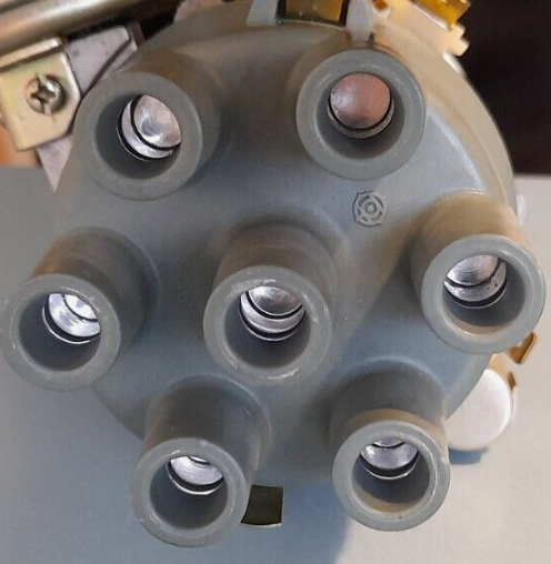
-
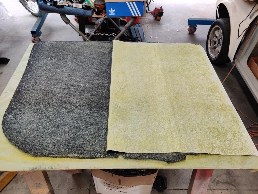
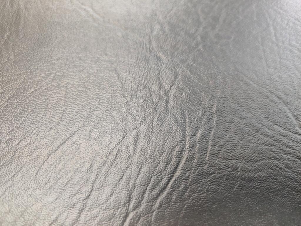
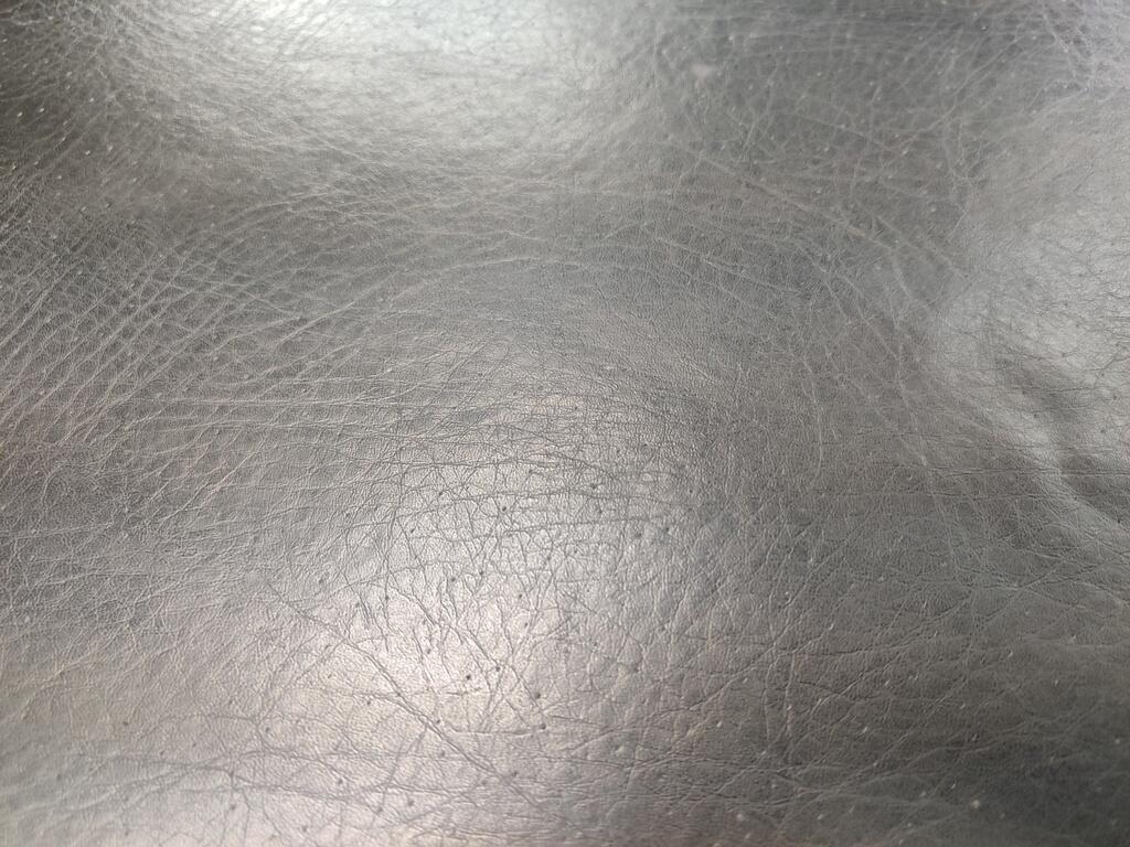
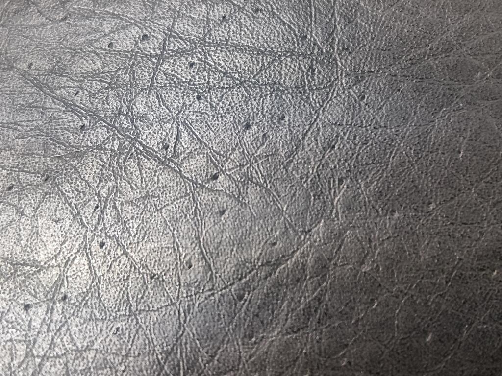
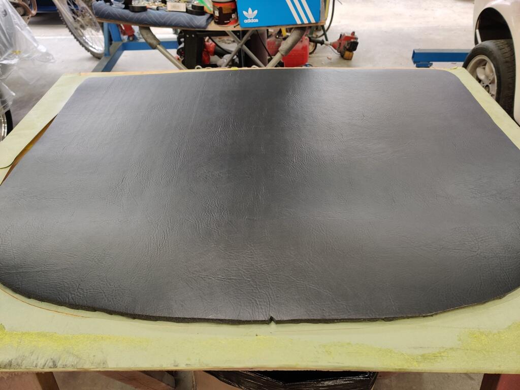
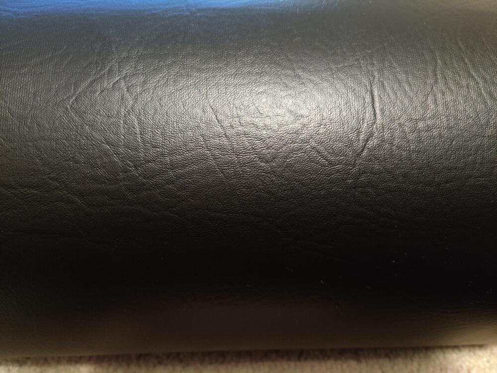
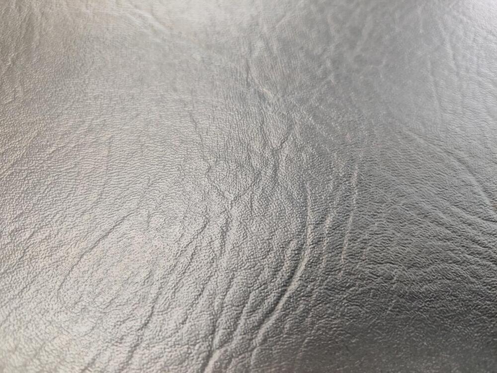
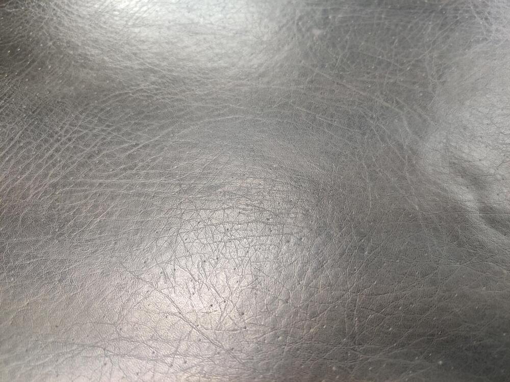
The vinyl is "Ottertex", and it is sold in a few places. I got mine from fabricwholesaledirect.com. It is 54" wide and sold by the running yard. I bought three running yards because it was so inexpensive - it was only $9.99 a running yard. To ship it, they folded over and over into a square. When I got it, I immediately unpacked it. The folds and creases were visible even after I spread it out on a floor. Then, I rolled it up onto and existing roll of foam material that I bought previously. This was a few days ago. Yesterday, when I unrolled it from the foam, the fold lines were still visible. So, before gluing it to the foam, I used a steamer to relax the vinyl in those areas. It helped, but they were still visible. I was concerned that they would be visible after gluing. I was glad to see and very relieved that they disappeared when I glued it to the foam. Hi res photo: I think I am going to switch to this vinyl for the A-pillars and windshield header because it looks more like the original than the vinyl I bought previously.
-
I spent many hours searching the internet and looking at vinyls, and I am pleased to have found a vinyl that looks similar to the original one for the headliner. I wasn't able to salvage my original vinyl, however, I think the headliner I made today looks quite similar. Original: As I said before, unfortunately, I wasn't able to glue the old vinyl to new foam without getting a lot of wrinkles: Unlike the old vinyl, the new vinyl has a cloth backing which makes it lay flatter and makes it stronger. I sprayed the contact adhesive out of a gun similar to a paint gun. The gun was purchased for doing this and it worked very well. The new vinyl: The finished product: While I had adhesive in the gun, I installed the new fire wall pads. I will put up some pictures of those being installed tomorrow.


-
Good to know. I am concerned about the area where I welded on my gas tank. I chose to remove a "drain" that was added by the shop that cleaned and coated the inside of my tank. Though I believe I got it air tight again, I fear it may develop a leak in that corner of the tank. It is good to be aware of options.
-
Much of that looks similar to my process. My sanding utilizes those same grits. What is most different is the second pad, and DA. I use a rotary buffer for all three buffing stages. I use Meguiars Diamond cut M8532 with a lambswool pad. Then I switch to M8332 with a Meguiars yellow foam pad. At the end of this stage, the paint typically looks good enough to call it "finished" from just a few feet away, but there are typically some very light "swirl" marks if you look at it in the right light, or if you wait a week and look at it in direct sunlight. I don't see "light scratch" imperfections going in various directions at this stage. And for the final stage, I use Meguiars number 7 on a Meguiars black foam finishing pad. I have found this stuff to be excellent at removing the last evidence of any kind of buffing or swirl marks. I also use it for final polishing of plastic parts like light tail lights and the clear dashboard instrument lenses. I didn't wet sand and buff my current restoration project, but I have used the above process many times and the resulting finish is without flaws.
-
Thanks. Looks like currently $625 + $165 shipping.
-
Hmmm. Are those in the clear coat only, or showing up from underneath the color coat and transferring to the top surface? What is your process starting with fresh clear coat that is ready to sand? Sanding with different grits? Wet sanding only? Buffing with different compounds? Changing pad type as you change compounds?
-
Comes from overseas, right? How much including delivery?
-
View Advert 16 X 7 zero offset Panasport Wheels (two) - great condition I have two of these for sale along with two new old stock center caps. The wheels are in great condition. One of them has a light scrape on the outer edge, which I dressed lightly with a file (pictures of before and after included here). It is about 1/2" or so long. A couple of paint chips here and there. They still have the stickers on them from new. The wheels are boxed up and ready to ship. Price is $450 plus the cost of ground shipping to you. Advertiser inline6 Date 02/08/2024 Price $450 Category Parts for Sale
-
Hmmm. I wonder if it is a permissions thing. I will have a look to see if I can resolve. Evidently, there are no permissions levels that are suitable to allow others to expand the sections. So, I have opened them all up.
-
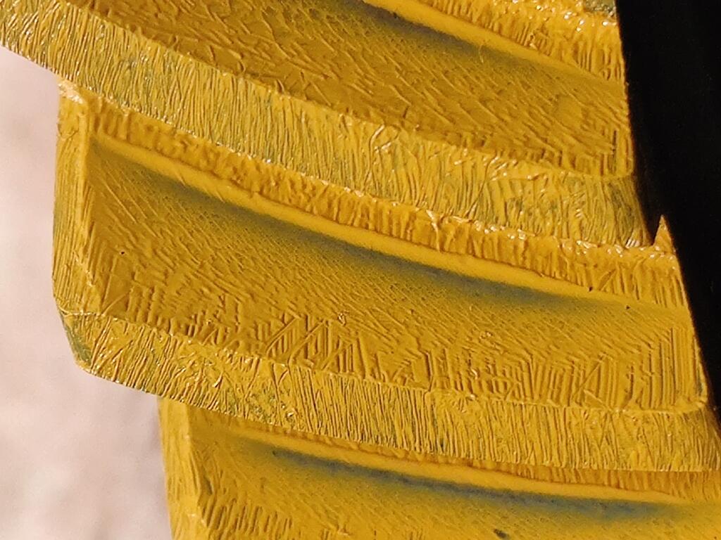
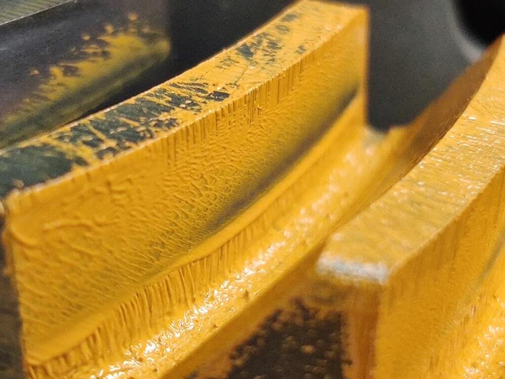
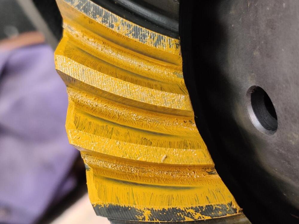
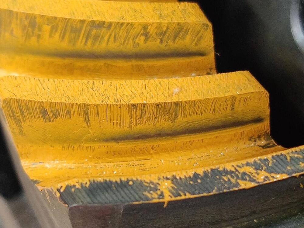
The contact patterns are looking very close to optimal to me. I think I need to experiment with something between .015" and .020" of extra shim thickness to see if I can move the patterns on the drive and coast side to be closer to the same contact area on the tooth. Right now the coast side is a bit more towards the heel and the drive side is a bit too close to the toe. I hope pressing the bearings on and removing them from the pinion gear this many times is not causing any issues.
-
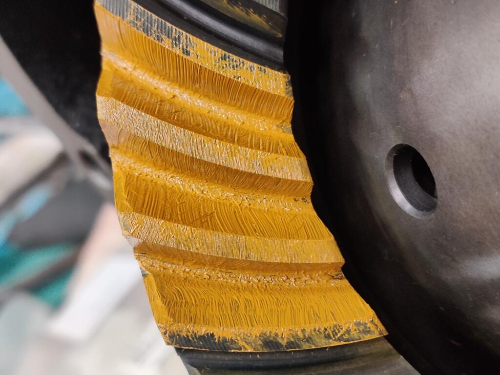
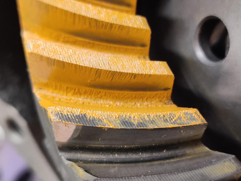
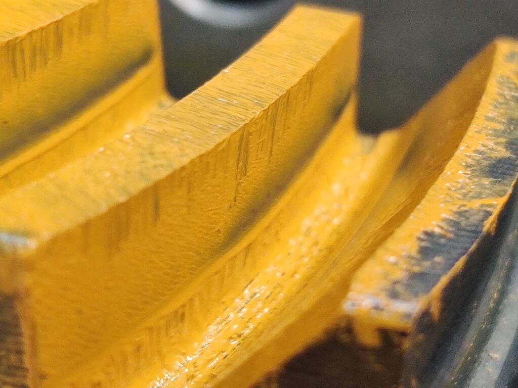
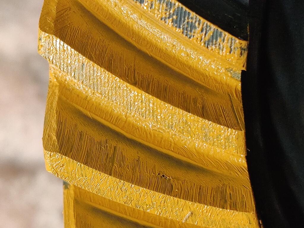
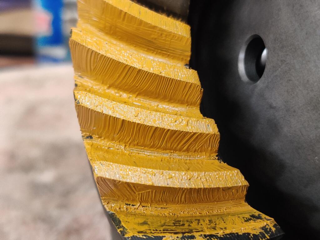
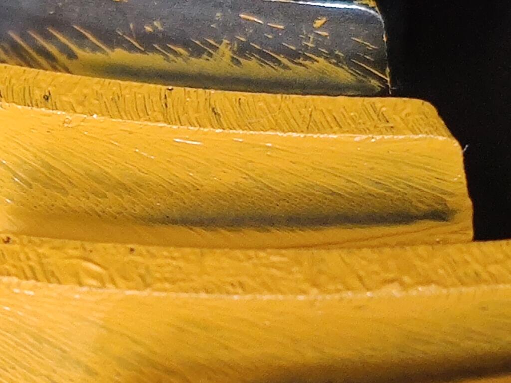
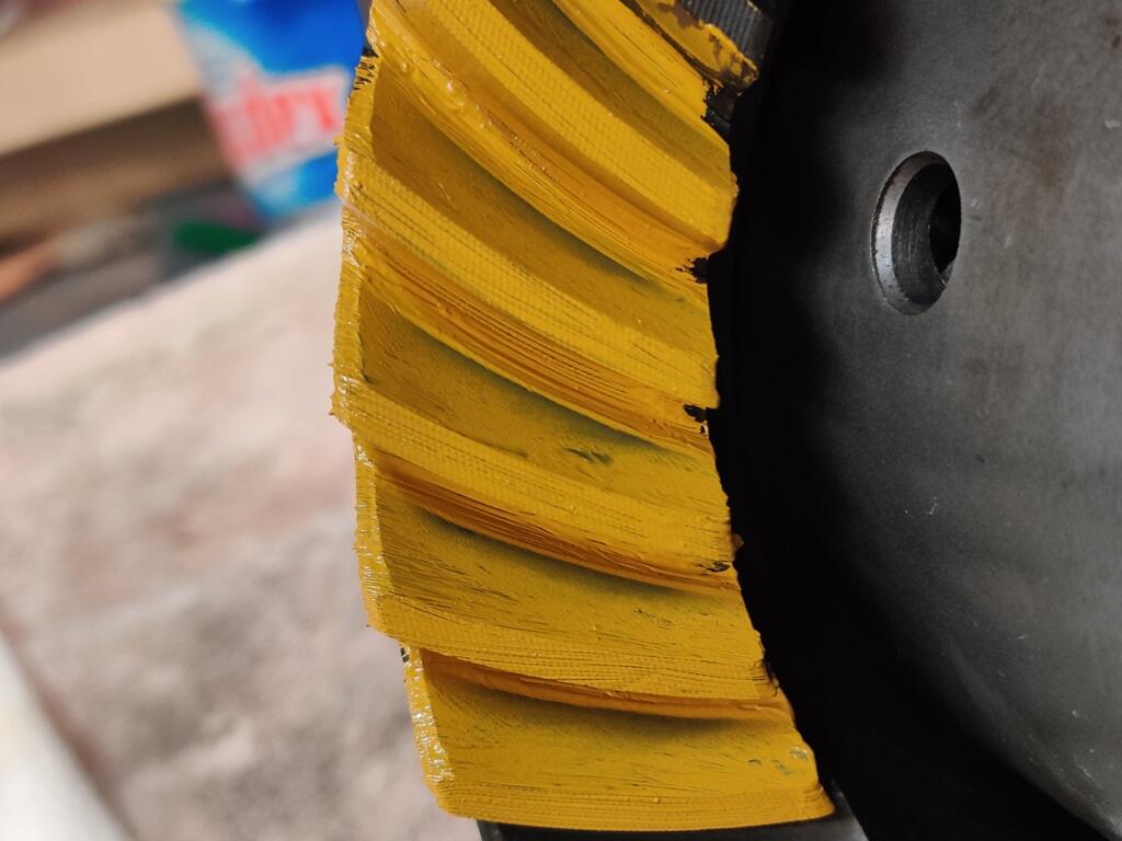
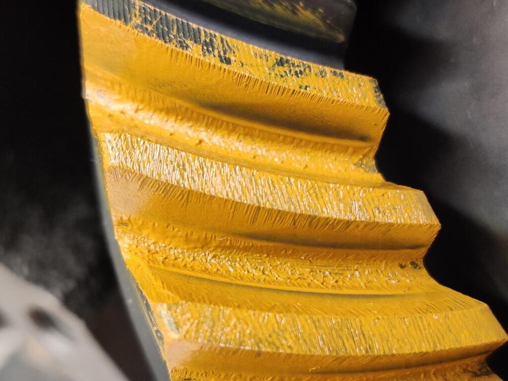
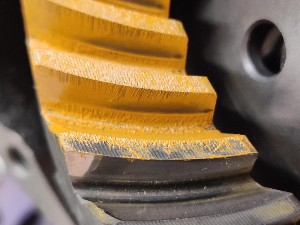
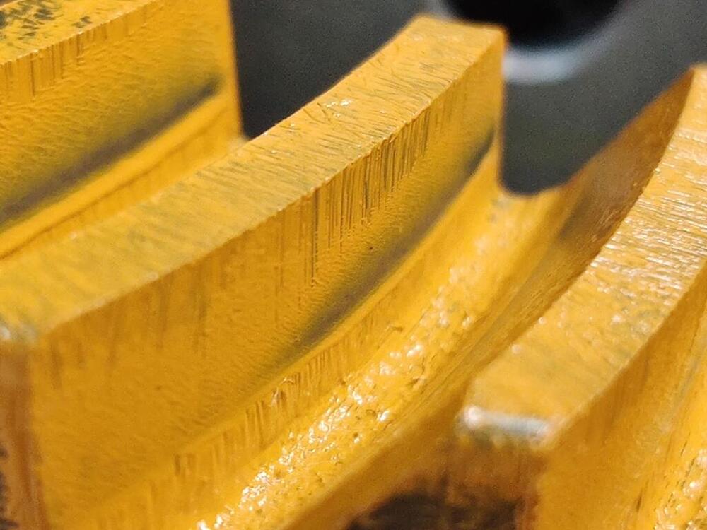
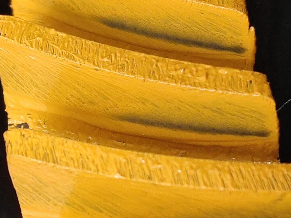
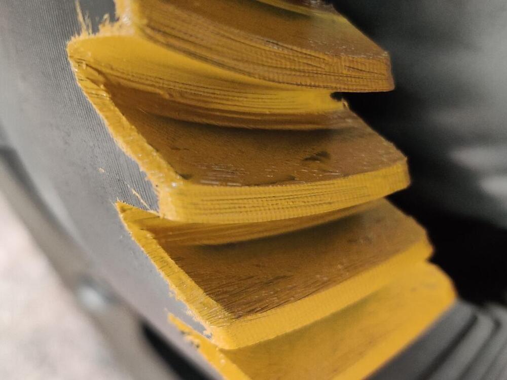
Another round. This time, I only shuffled some side flange shims. I removed the .3 mm from the left side and replaced it with a .2 mm. Then, I swapped out the .4 mm on the right side for a .5 mm. So, the right side has 2 .5 mm instead of a .4 and .5 mm. So, with the OEM shim, + .020" of extra shims and the side flange shims as just described, the back lash was a touch over .006". I put the marking compound on thin again with brush strokes the same as before: One pic showing wipe patterns on both sides of the ring gear teeth: And the rest - note that beyond the obvious displacement of the paint that reveals the tooth surface, the brush strokes are "erased" further out, indicating possible tooth to tooth contact there (or super close proximity) as well.


-
That is the one I got.
-
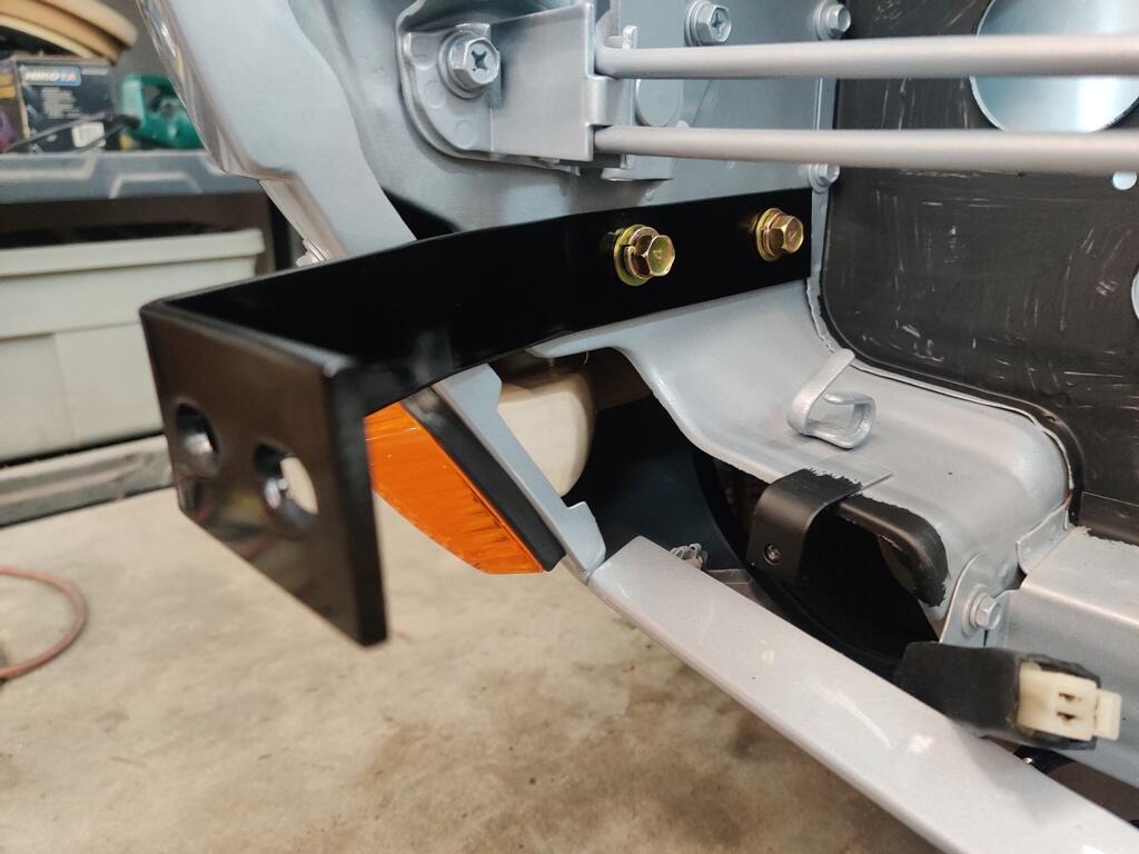
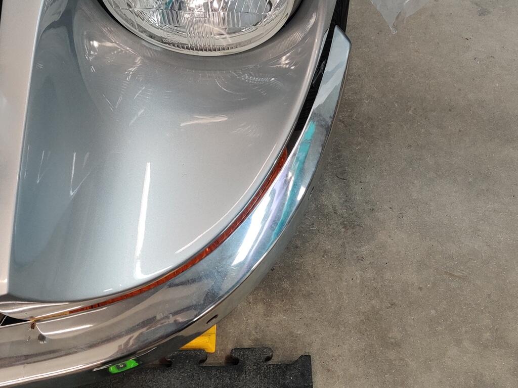
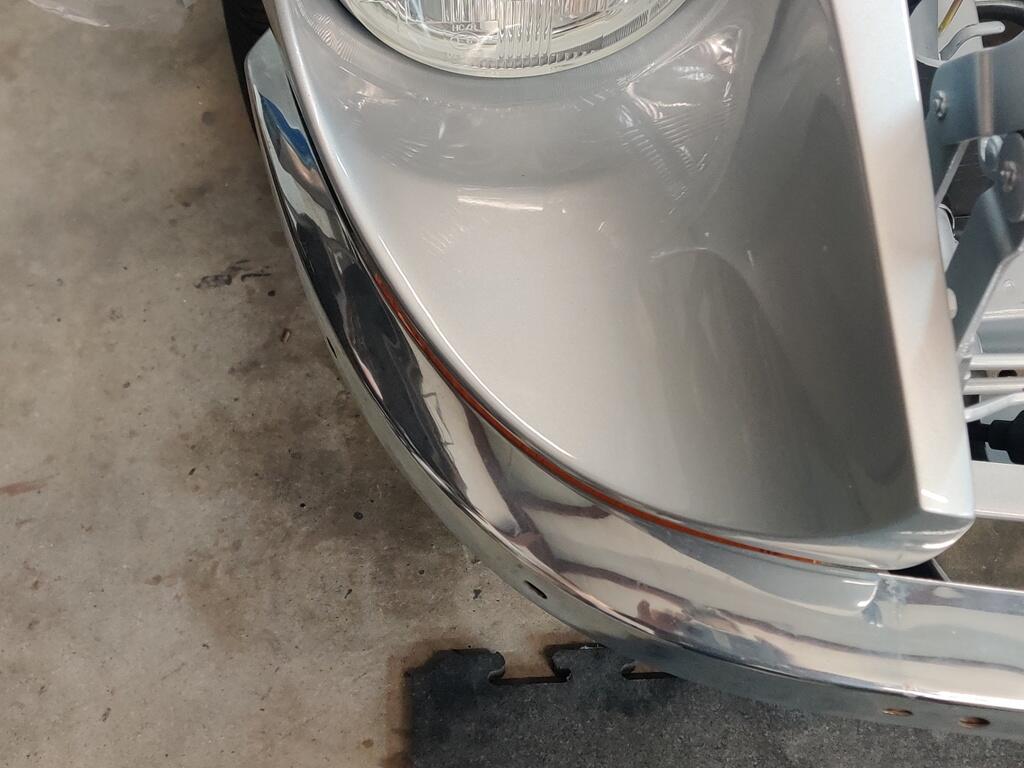
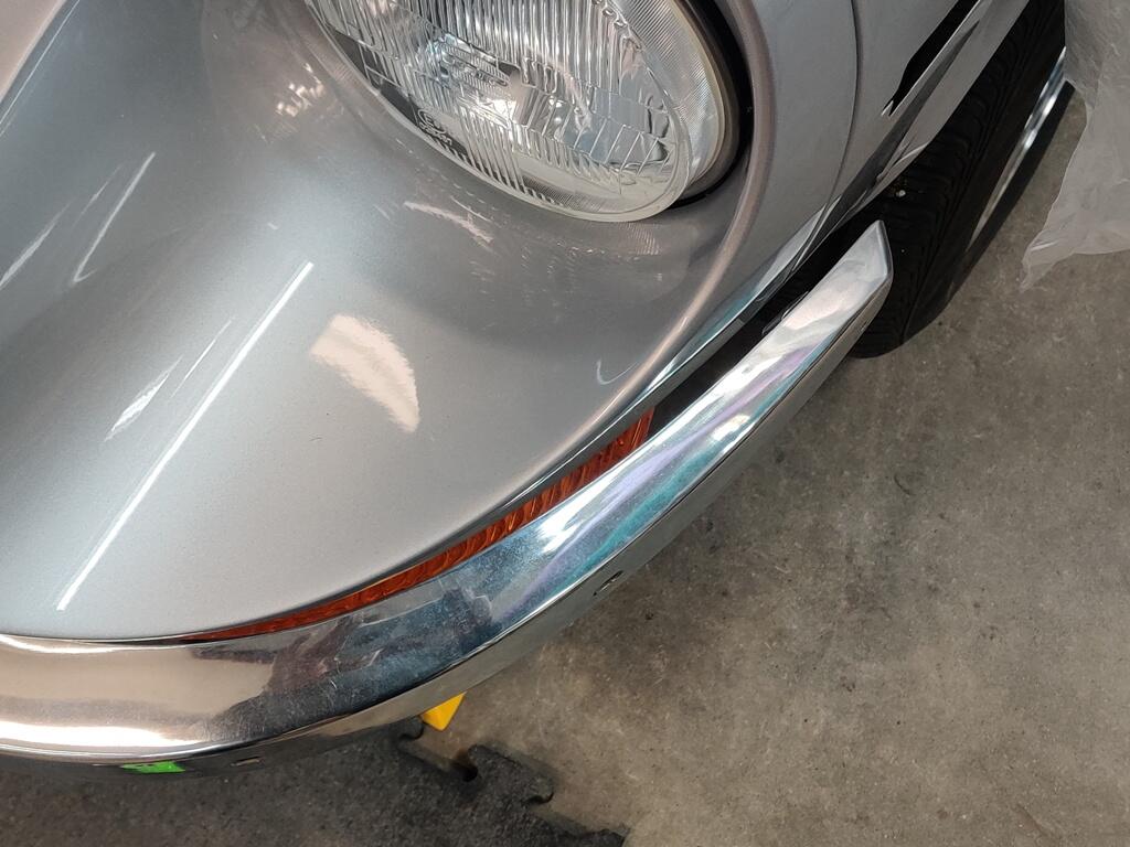
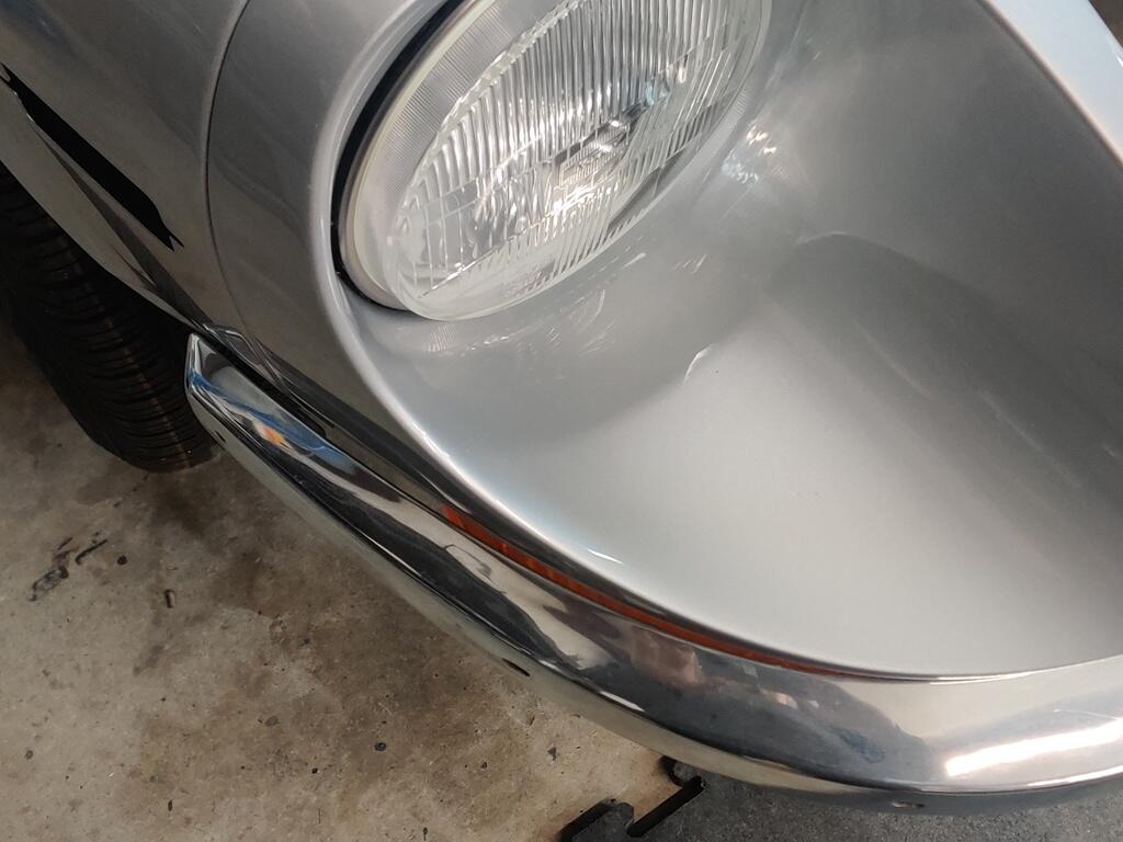
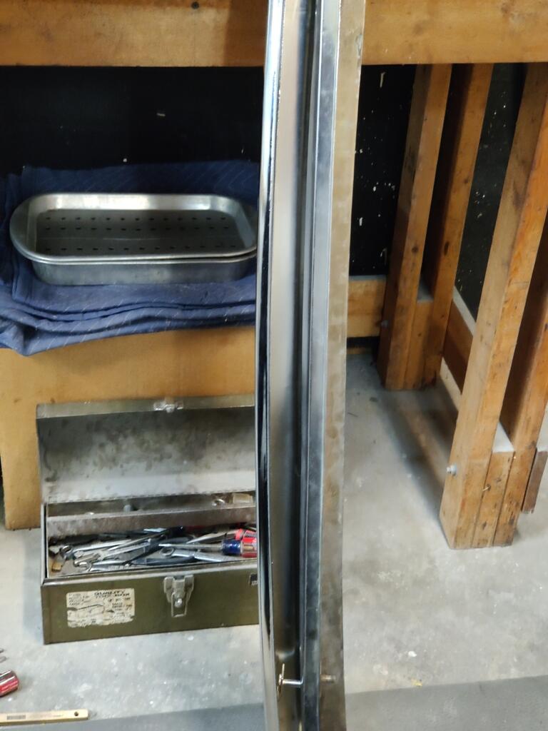
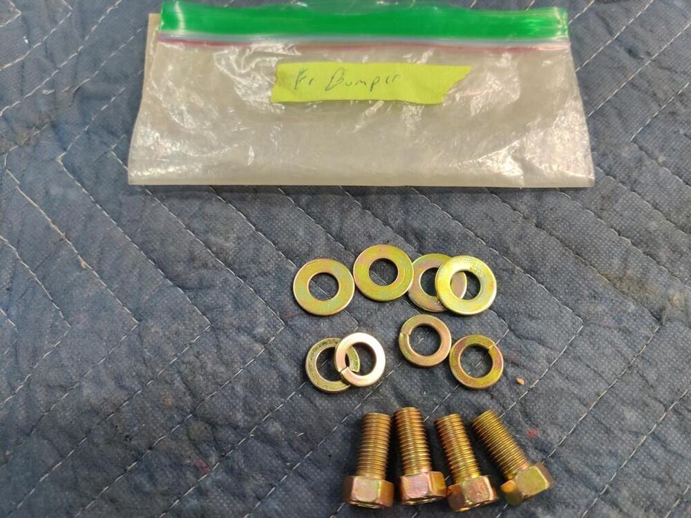
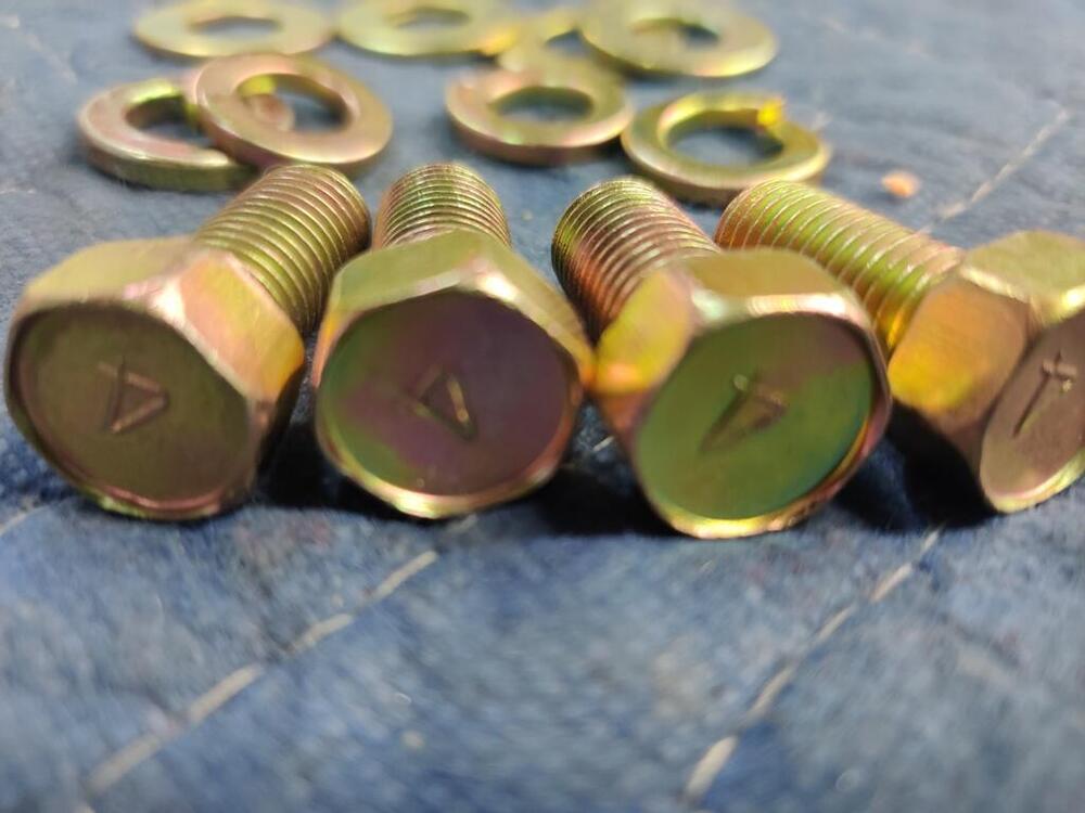
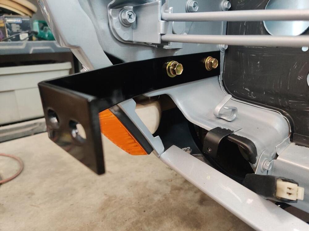
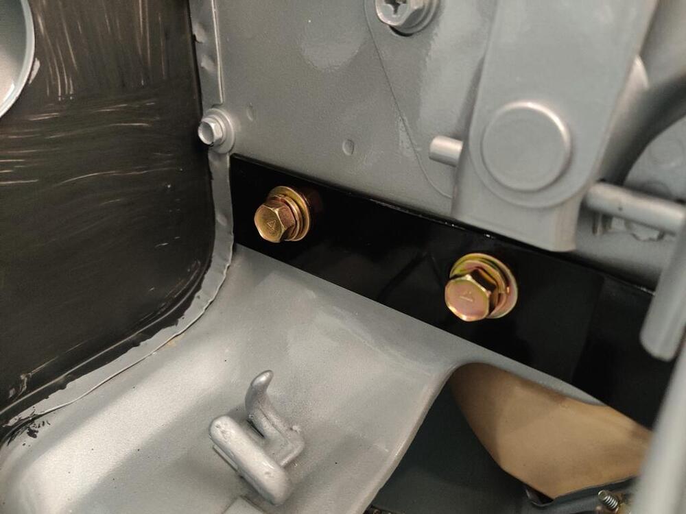
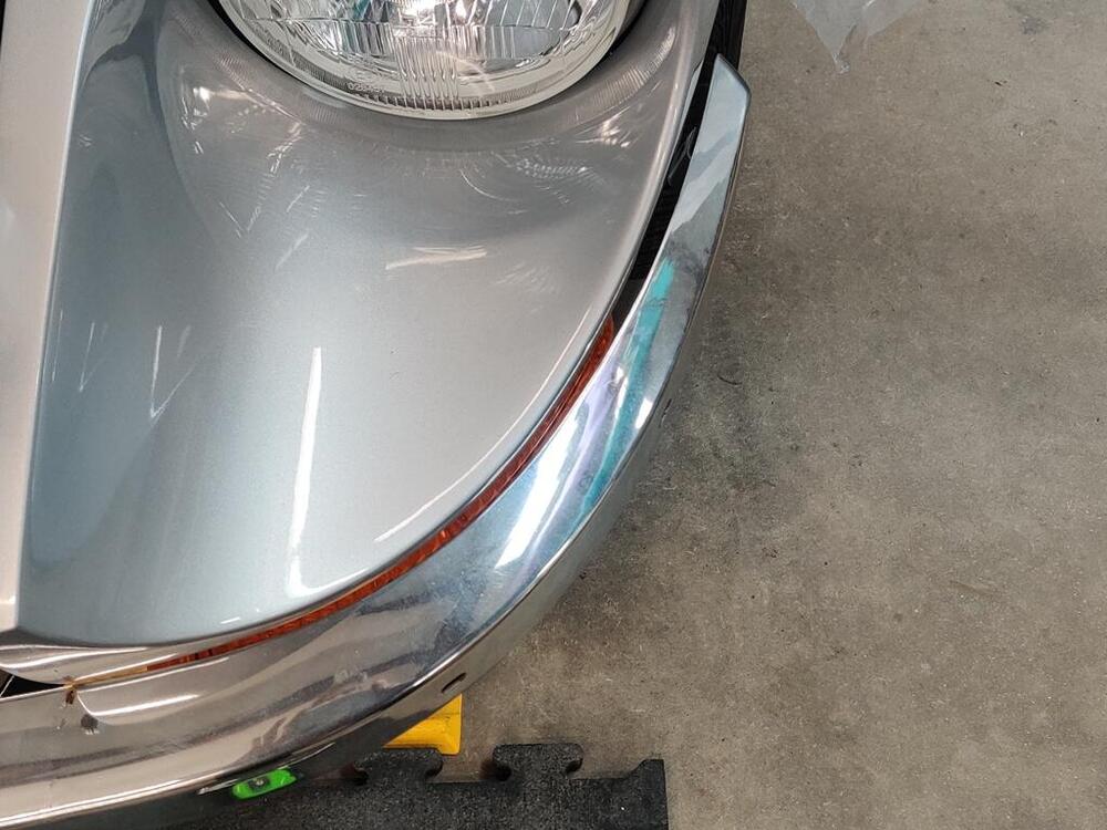
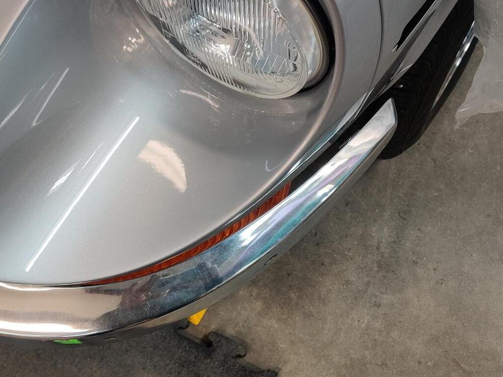
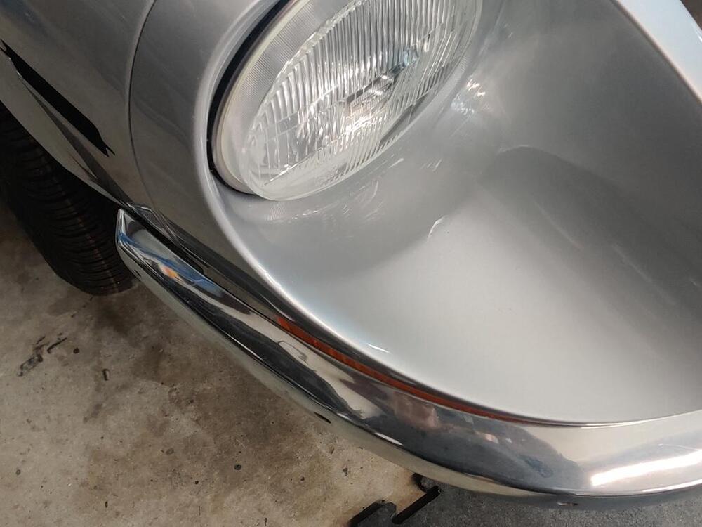
@dutchzcarguy - I measured 3.4 ohms of resistance. Yay! Tonight I put my focus on testing fit of the front bumper. I made note of asymmetric fit a long time ago and though I worked on it some to address that at the time, I want to resolve the issue completely before sending it off for re-chroming. While it looks pretty close, the bumper curve matches the curvature of the body on the the right side well and on the left side not as well. Those two picture show the difference pretty well. The curvature of the bumper on the left side of the bumper is less than the curvature of the body, causing the bumper end to stick out a bit. I double checked the left vs. right center alignment of the bumper. It is within an 1/8th of an inch of being centered. I checked the bumper mounting brackets for symmetry and that is good. So, I will see if I can work the left bumper end a bit to tighten the curve. I think it likely that the upper and lower surfaces on that end just need to spread a touch further apart. Doing that should tighten the arc. I also have been working on the original rear bumper. Pictures don't really capture what the issue is. This car was tapped in the rear, and the center bumper bar was "re-shaped" a bit during that impact. In this picture, a new old stock bumper is on the left and the original bumper on the right. If you look closely, you will see some of the rear "face" of the original bumper (on the right), especially in the center of the bumper bar. It also has less curvature over its length when comparing to the NOS bumper. When it was hit from behind the center of the bar was twisted... downward. I have been working it to restore its original shape using the NOS bumper as a guide. Generally, this involves using my hydraulic press and some pieces of scrap metal which I use to clamp the bumper in place. Then I beat on it with a hammer to attempt to reverse the "twist" it has. I also use the scrap metal as spacers, and use the press to push on certain areas to work curvature back into it. When looking at the picture above, I will be happy when I can get that rear face to not be visible at this same viewing angle. The curvature also needs to be restored to mirror the NOS bumper section on the left. Both the original bumpers are quite rust free, so I feel they are worth the time and effort to straighten. I also want to get the shape right before sending them to the plater. Then, they can focus on banging out the little dents, and grinding and straightening to remove the surface imperfections. I will be sending the original rear and the NOS rear bumper pieces, and two front bumpers, as well plus one set of over riders for the front and one for the rear.


-
Perhaps. You can try taking close up pictures and using zoom to see if that helps.
-
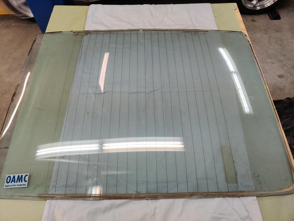
Hmmm. I will give it a shot. It looks to me like 2 to 3 of the lines off to one side of the grid have small gaps, but the rest looks good. Having a working rear defrost isn't a necessity where I live, but it would be nice. The other glass has more damage: more scratches and some kind of metal looking rub mark on it that won't come off.
-
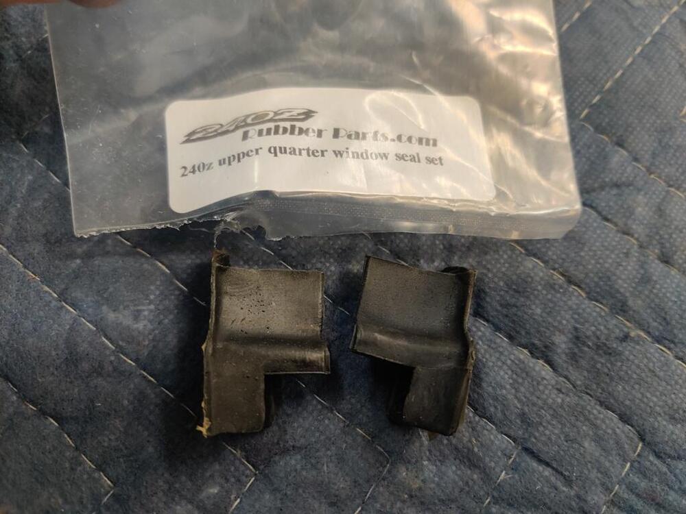
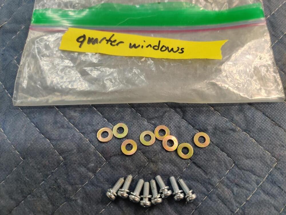
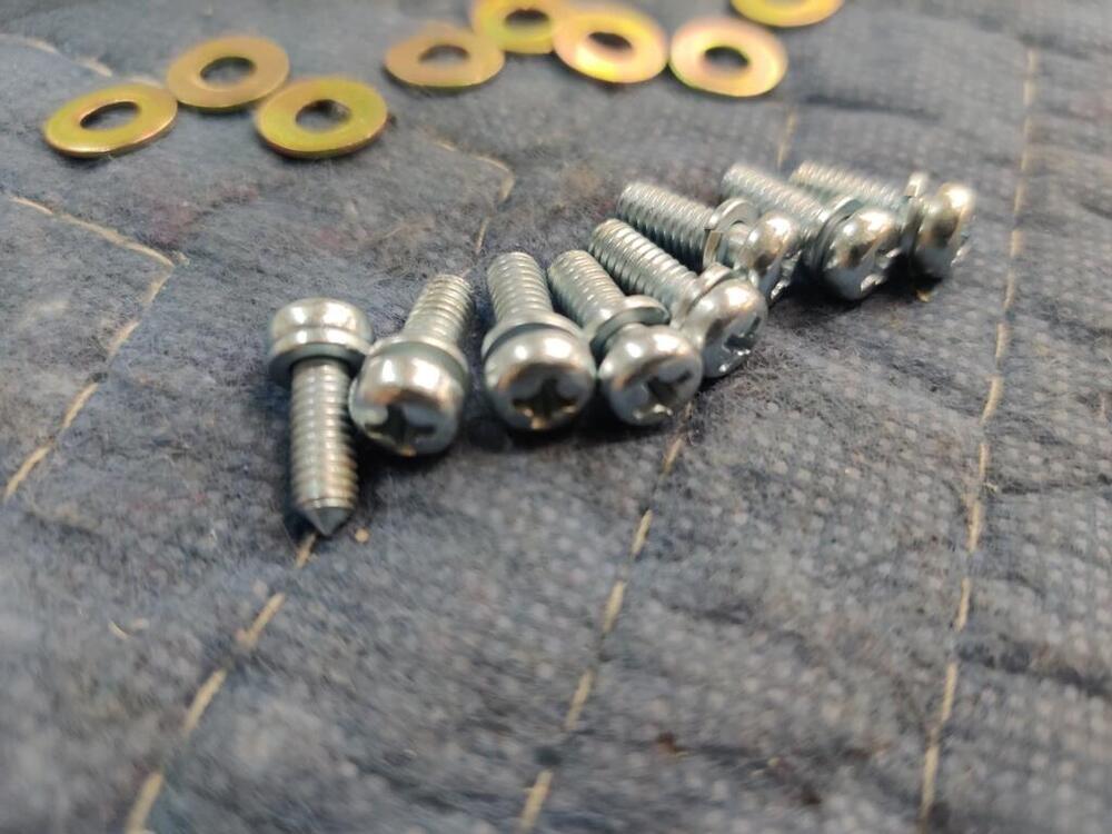
I forgot to mention that I spray Windex on the body of the car before putting the quarter windows in place. It lubricates the area so the rubber doesn't fight your attempts to compress it as much.
-
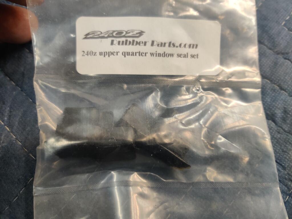
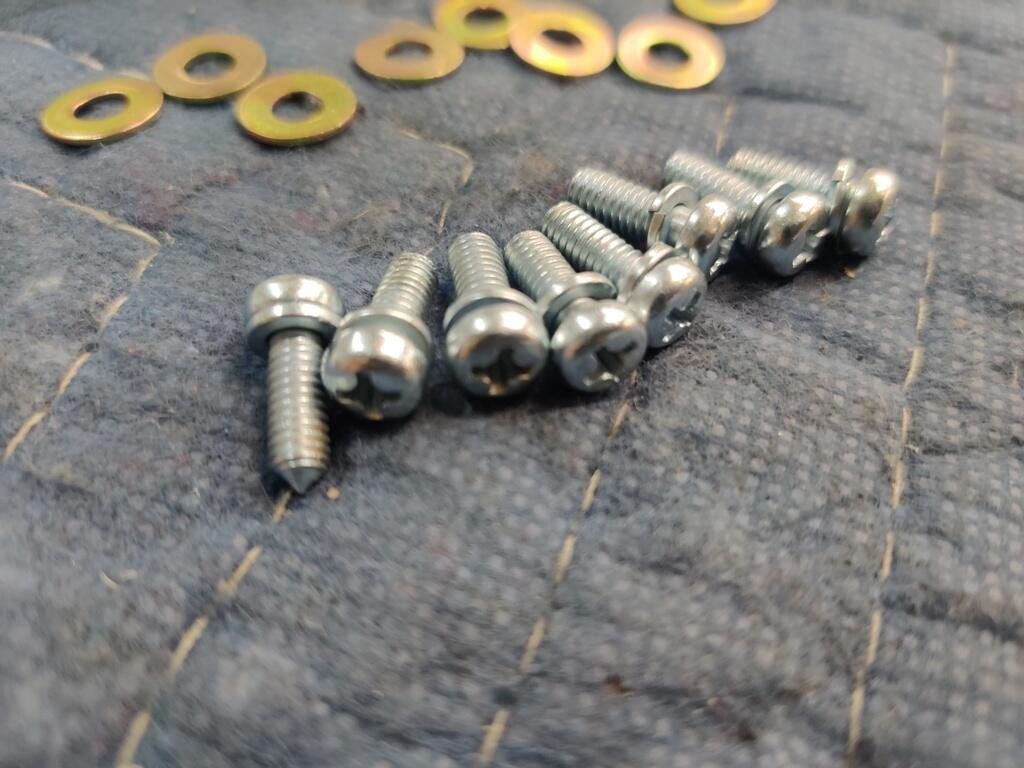
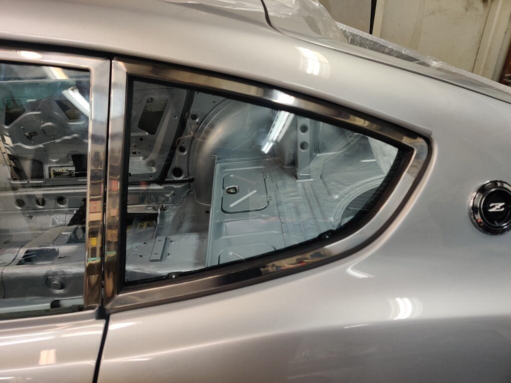
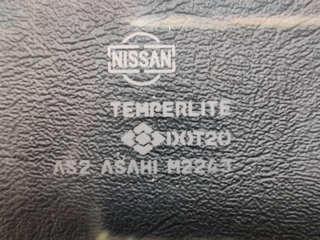
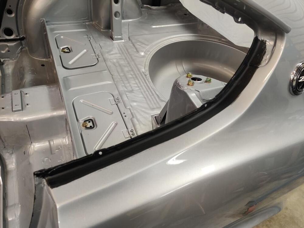
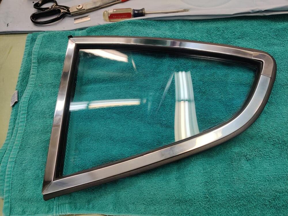
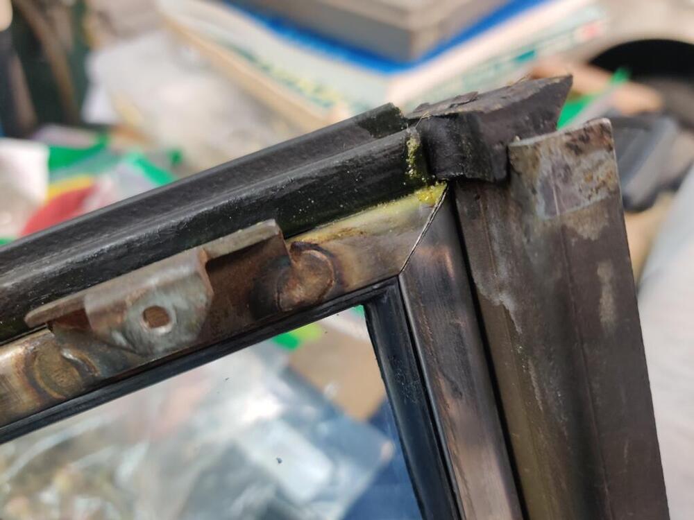
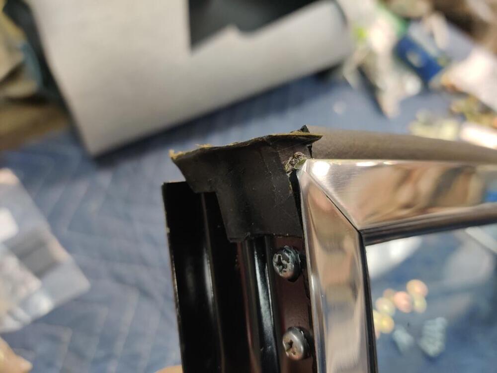
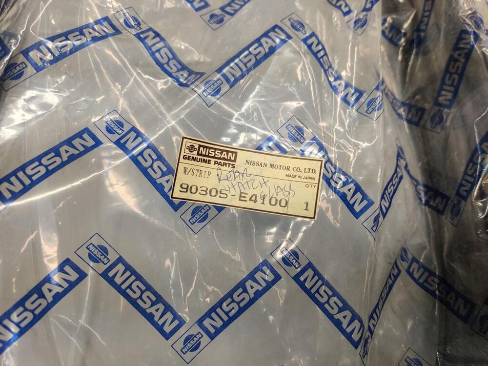
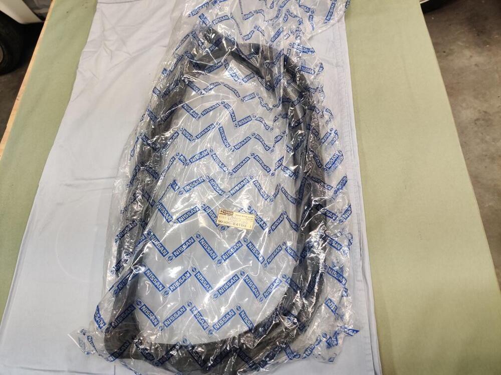
I was able to install the quarter windows this past weekend. I don't have quite enough door gap yet on the left side (last pic). I will let the weather strip that goes between the quarter window and the body compress a bit over a few days, and then attempt again to push it back a bit more away from the door frame. These windows can be difficult to install. I find the best way to do it is to angle the back part of the window out from the fully seated position, and secure the window with the two front screws first. Angling the back of the window out allows a bit more rearward movement. Once the two front screws are in, tighten them to snug while pushing the window back as far as it will go. You may have to push back pretty hard just to get the front bolts to align and thread. After snugging the fronts, push the back of the window inwards and thread the back two bolts in. Then snug those. If still too close to the door, wait a day or two and then loosen the screws, push the quarter window back further and retighten the screws. After I put these in, I shifted over to the rear hatch glass. I actually started cleaning up the wrong one at first. It was a spare that came with the car when I bought it. But, the etching showed July of 71, so I switched to the correct one, which shows May of 1971 (dot above P in TEMPERLITE (month) and S in ASAHI - year. A couple of tips for cleaning windows... Using a window scraper and fresh razor blades is very helpful to get the glass clean of dirt and grime. It will not scratch the glass not matter how aggressive you are with it. I find a razor blade is very effective for removing "rain spots" or other stuck on "hazing" from dried water. You may have to go over it many times, but it is pretty amazing how effective it is. For final cleaning of "hard water deposits" #0000 steel wool is the ticket. Again, the steel wool will not scratch the glass, and it is necessary to remove the final remains of hard water spots. Also, when you are trying to get the inside of the hatch glass that clean, you can't use a razor blade and scraper unless you want to gamble with damaging the defroster lines. Again, using the steel wool, you can go directly over the filaments. It does a great job of getting stuck on crude that cleaning does not remove. Finally, I wrestled with installing the rear hatch weather strip. I did not expect it to be so difficult, but after about an hour I was able to get it on, but was a bit worn out from the effort. 😁 I also made some notable progress with the issues I have been having with the differential. I am looking forward to getting that done, so I can install it and all the things that are being held up by it.


-
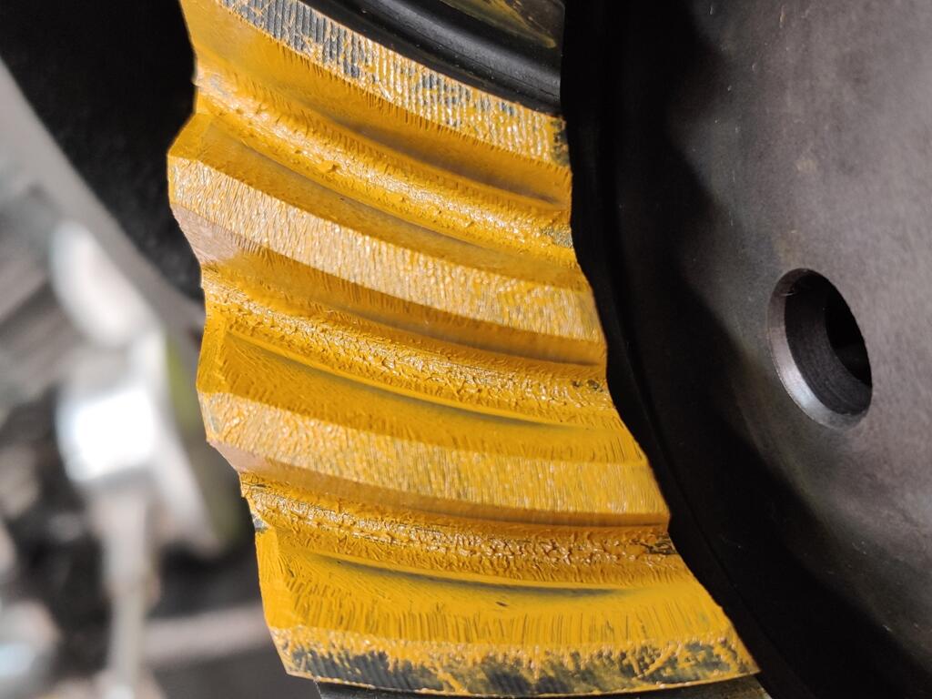
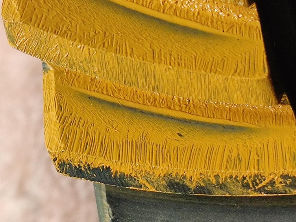
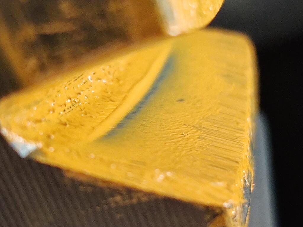
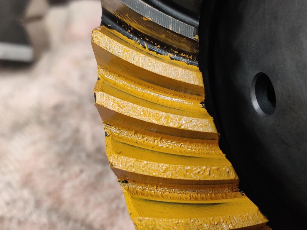
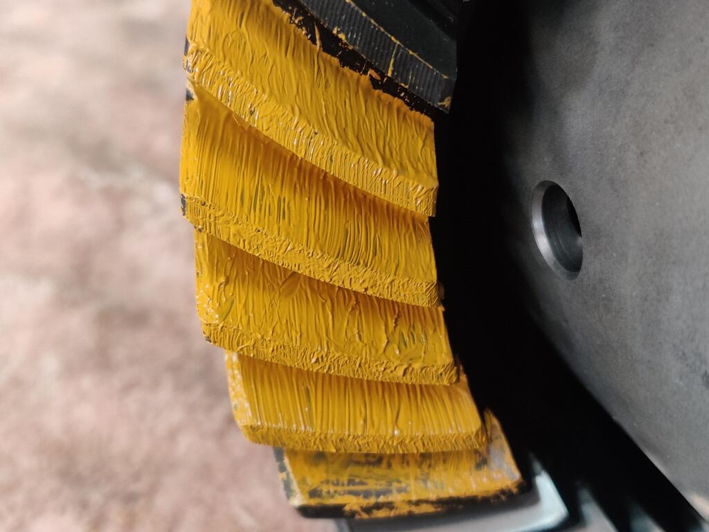
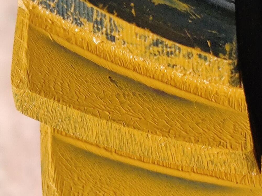
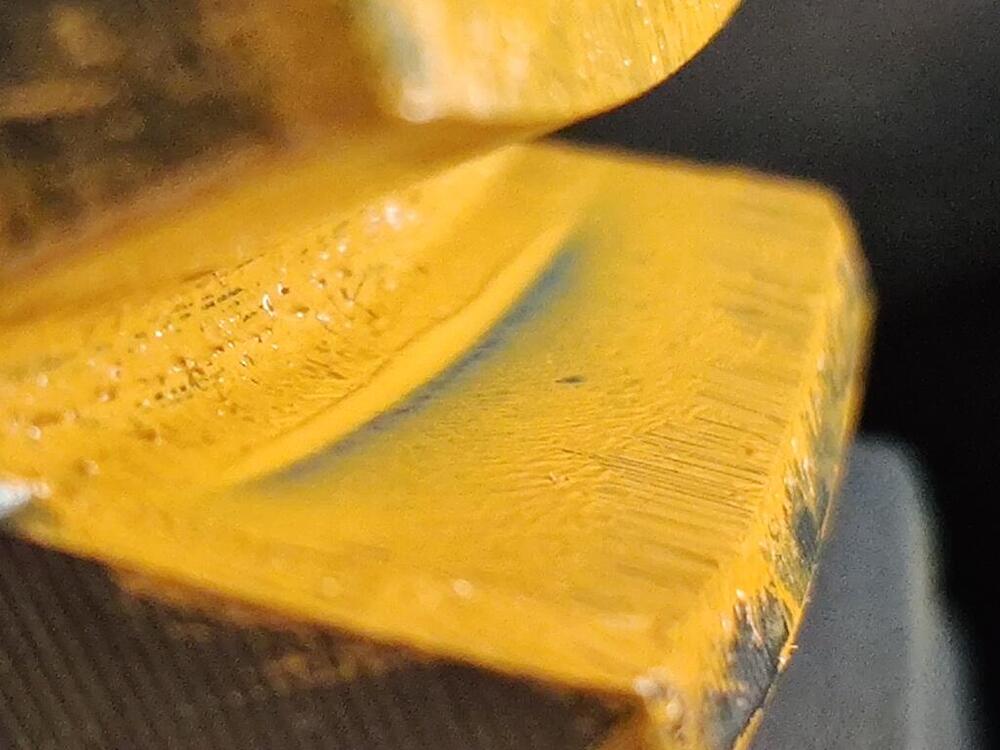
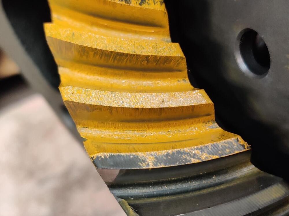
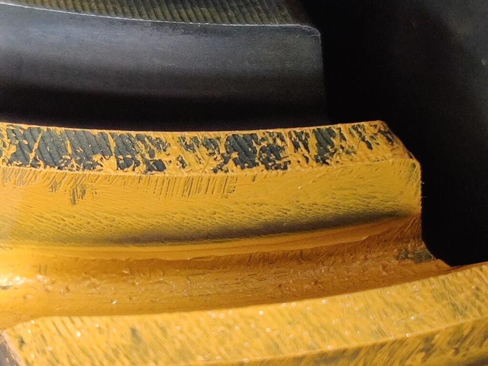
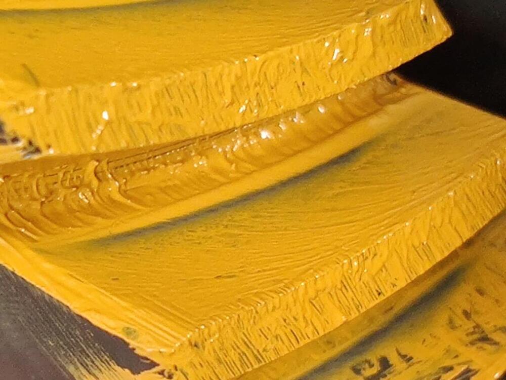
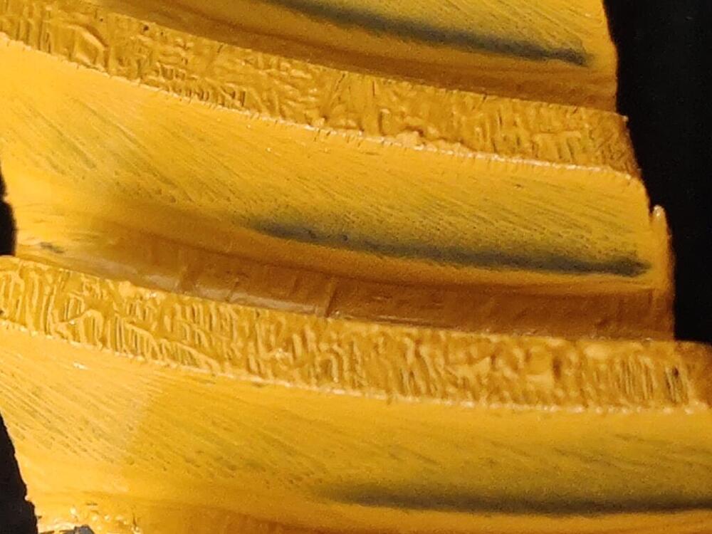
On Sunday, I took the diff back apart and reassembled it with .020" of additional shims instead of going back to the .015". The reason for the change? I just figured I'd learn more if I tried something I had not before. First, one pic showing the wipe pattern on both drive and coast sides at the same time with the .030" of shims: Note the wipe patterns are offset. You see it is to the left on the coast side and to the right on the drive side. Ideally, the contact would be in the same area on both sides of the teeth. Now a pic after switching to .020" of extra shims: Ha HA! This is better. With .020" of extra shims, and the .3 mm shim on the left and .4 mm and .5 mm shims on the right, I measured .009" of backlash. When I tried to switch the .3mm shim to the right with the other two, I noticed that everything was bound up as I was tightening the side flange bolts. I was careful to not tight them all the way as it was clear that I had zero backlash. So... I think I am very close to the correct pinion shim size now, but I am thinking I may need to alter the side flange shims a bit to get the backlash within factory spec. Time to order some more side shims to experiment with. More pics of contact pattern with .020" of extras shims - I have been putting the paint on thinner so it is easier to see the pattern:


-
I will never know for sure. However, I got the timing chain off by one tooth (it has a Kameari chain tensioner set up) and the valves contacted the tops of the pistons for a few minutes upon start up while it was like that. I corrected it, and went to Road Atlanta for a track day a week or so later. During the fourth and last session, I had a rod bearing, and then rod let go at over 100 on the main straight. That block had holes on both sides when I pulled it out. According to another Z racer, turns 6 and 7 do a number on cars that run there. He has an Accusump in his Z (and an 8 qt Nissan Competition oil pan like I was running) and he said he sees the Accusump "working" on that part of the circuit, meaning oil pressure is dropping under the high G load.
-
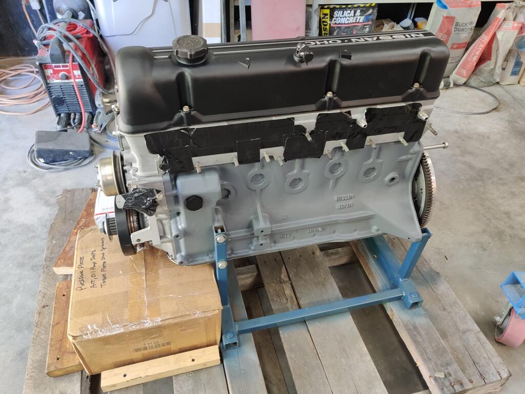
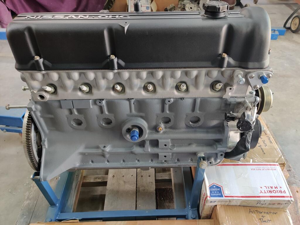
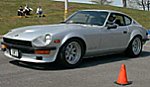
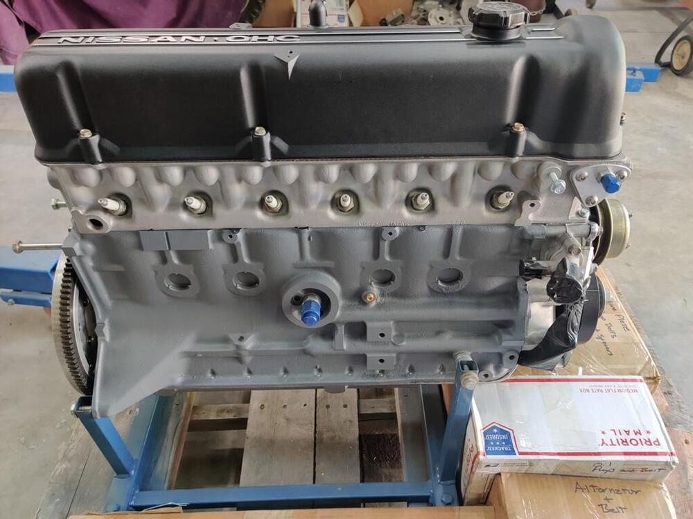
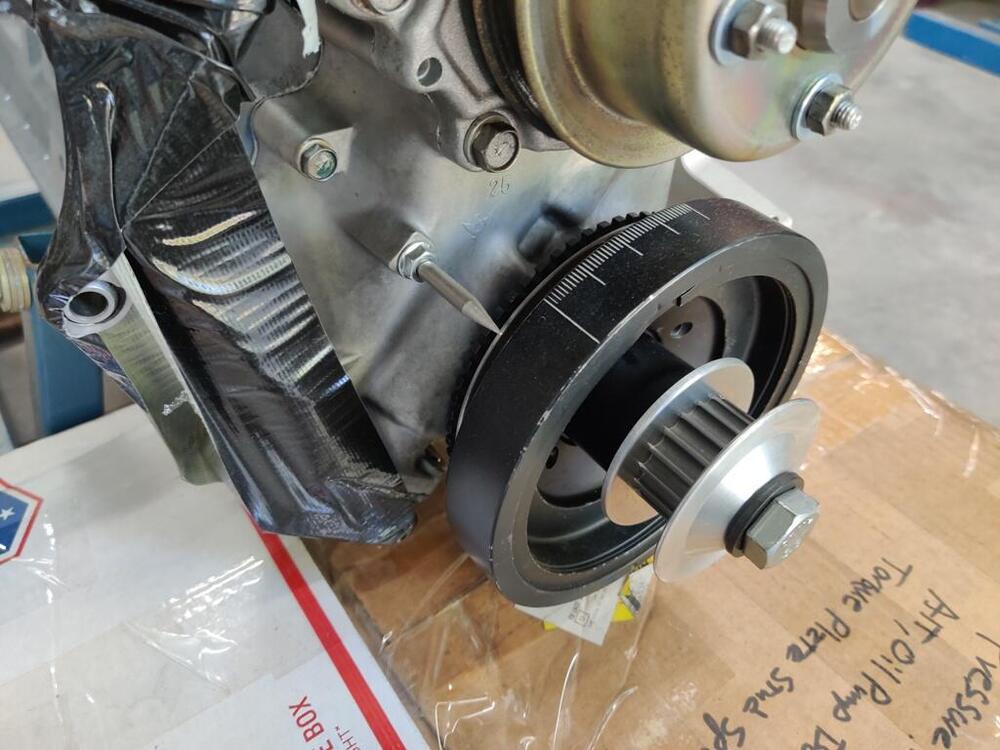
Dropping the clutch for launching will have to be handled by my other Z - when I am in that mood 😉. I have a replacement engine for that one sitting on a stand and a few other upgrades planned before I can fire that beast up again. It will be worked on this year for sure. This is the old engine, which I broke at Road Atlanta back in August of 2015: This is the new one: This new engine is very similar to the one I destroyed. Changes include an 89 mm bore, (is now a 3.0 liter vs. 2.93 before), same cam and valve train except intake valves are titanium this time and were stainless steel before. And this time the crankshaft not lightened and knife-edged, but it is still offset ground and combined with eagle rods to get to the 3.0 liters. This new engine will utilize a dry sump oiling system. But, I digress...


-
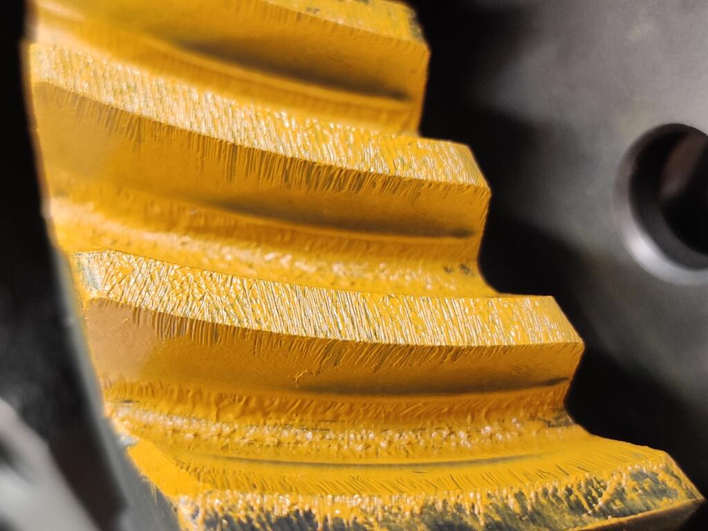
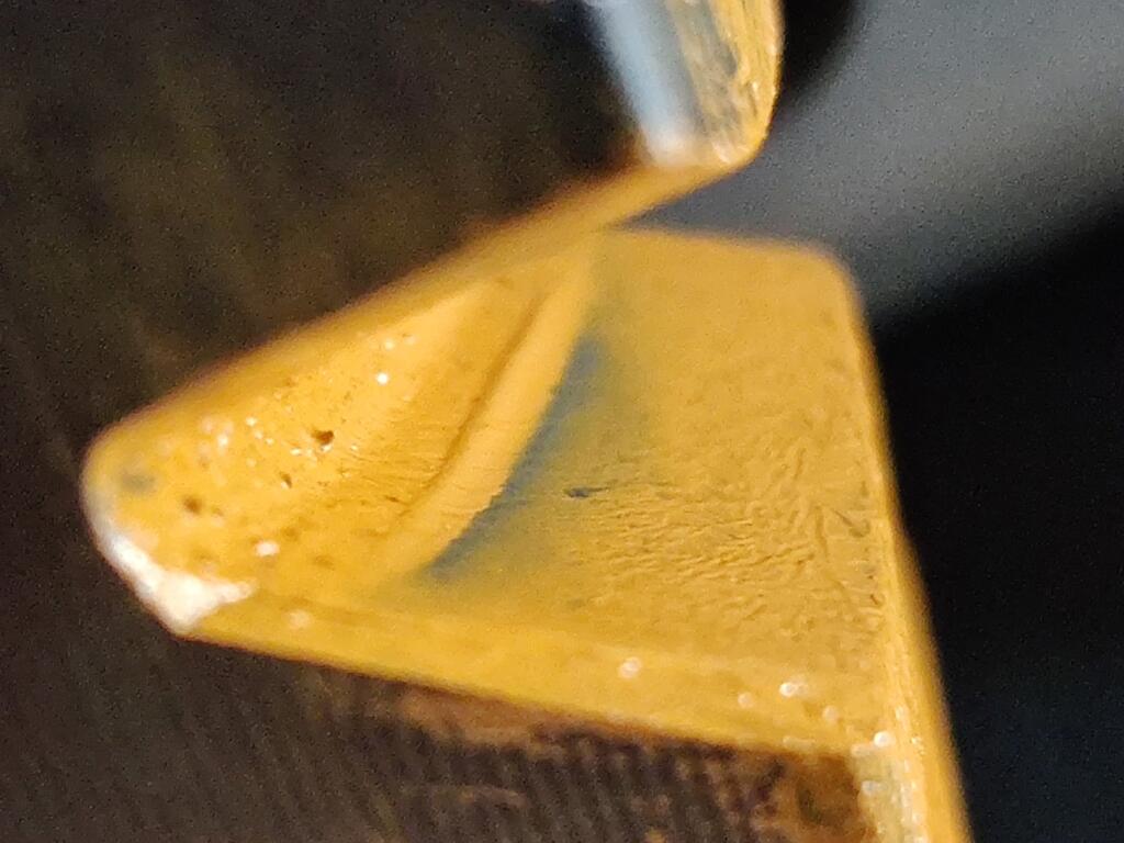
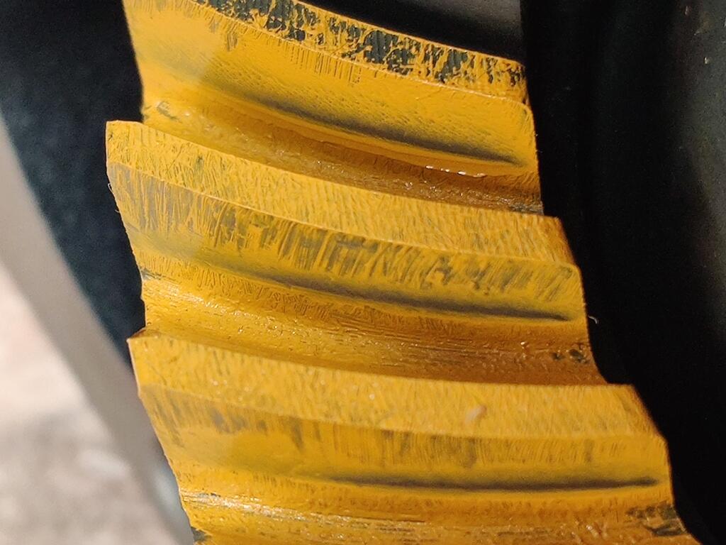
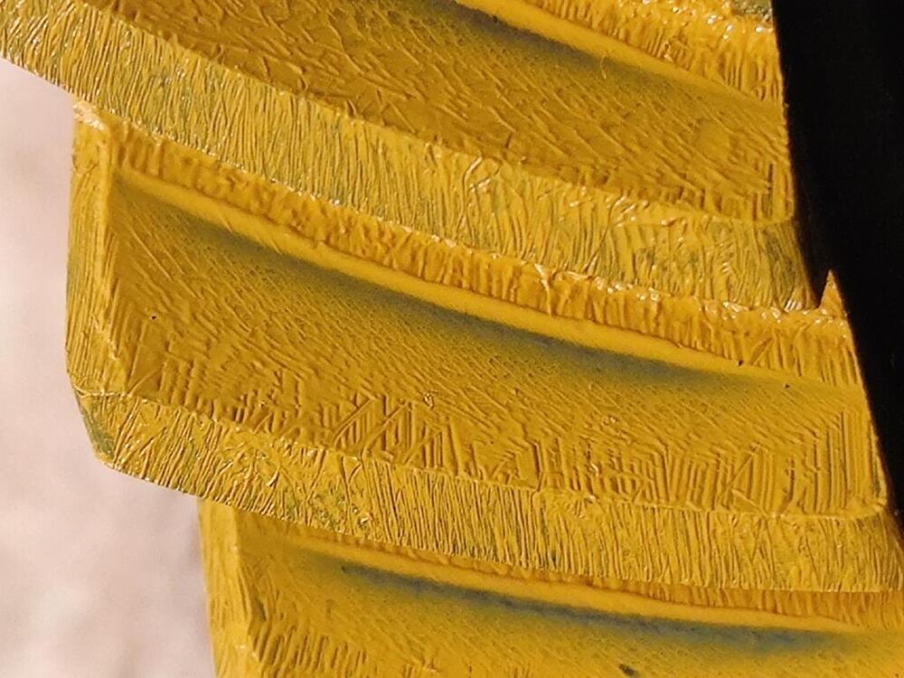
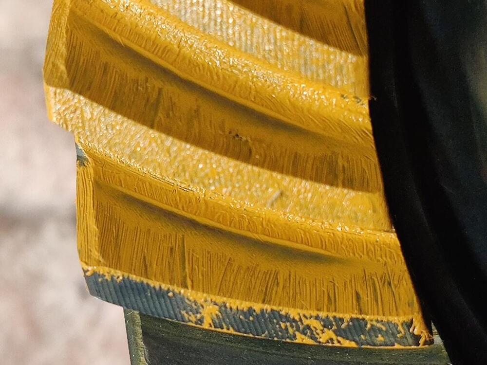
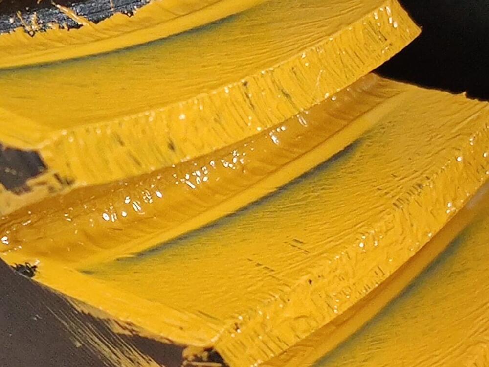
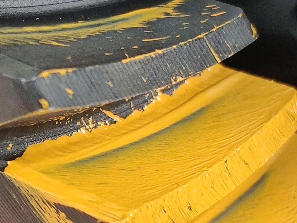
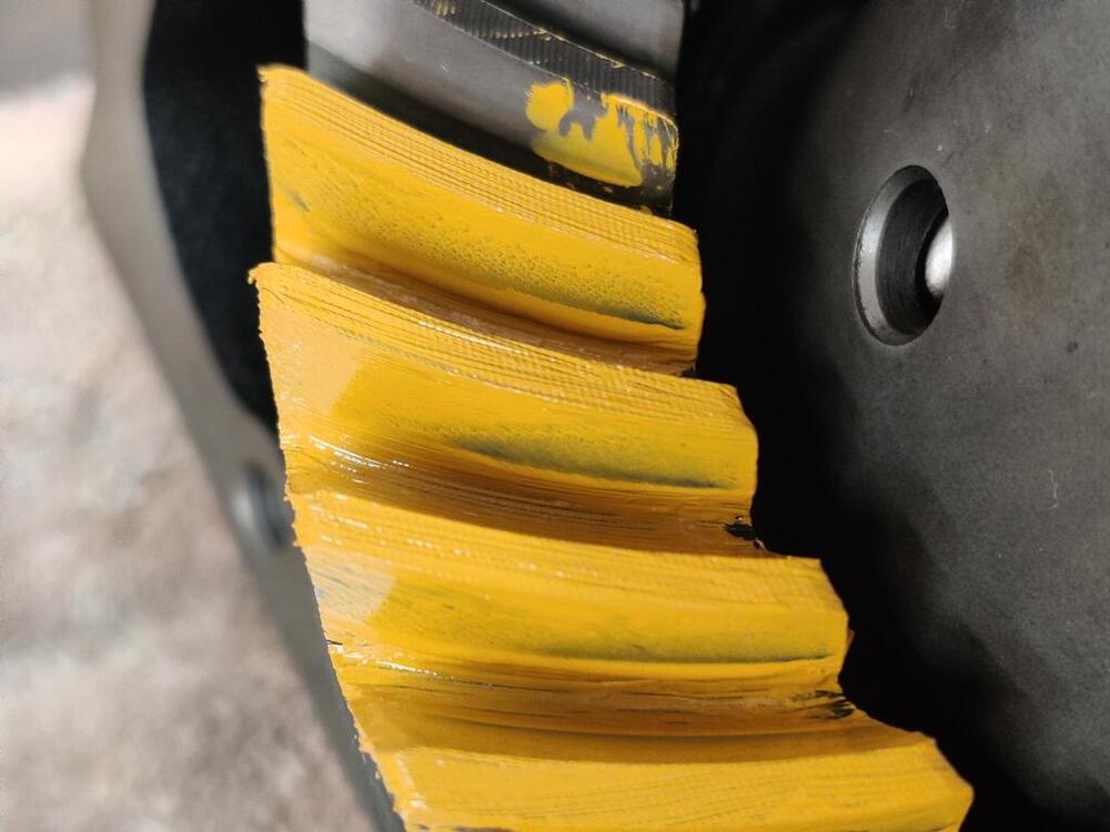
I worked on the differential again today. I was surprised that upon taking the carrier out for about the 15th time, it "fell into" a different spot, I was able to remove it from the case with "more than enough" clearance where I had ground the case on the left side. I feel like an idiot - I didn't have to grind as much of the case as I did. Anyway, I'm not going to think about it anymore. I'm not going to be abusing this car, so hopefully I won't have a problem with the case where I ground it. If I do have a problem later, at least I will have the experience behind me of how to assemble one of these properly. I put another .015" of shims onto the pinion gear, added to the original .126" shim and the .015" of shims I had already. With .030" of additional shims, I assembled everything again. I put the side flange shims into their original positions. I measured back lash at just under .009". Disappointing. It will need to come back apart and more shimming experimentation performed. ☹️ I went ahead with checking the wipe pattern. This time, I made the brush strokes perpendicular to the gear teeth, so it would be easier to see where the gears contact each other. Drive side and coast side, respectively: Drive side: Coast side: I learned today that when meshing the gears together to check the wipe pattern in the paint, there needs to be a light load of resistance. In other words, when turning the pinion gear to drive the ring gear in the direction to move the car forward, dragging on the gear with one hand loads the ring gear teeth against the pinion gear teeth to show the pattern better. If you don't load the ring gear, the gears "float" a bit more and leave a less visible impression in the paint. Same is true for rotating backwards. Apply some drag with one hand to load the ring gear against the pinion to make the pattern more visible on the coast side. I think I see what has happened here since last time. This time, the contact area on the coast side has moved more toward the heel end (outer edge) of the ring gear. And, it looks to me like the contact area on the drive side has moved a touch more toward the toe end of the gear. If the pinion is either too "short" (needs to be moved toward the ring gear) or too "tall" (needs to be moved away from the ring gear), the wipe pattern will not be in the same area of the ring gear teeth on both the drive side and the coast side. If the pinion is too "short", the contact area will be more on the heel of the drive side, and more on the toe of the coast side. If the pinion is too "tall", the contact area will be more on the toe of the drive side, and more on the heel of the coast side. So... I think I have too much pinion shim now. Looking again at the pics from last time (.015" additional shim, and all three side flange retainers on the right side, which resulted in a backlash of .005"): I think the contact area is more centered on the coast side (first two of the three pics above). And I think the contact area is a touch more toward the center of the drive side as well. I think what I will do from here is go back to the previous set up. Regarding the contact area appearing lower toward the base of the tooth, I think that putting a load on the ring gear may help to show more clearly that the contact is actually more centered than it looks in those pics from last time. The second pic above gives me hope. We'll see. Also important to note is that there is some additional flexibility with the pinion shims. Right now, I have a .3 mm on the left and a .4 mm and .5 mm on the right. They are sold in the following mm sizes: .2, .25, .3, .4 .5. As long as the combination I use adds up to 1.2, I will keep the pre-load where it needs to be. So, these are equivalent options, but move the ring gear toward the pinion differing amounts: .2 and .5 + .5 .25 and .25 + .2 + .5 The learning continues.


-
Ummmm... well, I found out today that I didn't need to grind that much. Yeah, I didn't realize until today that I ground more off than I needed to. As I was taking the carrier out today, it "fell into" a different location, and I was able to "make the turn" as you say. I feel like an idiot now. Hopefully, I haven't ground too much as to weaken the case and cause an issue. The key is to butt the ring gear up against the right vertical wall of the back of the case, and then rotate the carrier as you push it in.
-
Not a problem. We do have a lot of work to do. FYI- the Nissan folks are subsidizing a promotion for the entire month of Feb: "From 2/1/2024 through 2/29/2024, we’re offering Nissan owners 15% off select genuine Nissan parts and accessories* & free shipping on orders over $75 with the code FREESHIP.** "
-