inline6
 Subscriber
-
Joined
-
Last visited
Everything posted by inline6
-
 I put mine back in. I also like that lower torque setting. Where is your seal? It is missing from the picture you shared. It goes in before the axle flange goes on.
-
Good thought. I do not have grit numbers or know the materials. I could experiment with some fine grits... I am going to try to use the finest grit again, specifically on the right side area of what I worked. I want to see if spending more time and effort with that grit makes the step of transitioning to the liquid polish work more quickly. If I don't get noticeable improvement from that effort, I may experiment with some very fine grit sandpapers on both a rotary and a DA. I think the DA will be worthless. Glass is much harder than paint.
-
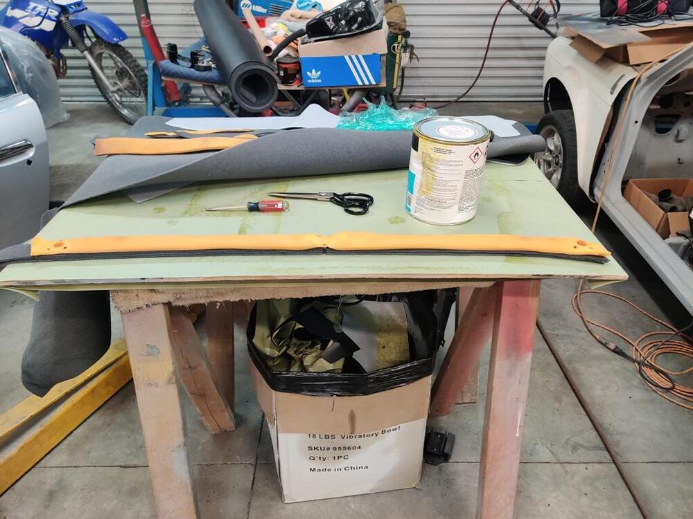
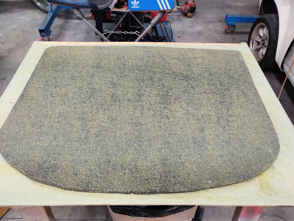
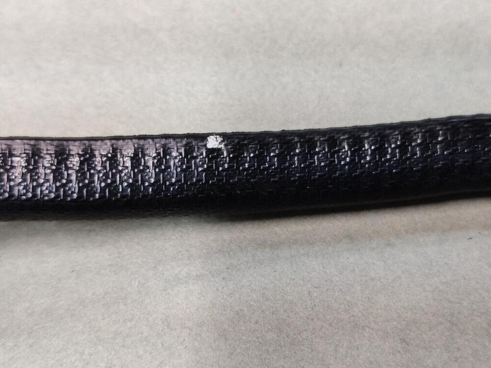
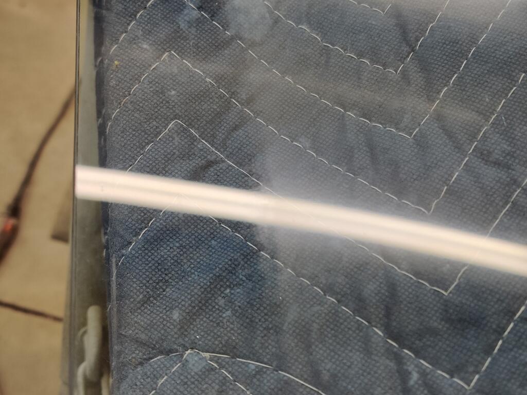
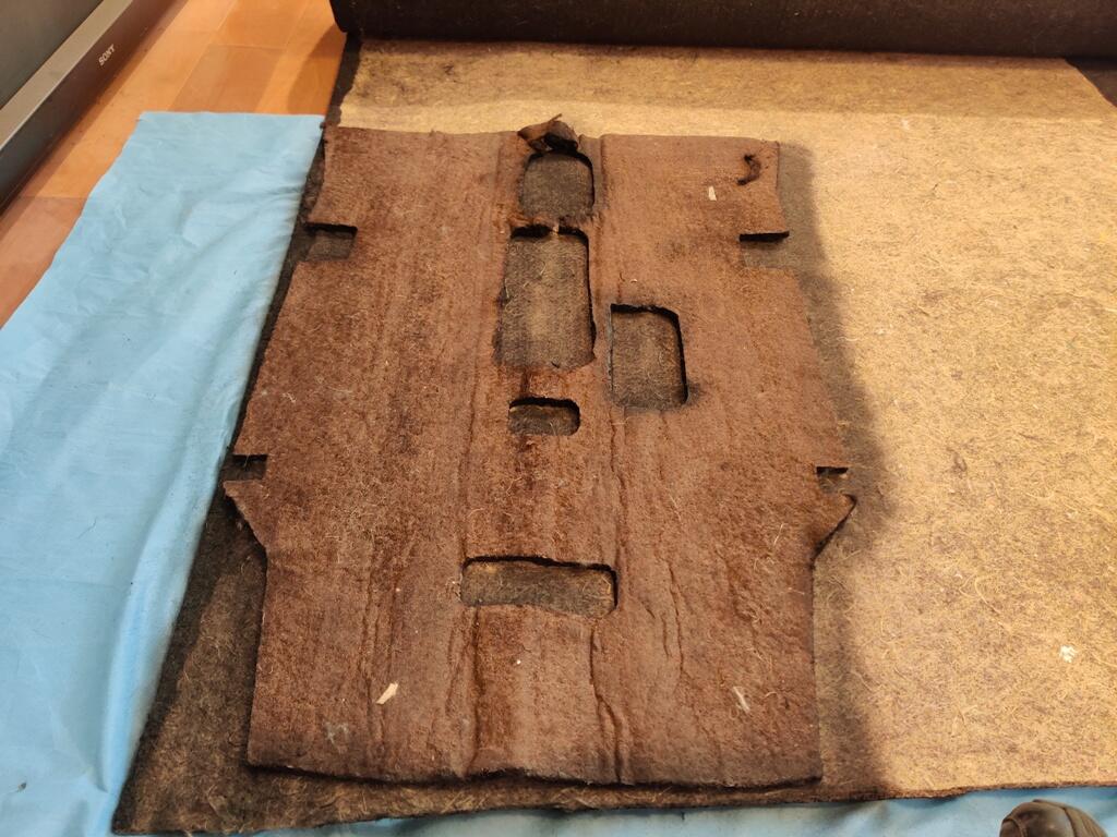
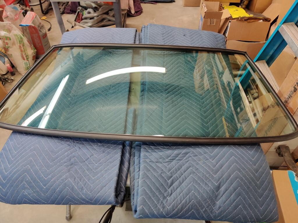
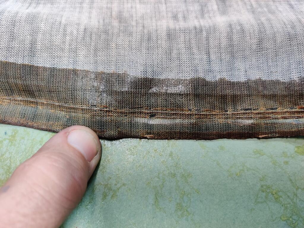
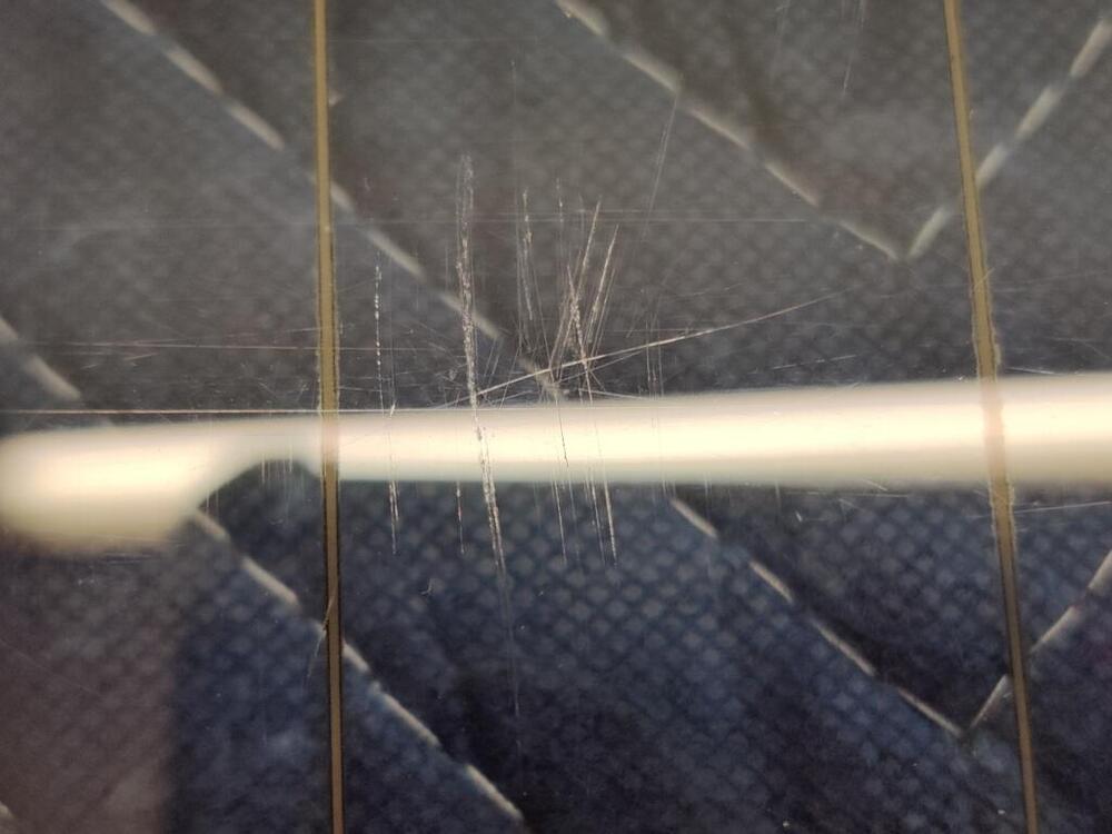
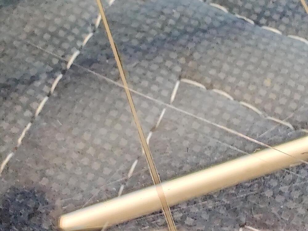
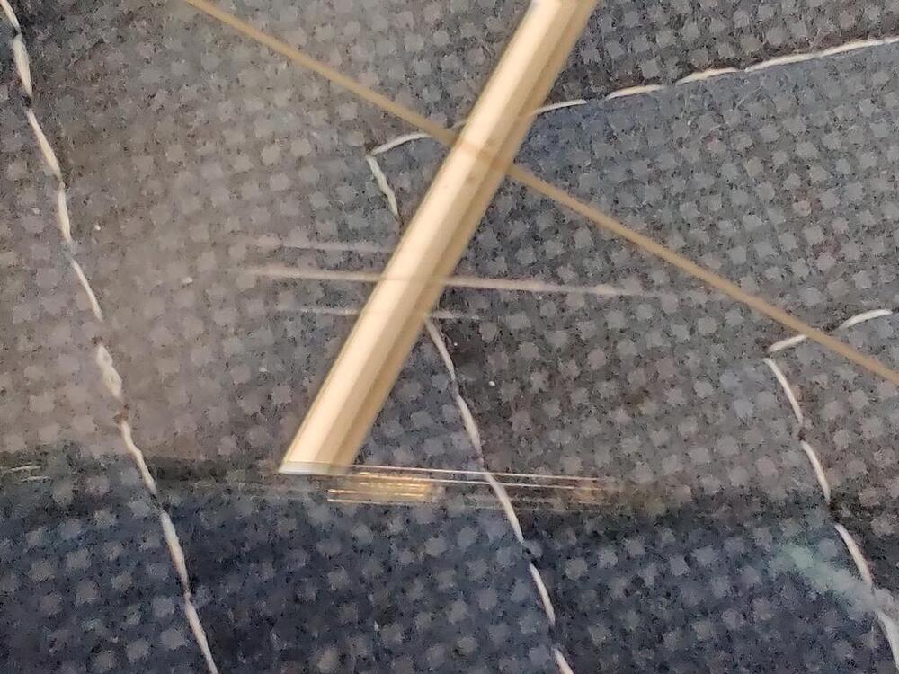
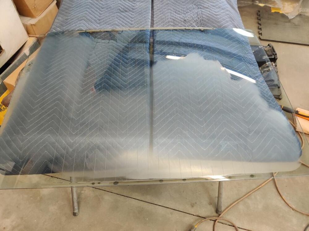
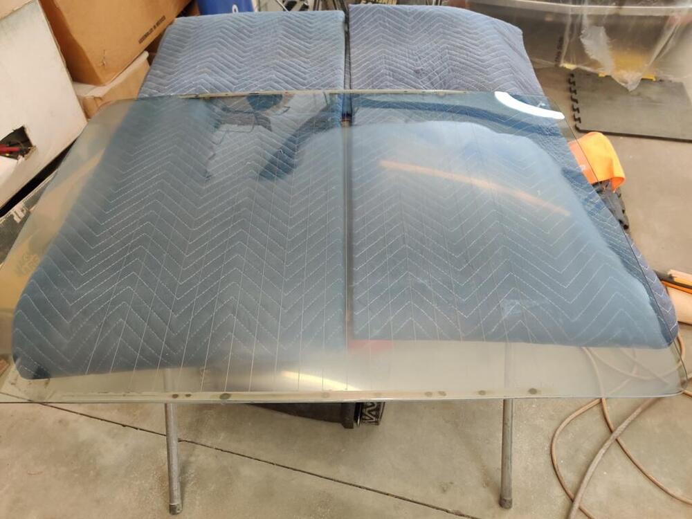
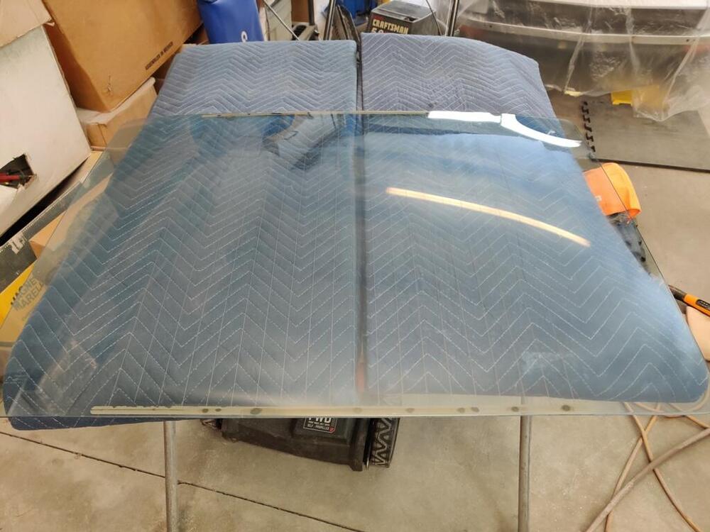
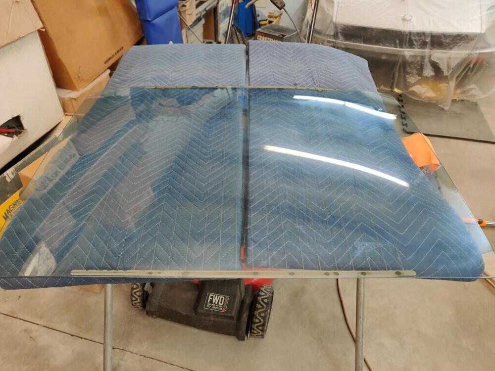
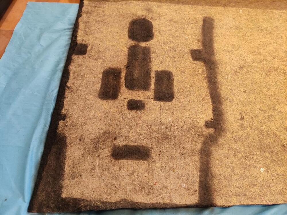
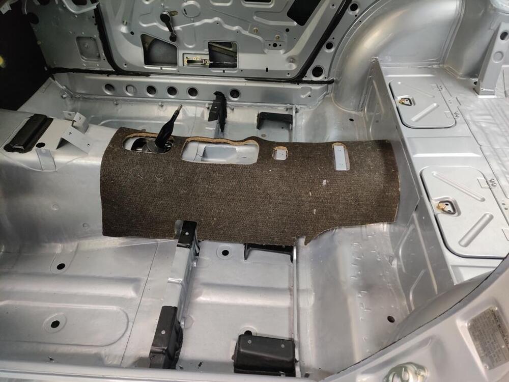
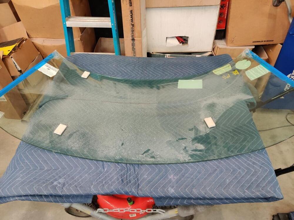
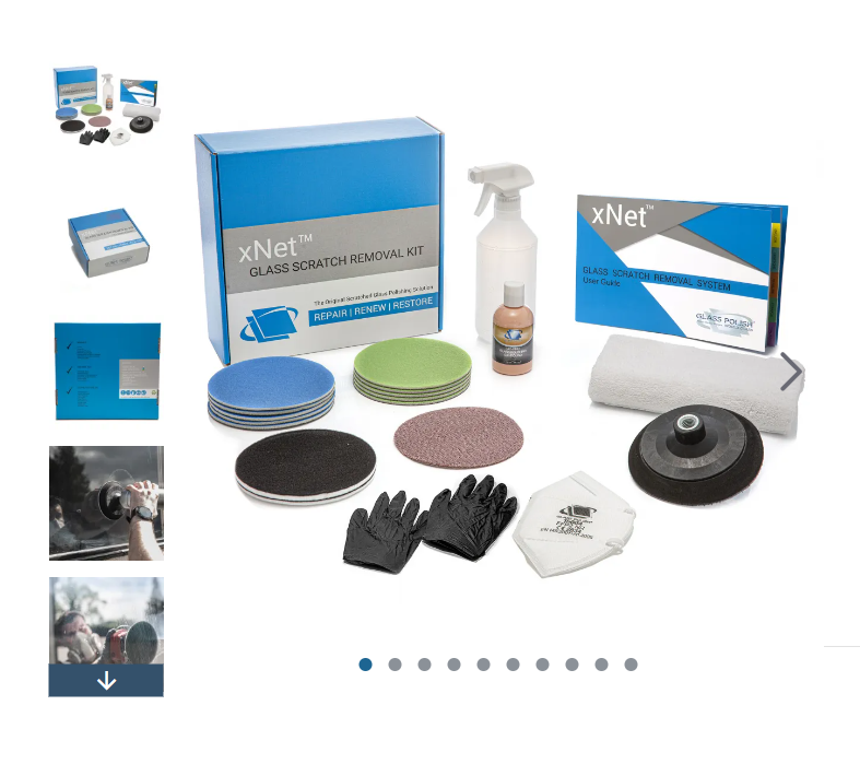
With the windshield in, a significant barrier to installing the dashboard had been passed. However, there are still a few things that need to be done before it can go in the car. One of them is installation of the tunnel jute and trim. And that will need to be followed by installation of the heater core and housing and the fan its housing. I started on the tunnel jute today. As I mentioned before, I bought a roll of jute from England that looks similar to the original. It is dark brown on one side and tan on the other. I placed an old piece of jute on top of the new, and used black spray paint to mark where I needed to cut. I got mixed up for a minute on which side needed to face up, and marked the wrong side for the handbrake cutout at first. But, I realized what I had done before I began cutting and flipped the old piece over. After marking the correct side for that, I used my upholster shears to cut the jute. I nice pair of upholstery shears is a necessity for cutting this - they cut through without difficulty. So, I got the rear one made today, and just set it in the car for this one pic (third pic here). After that, I decided to tackle the job of removing the scratches from my rear hatch glass. As you can see, there are a few - the white beam is the reflection of a florescent light in the shop. I opened up the kit I received recently, and put the attachment on my rotary buffer. The kit I bought has three different sanding grades and a liquid polish solution. I started with the heaviest grit, putting it on the backing pad. Kind of scary to use this grit as it is super aggressive. One thing to note, I think that out of the box, the heaviest grit "pads" had some oversized grains on it. During the first 20-30 seconds of use, it put some swirl scratches in the glass that took a bit of work (with the same grit) to get out. The kit came with two of the heaviest grit pads. I think it would be wise to run fresh ones very lightly at first to knock any unusual bits in the surface of the pad down a bit before you go to town with it. That, or run it on a piece of glass that doesn't matter to you first. Anyway, with the first grit, glass removal is relatively quick. I could catch my finger nails on some of my scratches, however, there was not much time investment in cutting the surface of the glass down to past the scratch depth with this grit. When I was done with the first grit, I took a picture. As you can see, a portion of the glass towards the top, center and right side, did not need heavy scratch removal, so I left that area alone: Next was grit number two. I went over the entire area that I had hit with grit one. It was easy to see the difference in surface finish of grit two compared to grit one. Like the first grit, the second grit cut pretty quickly, but more time was involved in getting all of the areas I had worked with grit one to "grit two" level. When done with grit two, I took another picture: I repeated the procedure with grit three. I want to say that I getting the surface of the ground area to "grit three" level took a quite a bit longer. Again, I could see the difference pretty well. So, I kept at it until everywhere that had been ground looked uniform, and I couldn't see any heavier scratches from the prior grit. I took another picture: At this point, I had about 2-3 hours invested. And I switched over to the liquid polish stage. This stage did not go great. Based on my efforts today, getting rid of "grit three" hazing is going to take a very large time investment. I think there are a couple of areas where I did not sufficiently remove grit two, mainly on the right edge in the pics above. So, I may have to hop back to grit three for that area. However, I am confident that for most of the area I have worked, I did a good job of using each grit to remove the prior grit's marks. And unfortunately, this last stage of polishing is going to be a bitch - like maybe 4 or more hours of intensive polishing. I wish there was another grit between grit three and polish. Of course, I could be doing something incorrectly also. So, I will look at the company's website for some tips and watch some of their Youtube videos to see what I can find out. Latest pics - second one is that right edge ( I took the picture from the opposite side of the glass) where I think I will need to rework with grit three.


-
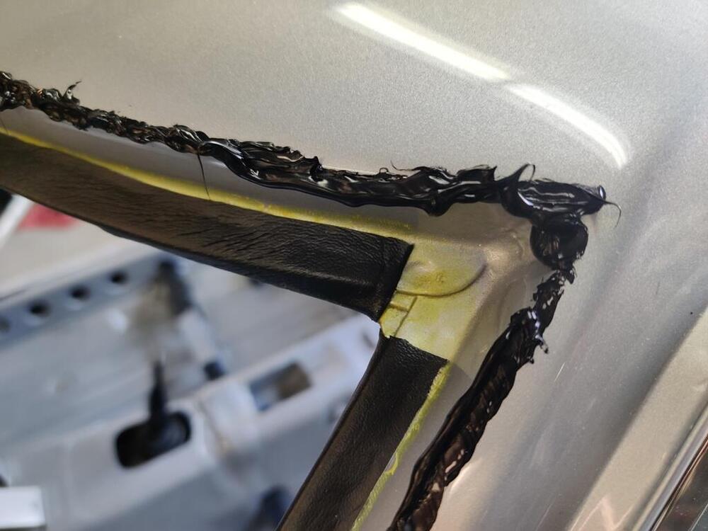
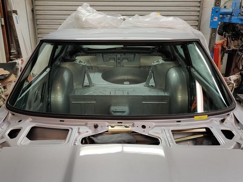
With some help from a friend, I put the windshield in the car today. I have done this on a 240Z only once before, back when I was restoring my track 240Z in 1993. I also have put a couple of Datsun 510 windshields in. For the "rope" in the channel, I use 12 gauge insulated multi-stranded wire. Perhaps rope would be better, but I like the solid feel of the wire rather than what I imagine might be a "stretchy" feel of rope. Additionally, I use dish soap (slightly watered down) and an acid brush, applying it onto the frame of the car and the windshield rubber gasket where it contacts the body. I try to eliminate friction so the rubber lip that has to be pulled inside the car is free to move. This time, I used black urethane adhesive and put it on the windshield frame where shown in the diagram in the factory workshop manual. What an mess it made during the installation procedure! I got it all over the place, and it easily took 2 hours to clean it off the car and off of me. I decided to put the stainless trim in after installing the windshield. Wish me good luck on not tearing the rubber as I install it. I have yet to examine it and correct any scratches, so that will have to come first.

-
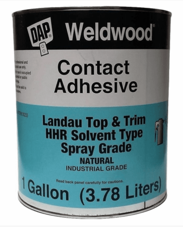
I highly recommend the contact adhesive I am using. If you let it sit for about 2-3 minutes after applying to the body and the rubber, it sticks extremely well.
-
I may be able to get inside scoop as I have some contact with Nissan USA folks.
-
Just seeing this - spoiler though - they don't have plans to sell it. 🤪 I think they must have had plans, but maybe they do not any longer. https://www.thedrive.com/news/nissan-develops-major-240z-head-upgrade-decades-after-its-retirement
-
If you use a bit of rubber silicone grease around the shaft before installing the boot, it will be a water proof seal there for many years to come.
-
My hardware was nearly perfect and yes, the plastic parts came out like white chalk. Thanks for info. If I have more parts to have plated, I will pass along the recommendation to shorten the time in the hot acid.
-
How is it that the parts with plastic on them you have re-plated like the fuel rail and the throttle rod don't have plastic damage?
-
Did they do anything special to get the windshield to go into the car so easily?
-
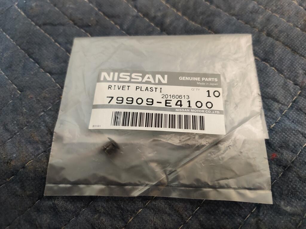
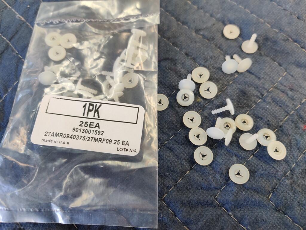
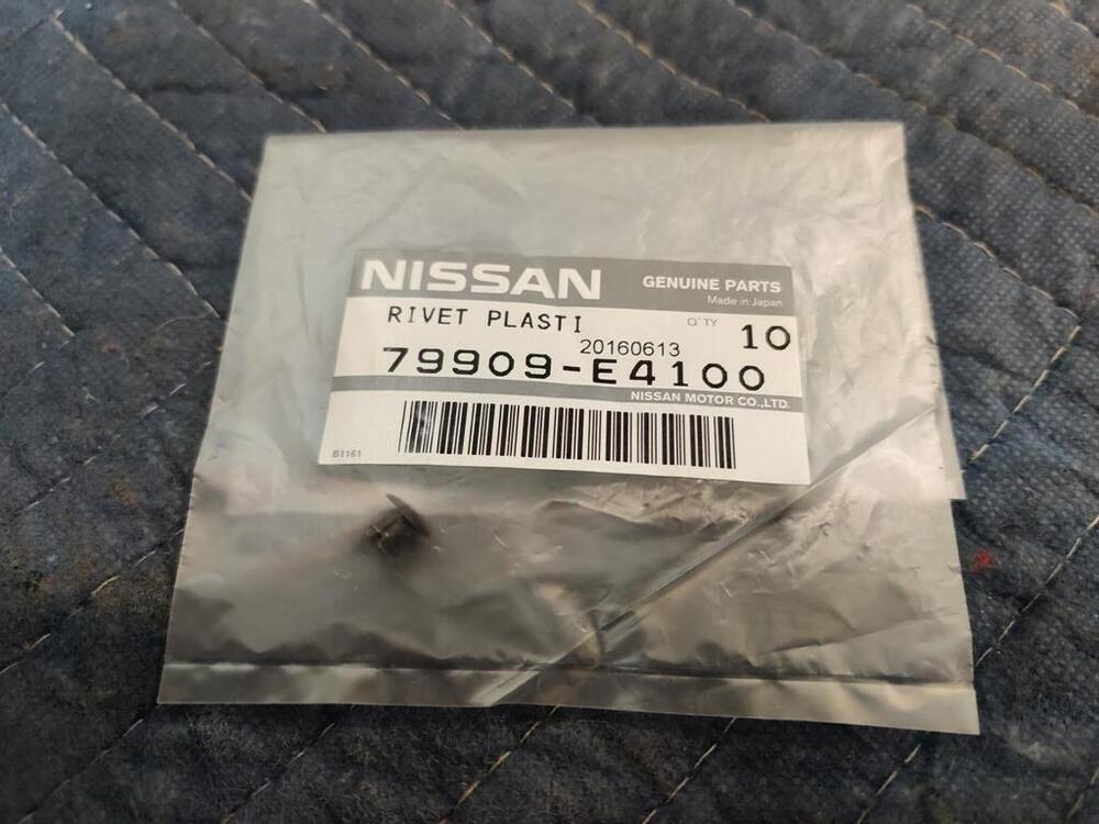
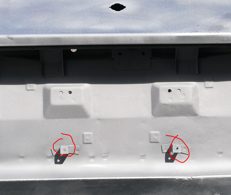
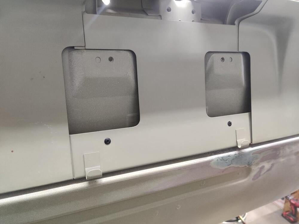
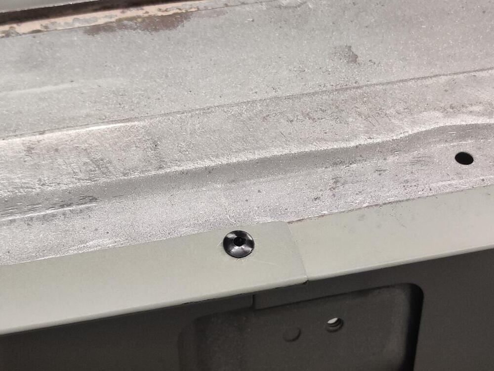
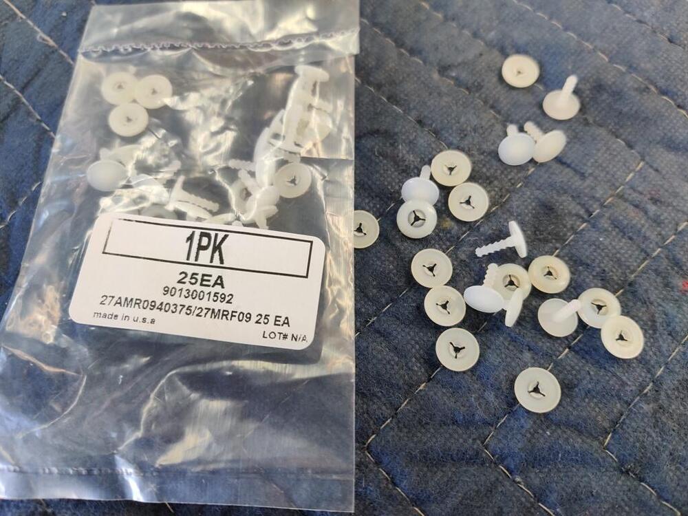
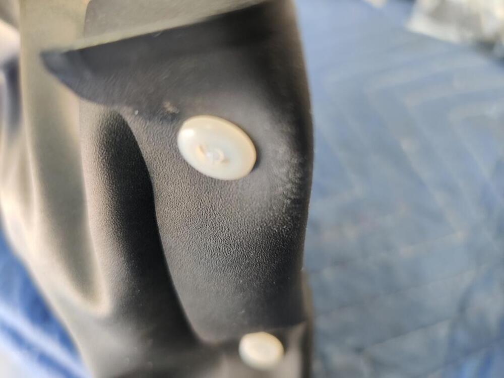
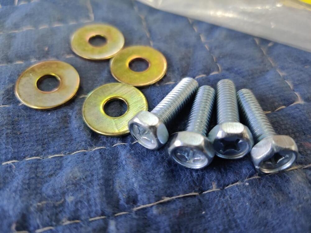
Yep. Also, I measure the outer diameter of them at .175" inches. They are similar to the clips used for the inside trim panels in that they utilize a small plastic shaft which is pushed into a hole in the center of the rivet. Pushing it flush with the top of the rivet expands 4 "fingers" behind the hole which is what grips the part into place.
-
I have some of the correct plastic rivets. They are quite small in comparison to the plastic rivets used on the interior trim panels. I will get some dimensions on them. I was able to source them new from Nissan within the last couple of years. These holes use the same plastic rivets, but you may not have those brackets anymore as they may only be on US cars for the US license plates.
-
Yes, thanks for the exposure to another source!
-
Steve Nixon makes a replacement also: https://www.240zrubberparts.com/product-page/240z-seat-adjuster-knob If you want the one you got there to be shiny like the original, you could probably wet sand and then polish it. Maybe fitting it temporarily to a shaft and spin that in a drill to sand and polish.
-
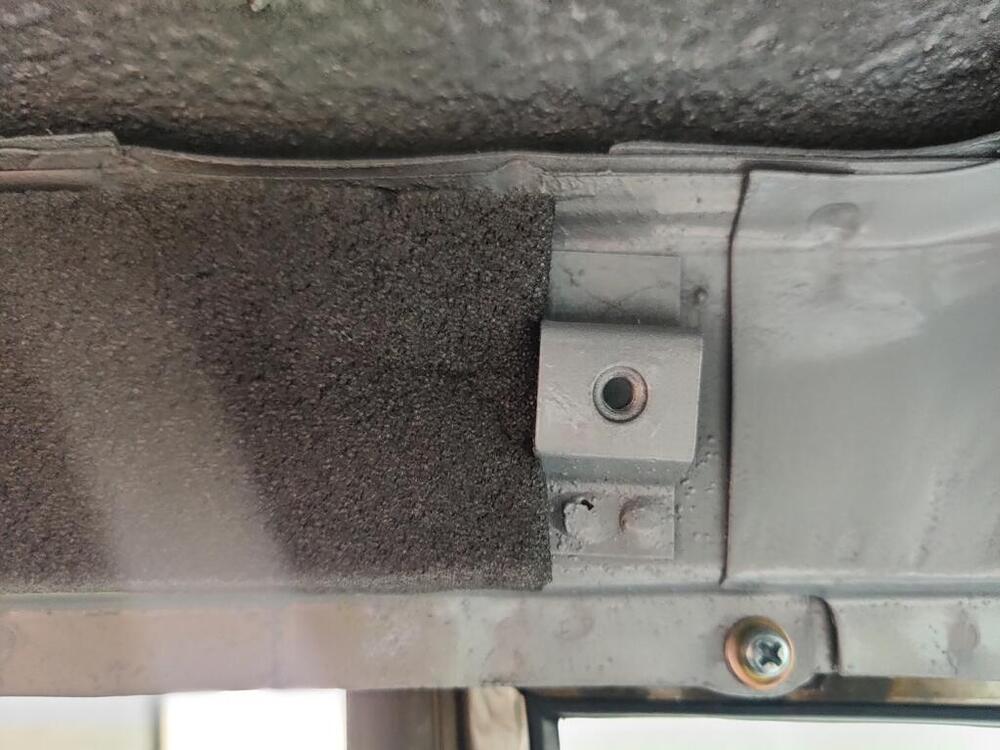
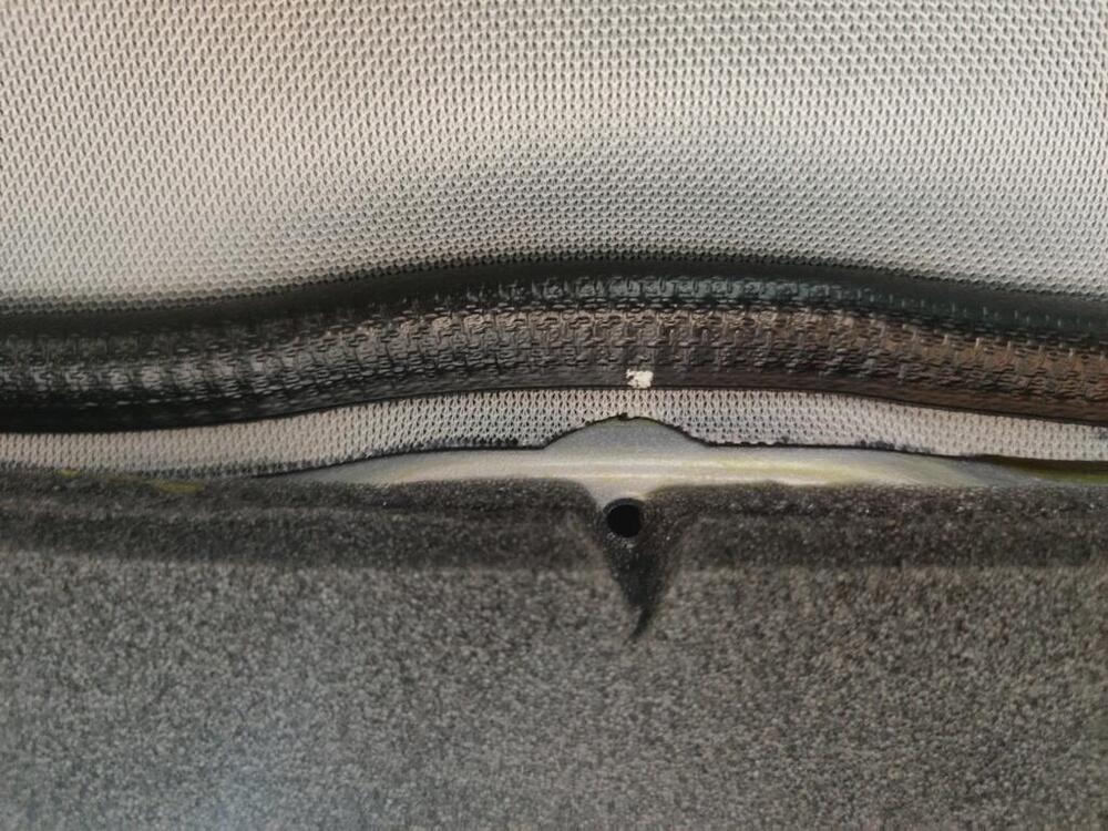
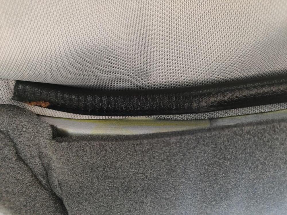
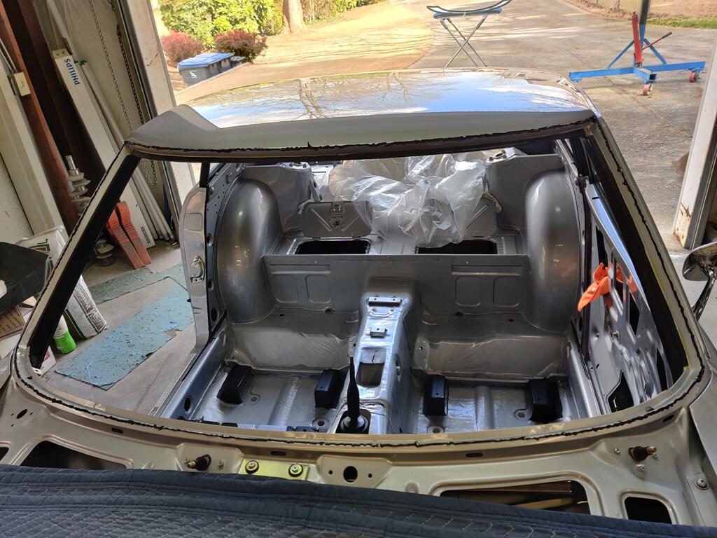
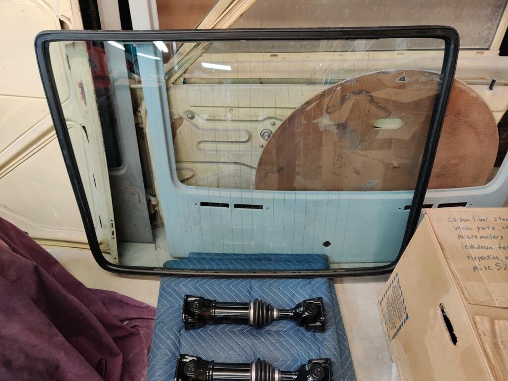
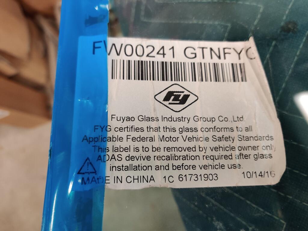
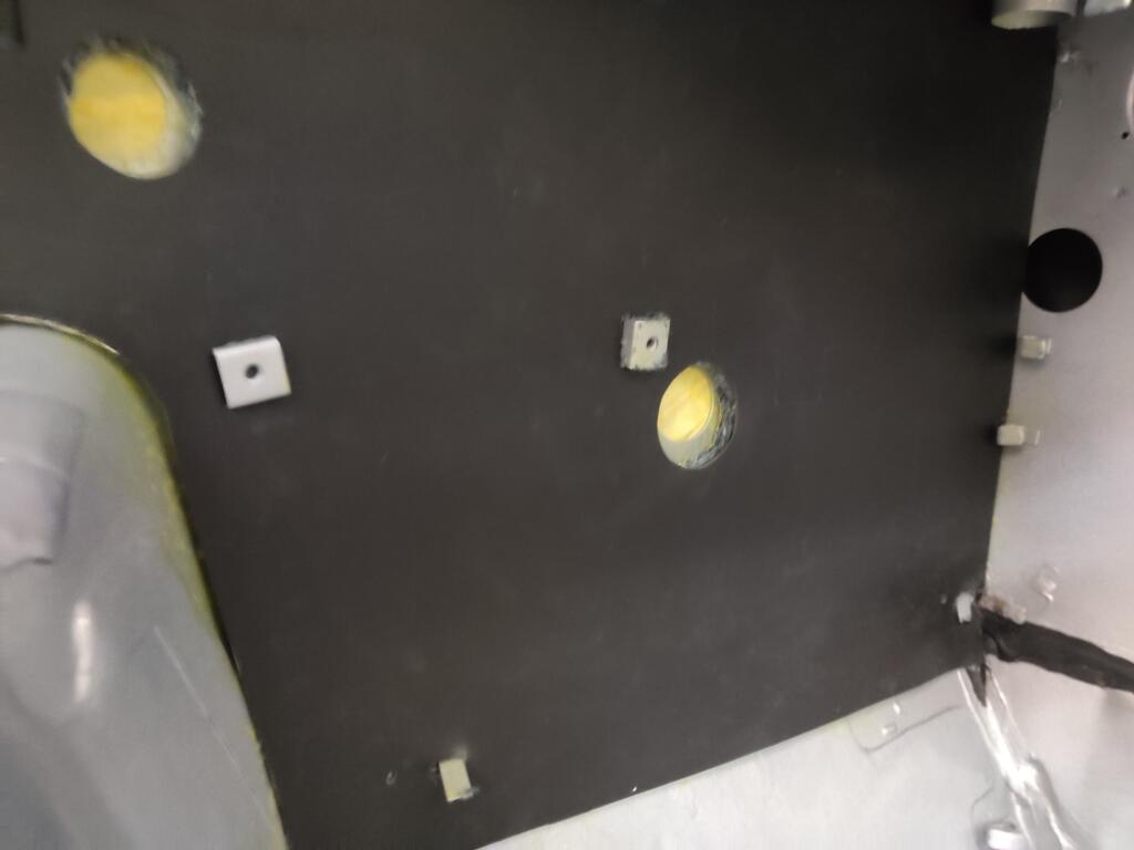
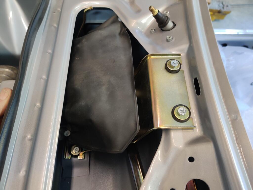
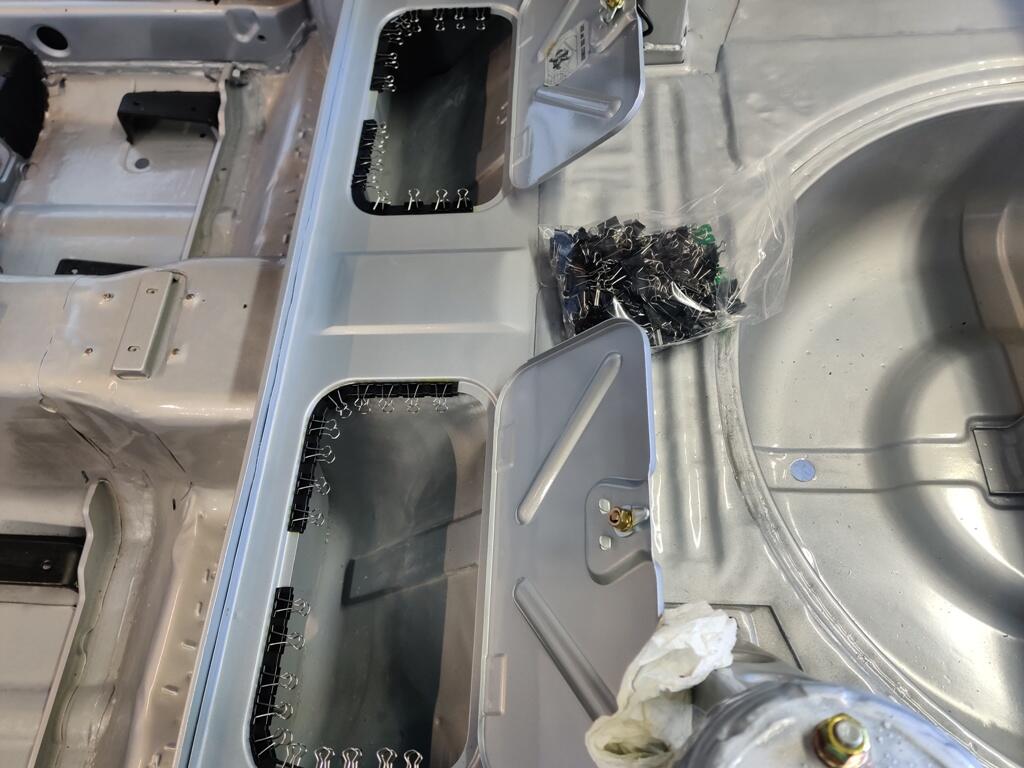
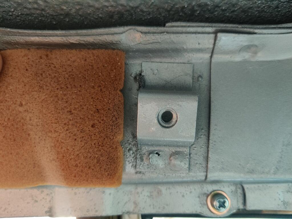
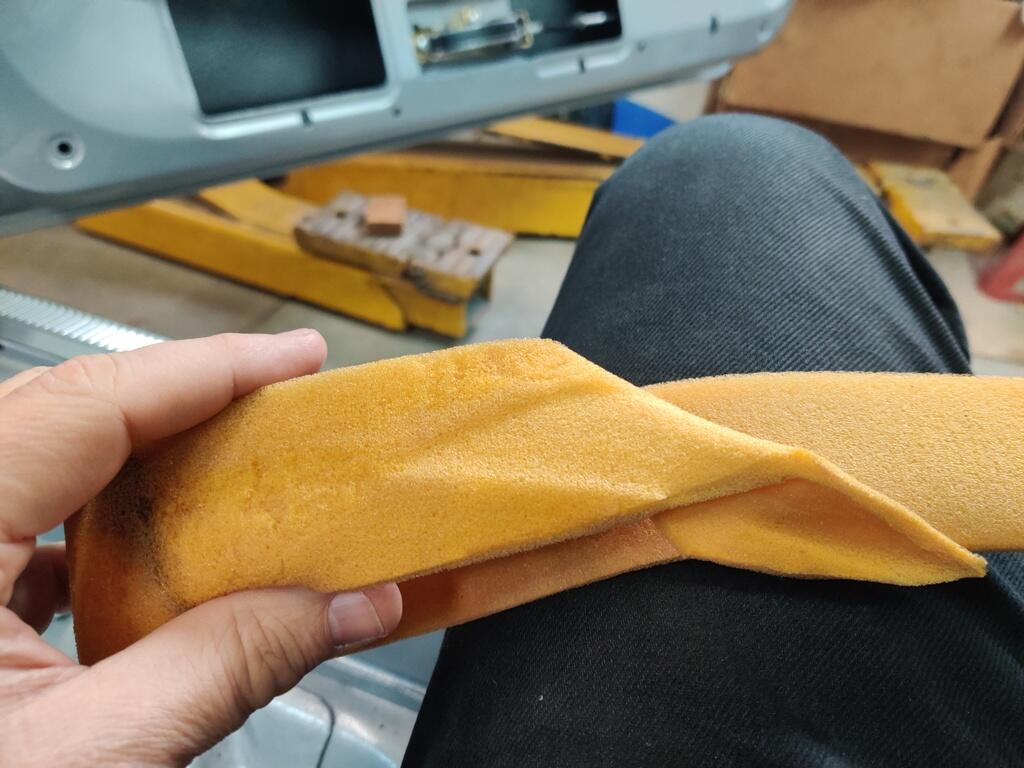
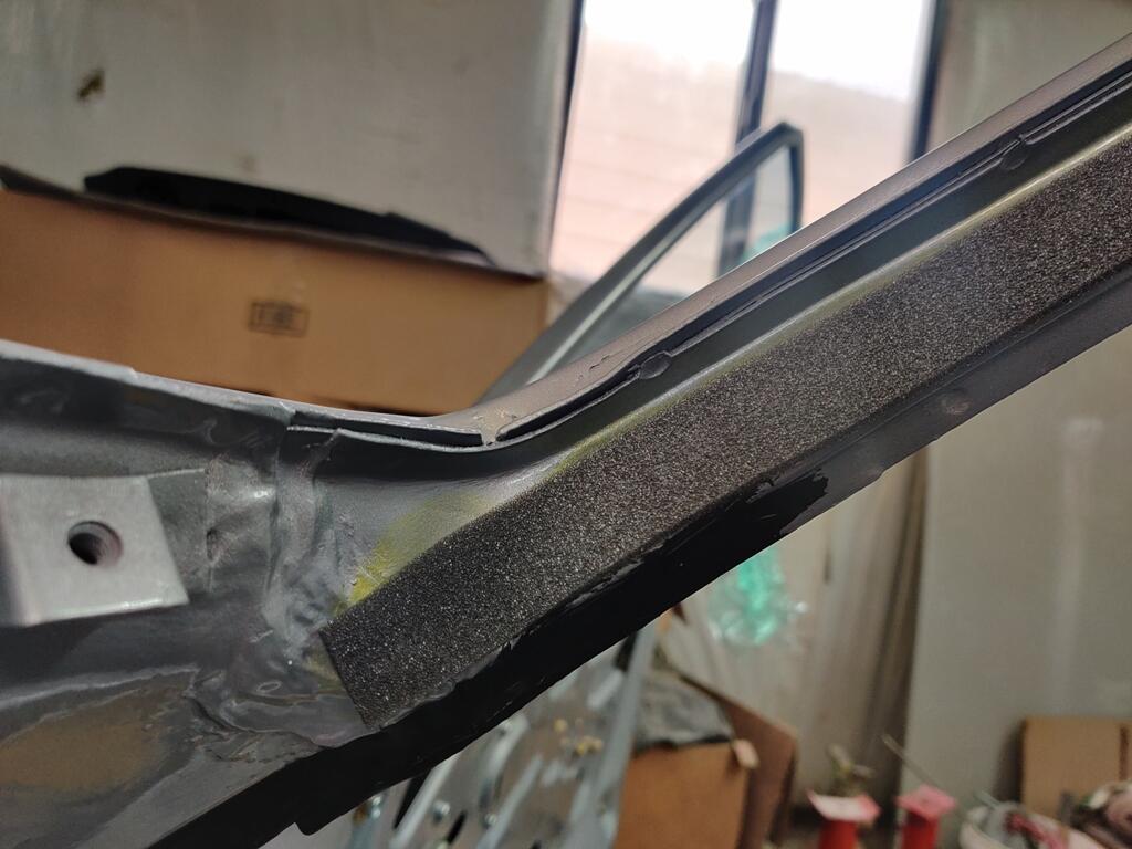
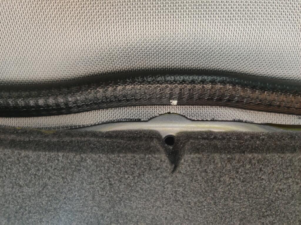
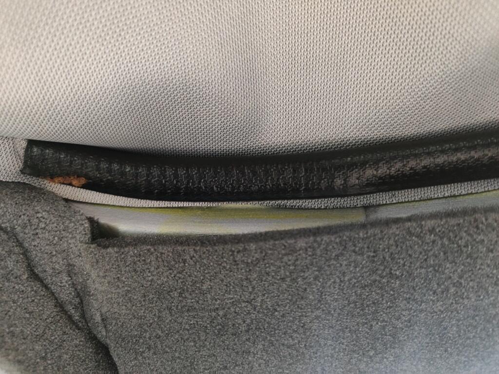
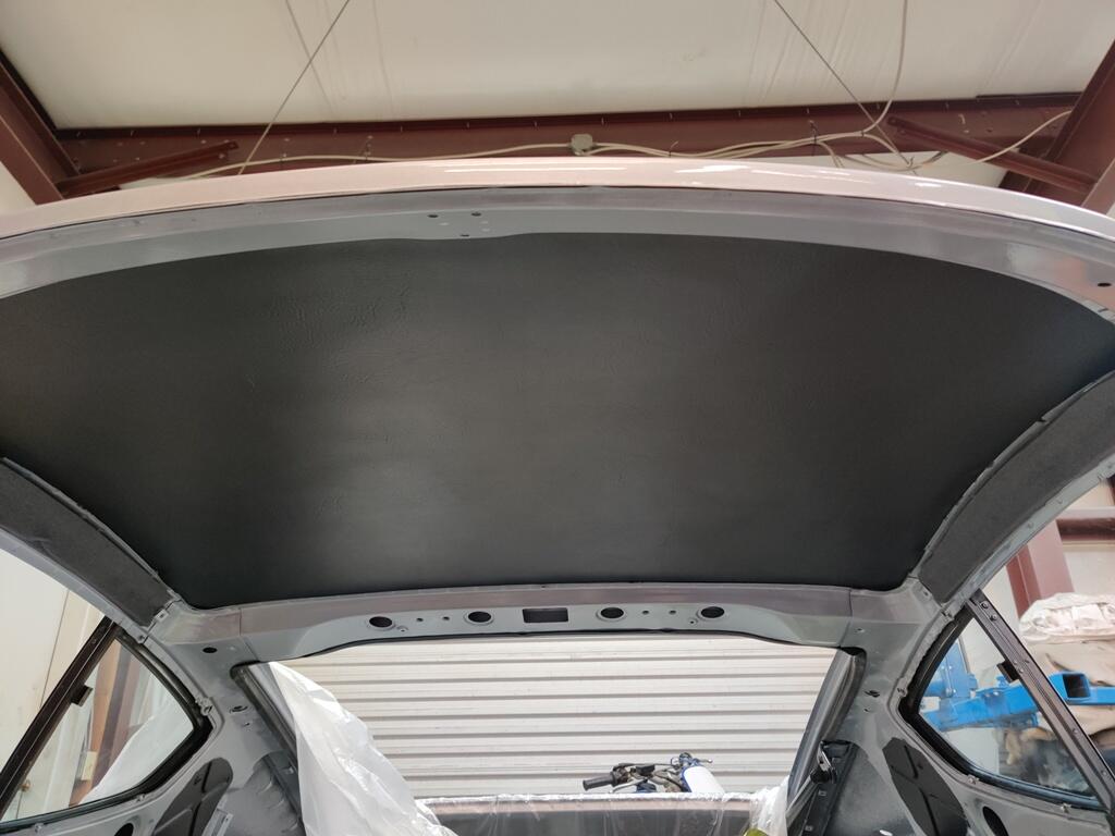
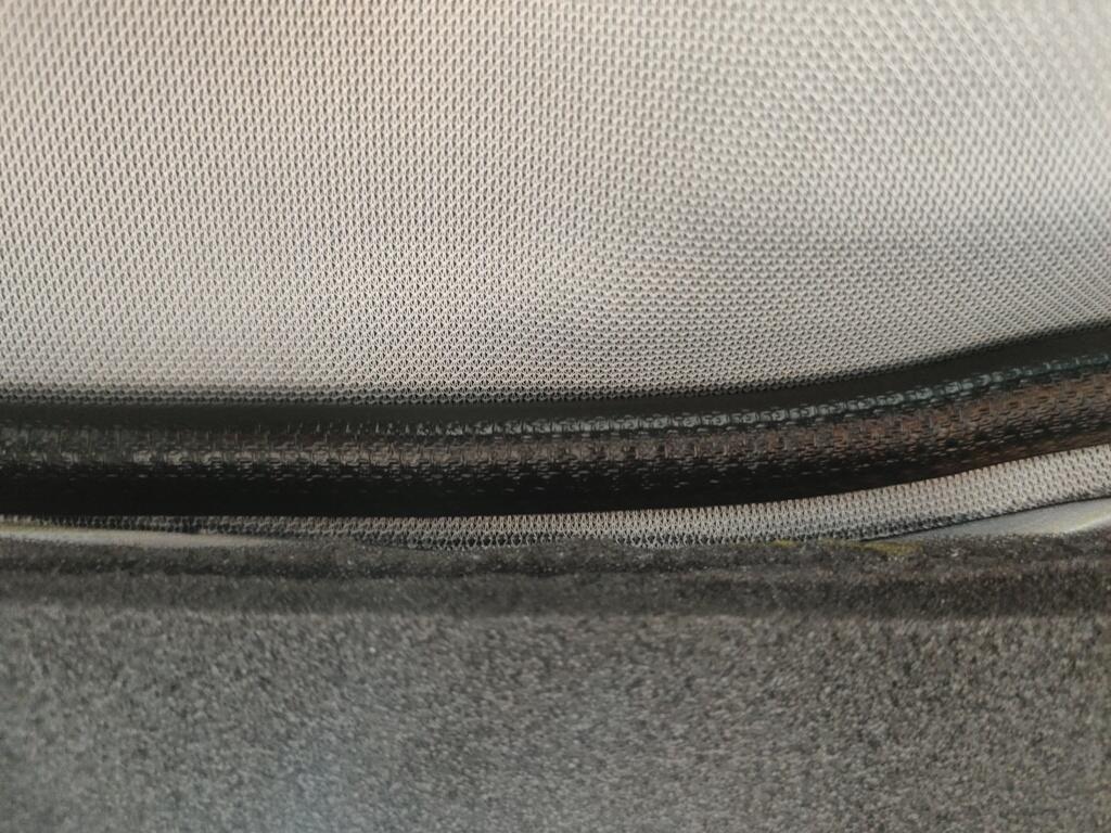
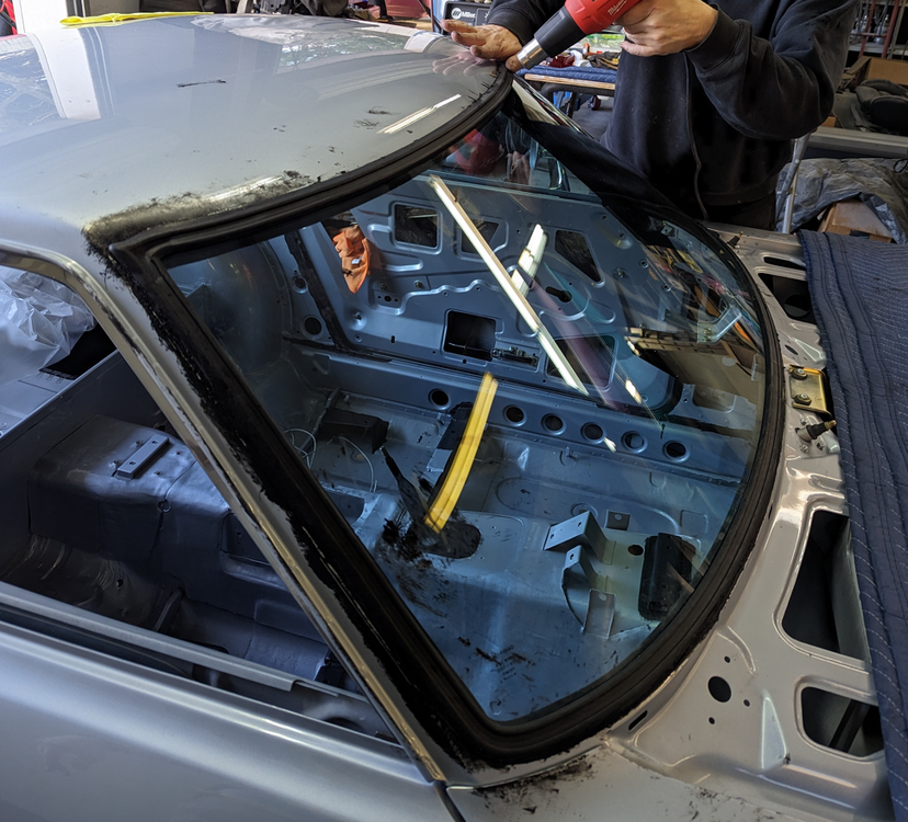
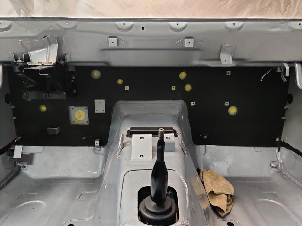
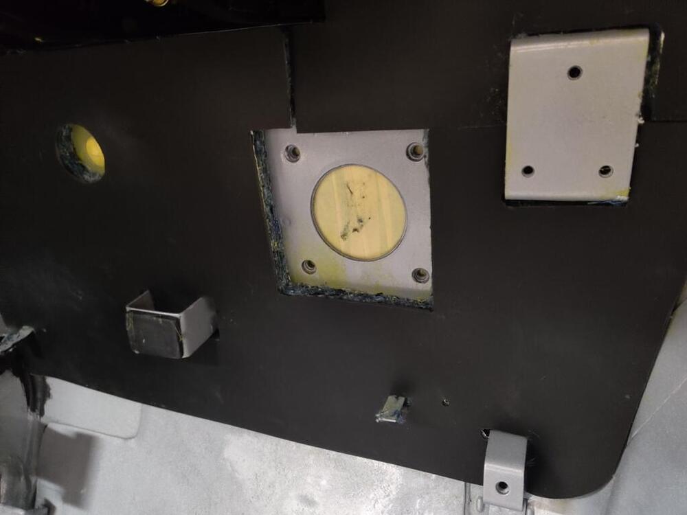
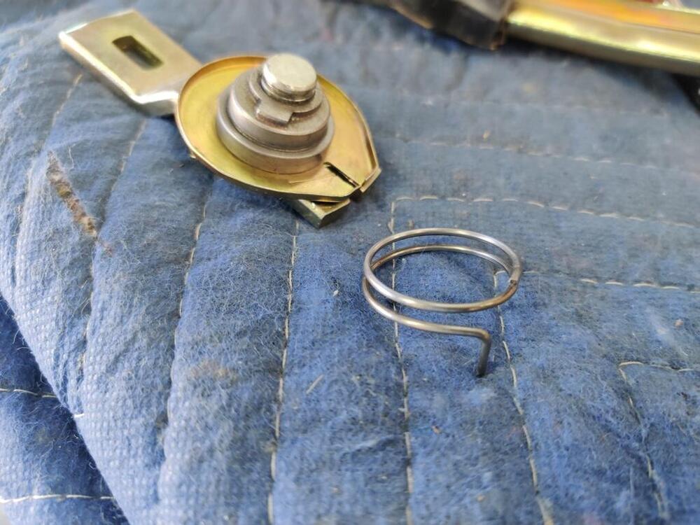
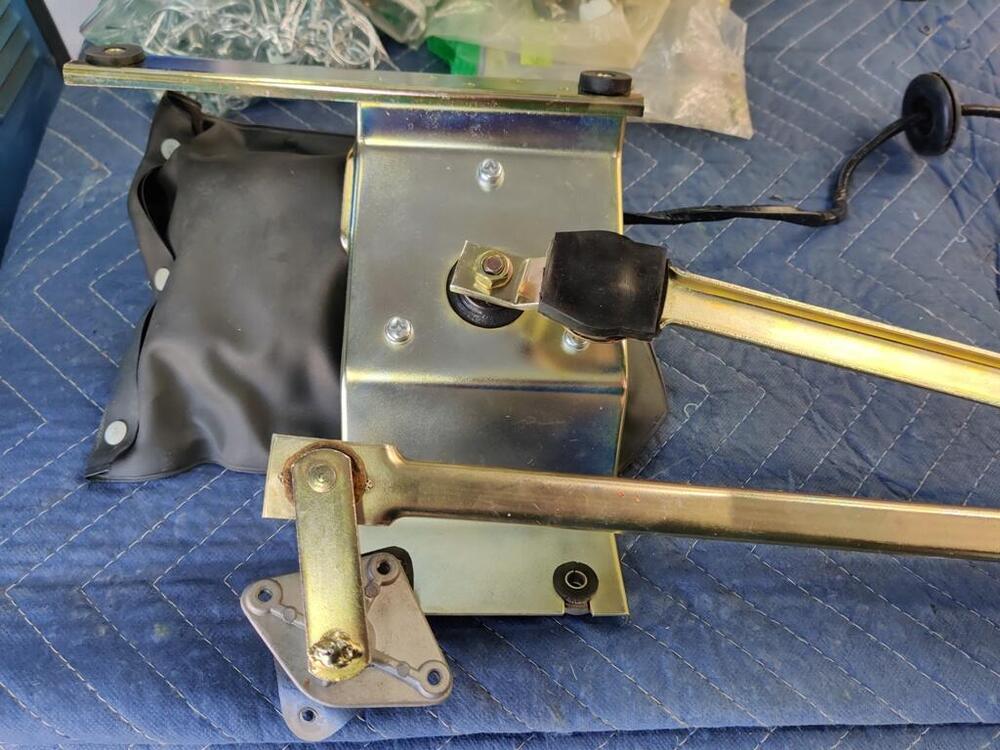
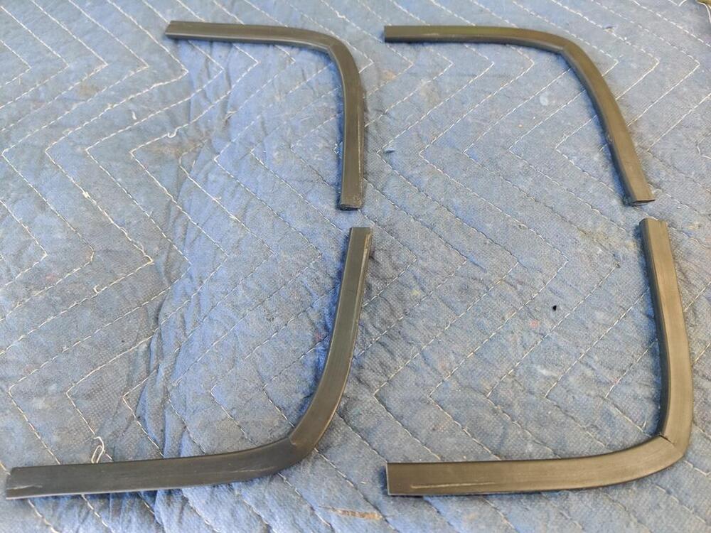
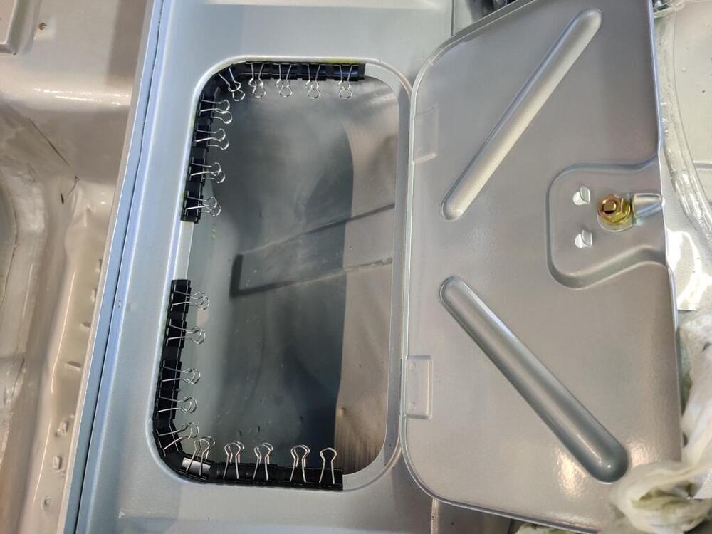
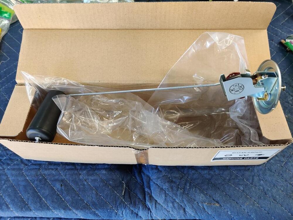
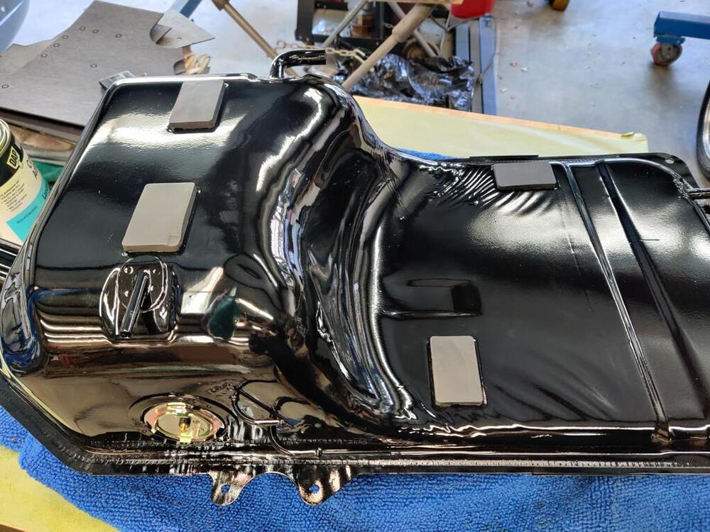
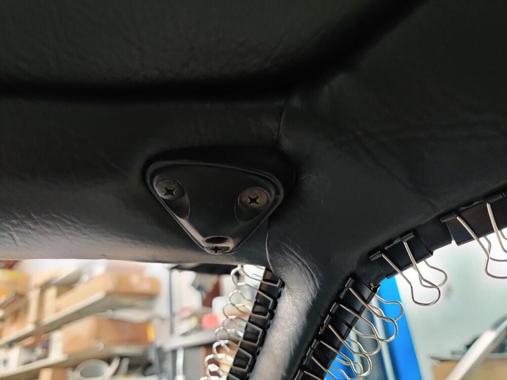
Yesterday, I completed the very difficult task of installing the vinyl A-pillar/side trims. I took my time. I found it helpful to examine the old ones very carefully while trying to get the new ones installed properly. I discovered that the quarter windows have to be out to install these properly. So, I had to take those back out temporarily. Like many things, it is a whole lot easier when you have done one. The second one was much easier and took much less time to install. The only part that didn't turn out perfect is where the side welting butts up against the header. I left a bit more vinyl material there than I should have. If I could do them again, I could get them perfect. But, it isn't worth spending all the time and effort to rip out these, cut new ones and do another install. I found the clips to be more useful with these because I wanted the vinyl to stick to the inside of the weld flange too. It sticks perfectly to the outside of the weld flange without the assistance of the clips. But on the inside, the vinyl is at an angle pulling away from the flange. The clips help it seat there. I had today off from work, so in addition to the usual weekend hours, I was able to spend another 6.5 hours on the car. 🙂 The rear hatch glass has been sitting in a corner waiting... for the scratch remover kit I ordered to show up, and for me to devote time to removing the scratches. The kit has arrived: I found out about it on Youtube. I was intrigued when I saw a video that showed removal of a deep scratch. I had used Eastwood's kit, and found that it was barely adequate to remove some light wiper marks from my BWM M3 windshield. That is not a fault of the product, but I did not realize until I saw this video that there was a product that could remove deep scratches. But, I did not choose to work on that today. Like the rear hatch glass, I cleaned my windshield and installed the NOS rubber weather strip on it. I bought the windshield a few years ago when I was finding it hard to source a windshield without the blue "stripe" of tint across the top. It was made in China, but appears to be a decent quality one. I am going to wait for a warm day and put the windshield out in the sun. I want the weather strip to heat up and relax in the sun before I attempt the install. I will do the same for the hatch glass. I had not yet shared pictures of the new firewall insulation installed. When I applied the vinyl to the foam for the new headliner, and while the contact adhesive was in the spray gun, I installed them. I think they turned out to be very nice. I was held up on finishing the installation of the windshield wiper motor and mechanism because I was searching for a suitable replacement for the plastic "push clips" that hold the wiper bag end together. I found these at McMaster-Carr and they turned out to work nicely. After snapping them together, I just use small clippers to clip the extra portion of the post off. Additionally, I came across a forum thread in which @Captain Obvious described the proper function of the wiper arms. I had no idea that the round spring that always breaks was responsible for changing the off/resting position. I saw where some had bent the end of the existing, broken spring, so that it has a new "tang" to fit into the slot. I modified my spring today (third pic). It works perfectly - I can rotate it with ease in one direction and when I rotate in the reverse direction, I can feel the spring acting like a "one-way clutch". It grabs the eccentric piece you see and rotates it, which because of the offset, changes the length of the wiper arm assembly just a touch. This is what alters the "parked" position of the wipers to something just a bit lower than that of in operation mode. Cool! I believe this is the correct way to assemble the linkage to the motor, but I will leave the wiper off when I turn on the wipers to test them. Thanks for the tip @emccallum! Next, I moved over to gluing some more parts. Wiping the tool door cushions with lacquer thinner cleaned them up nicely. Then, I used a small brush and the same contact adhesive to install them. In this case, I didn't put adhesive inside the groove of the rubber cushions, as that would have been difficult and would have made a mess. Because I only put adhesive on the metal, I used the file clips to hold the cushions in place until the glue could set. While I had the adhesive out, I also glued the rubber blocks to the gas tank and installed the new gas tank sender unit:


-
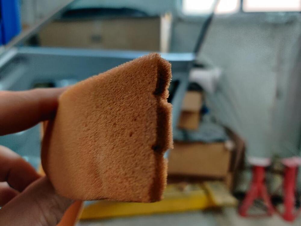
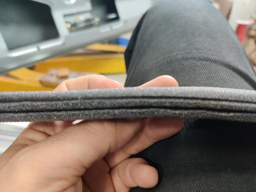
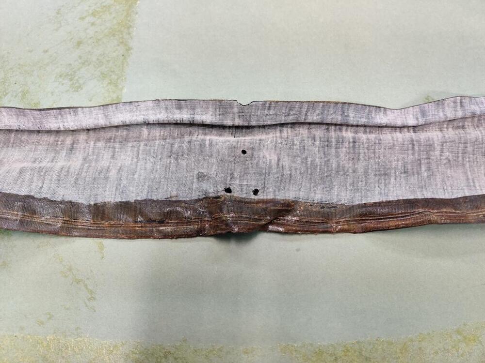
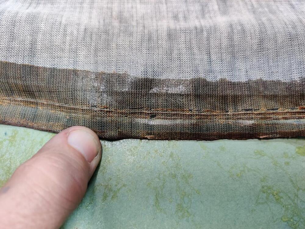
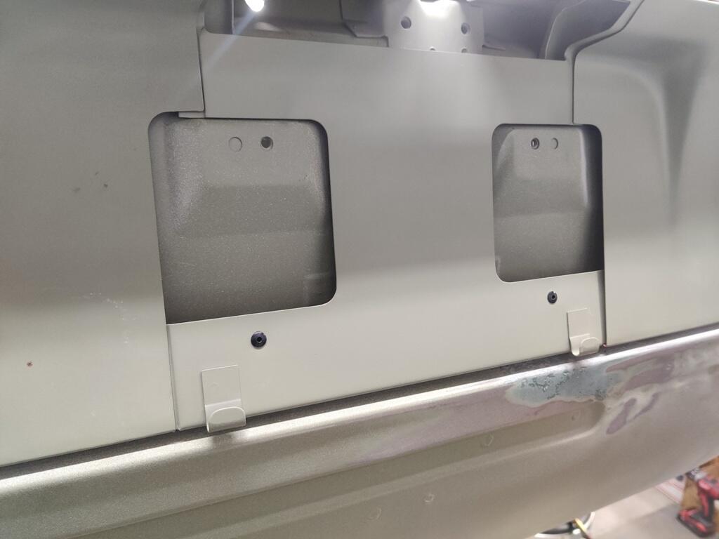
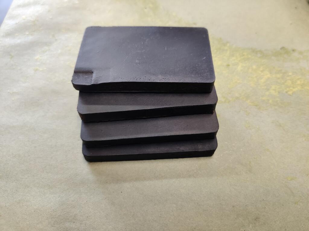
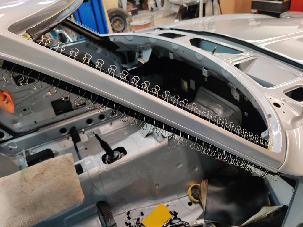
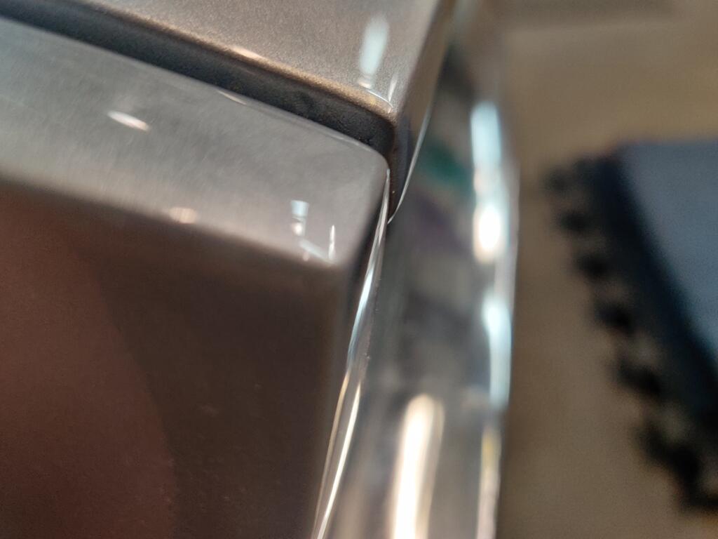
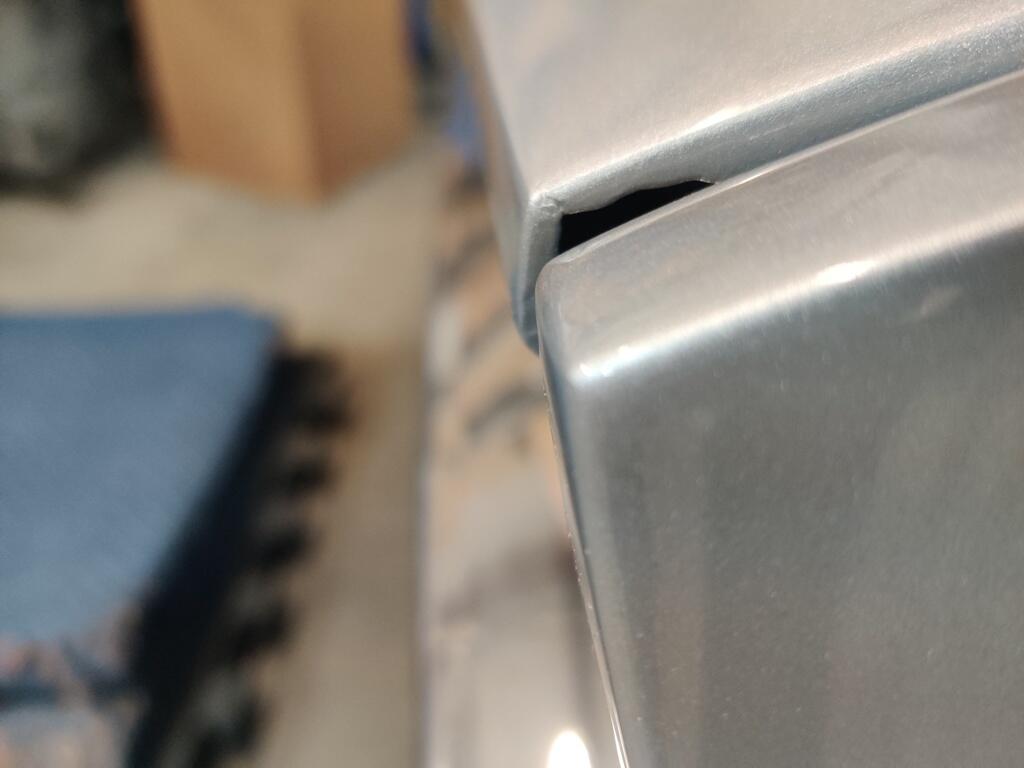
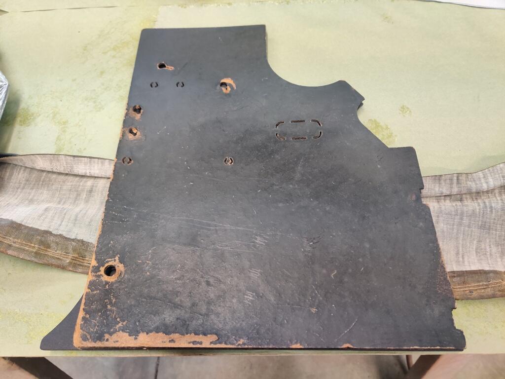
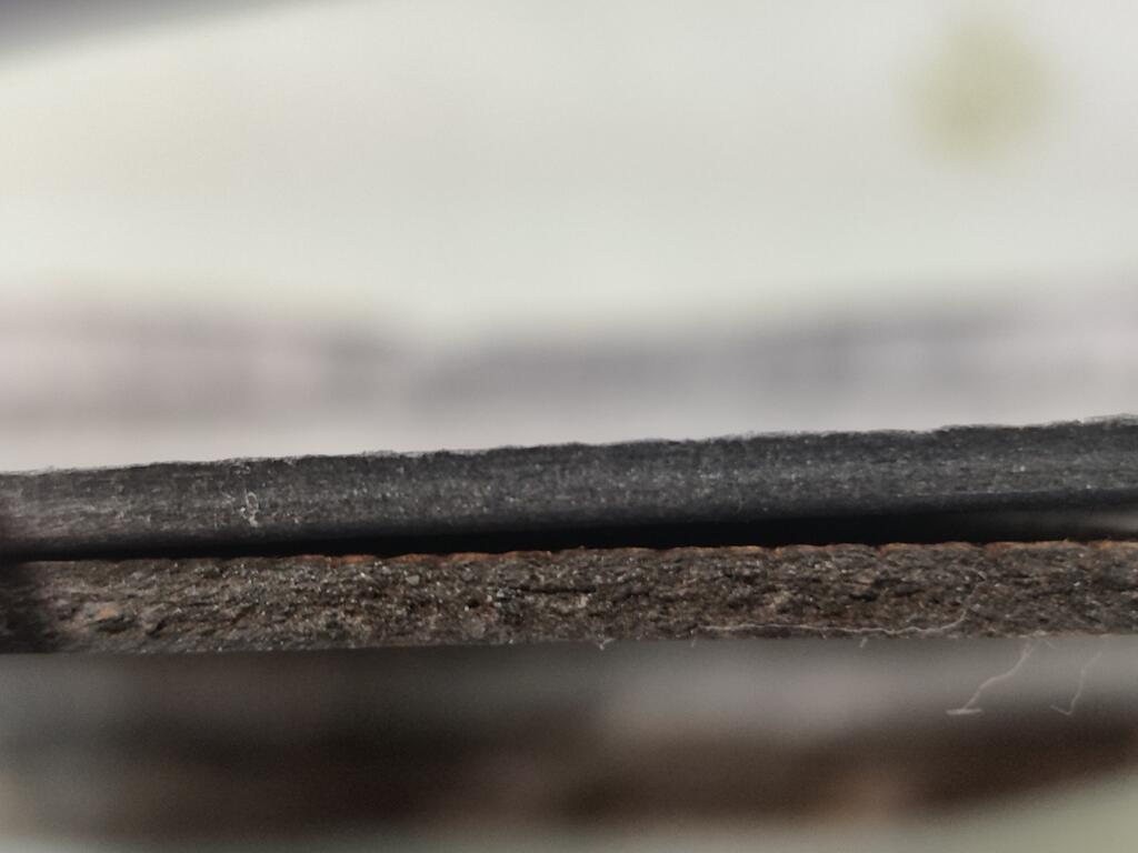
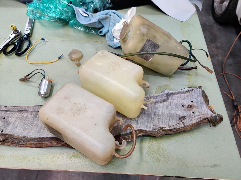
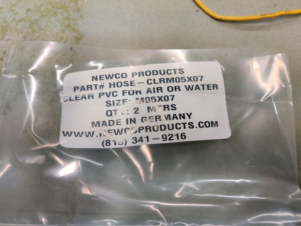
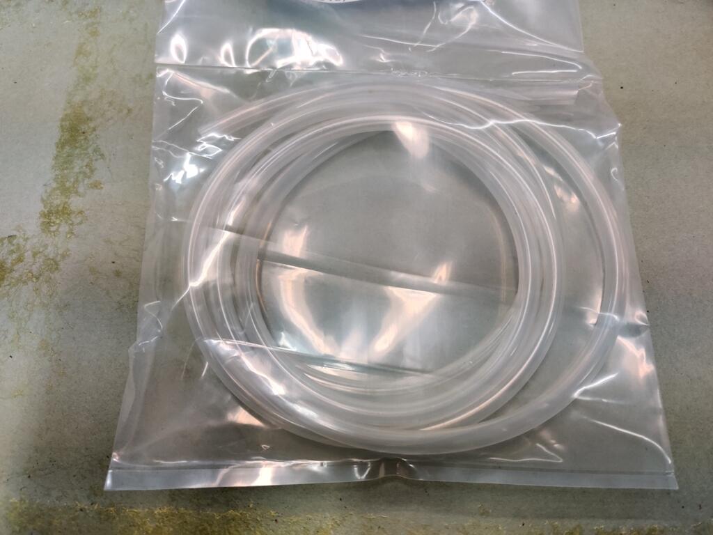
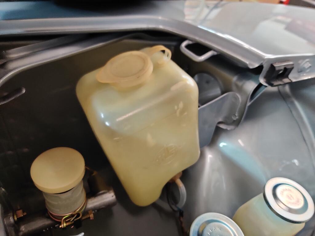
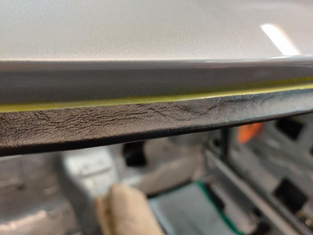
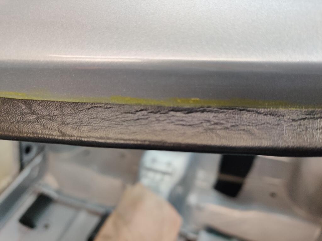
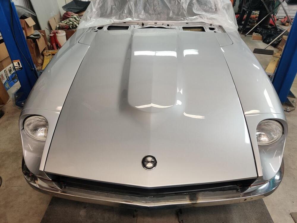
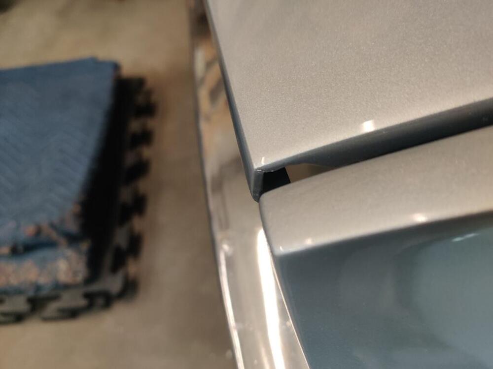
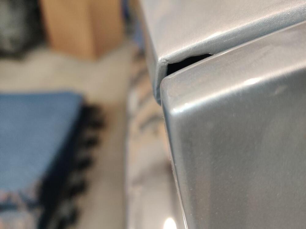
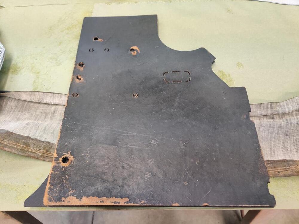
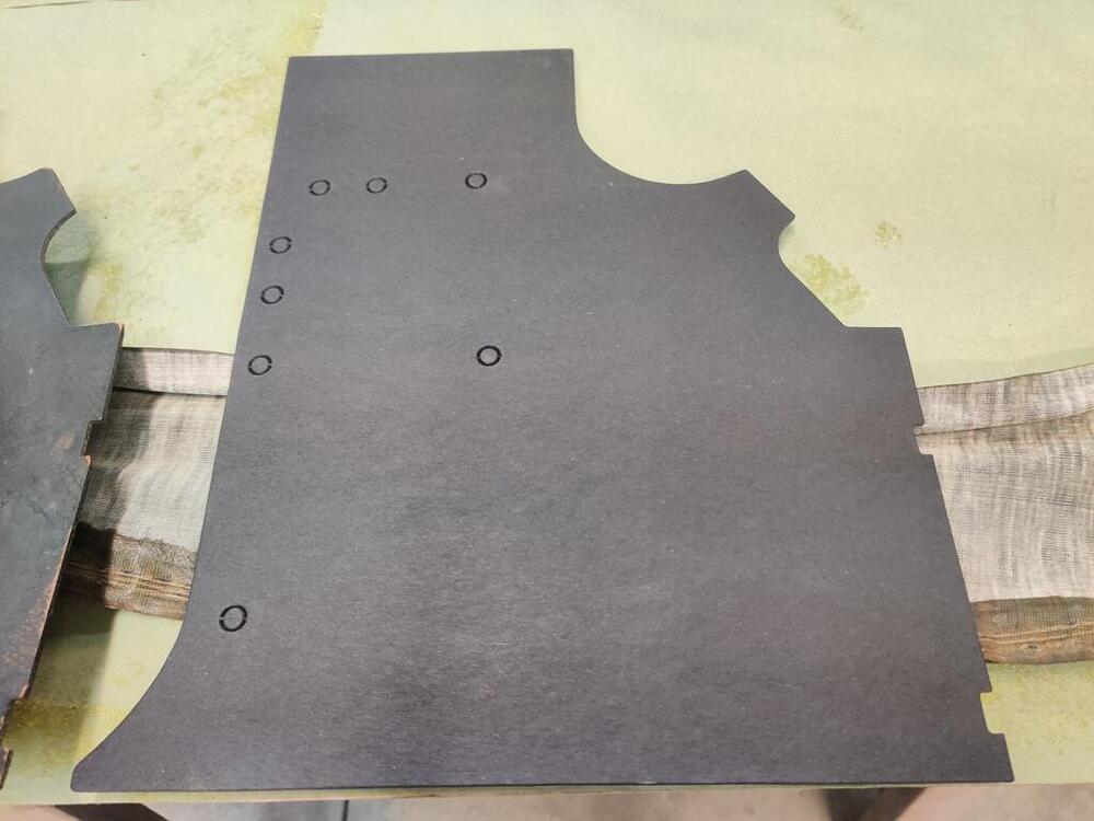
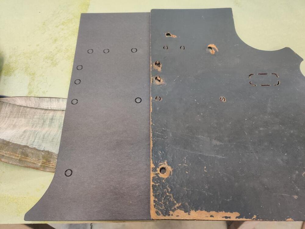
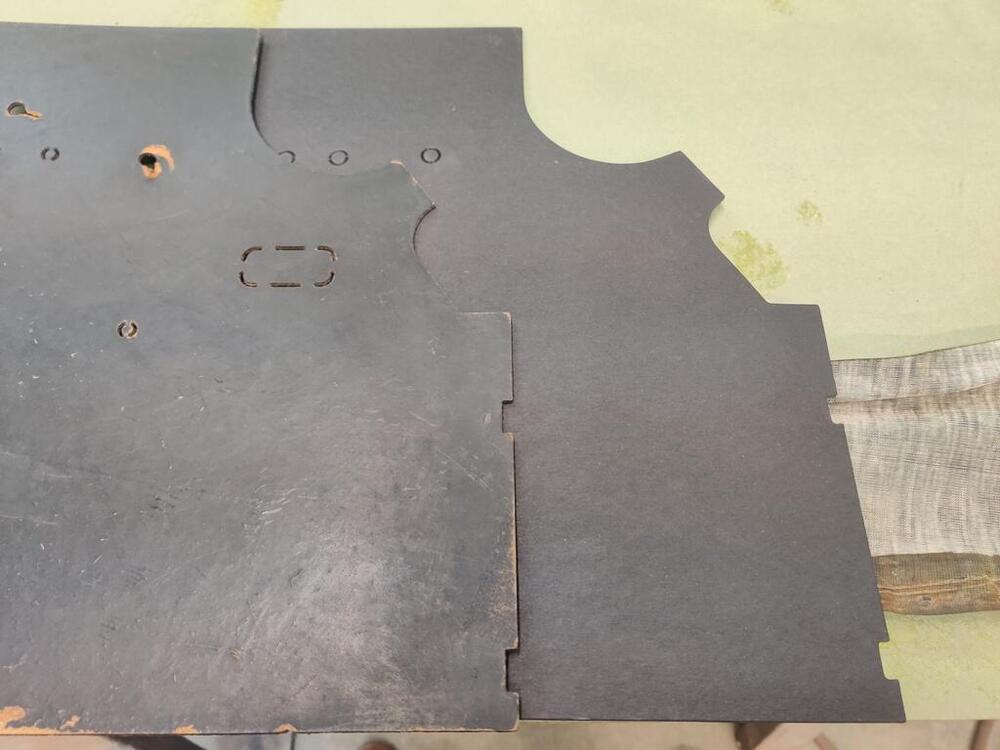
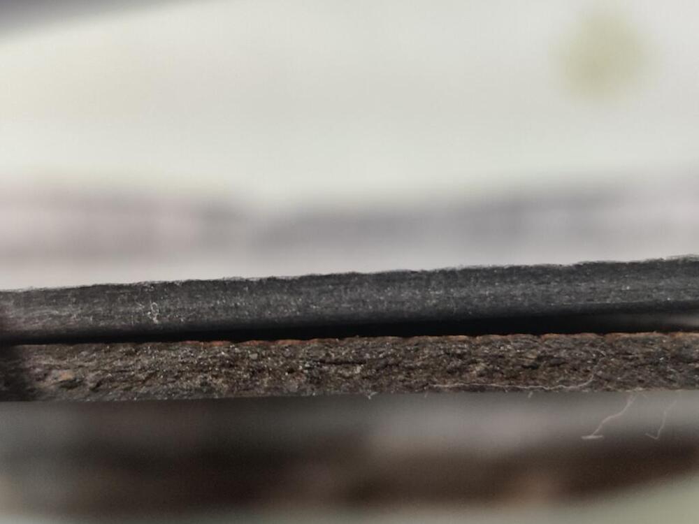
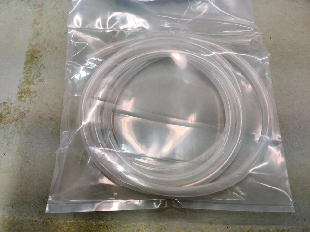
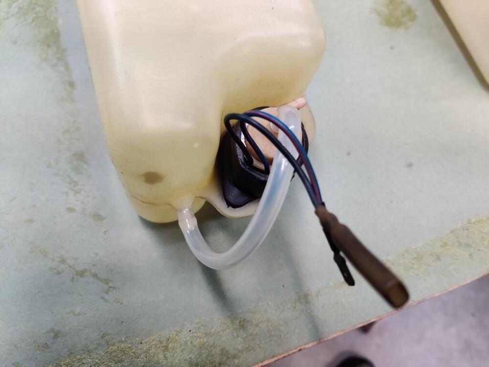
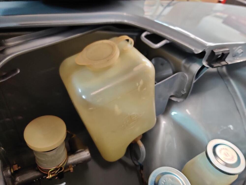
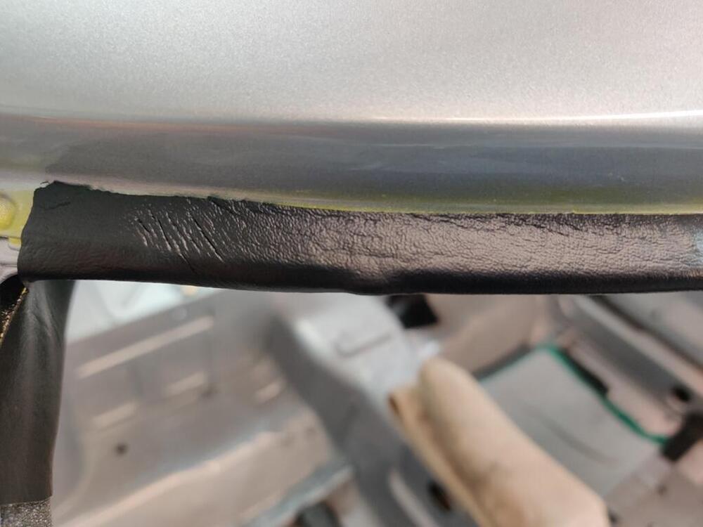
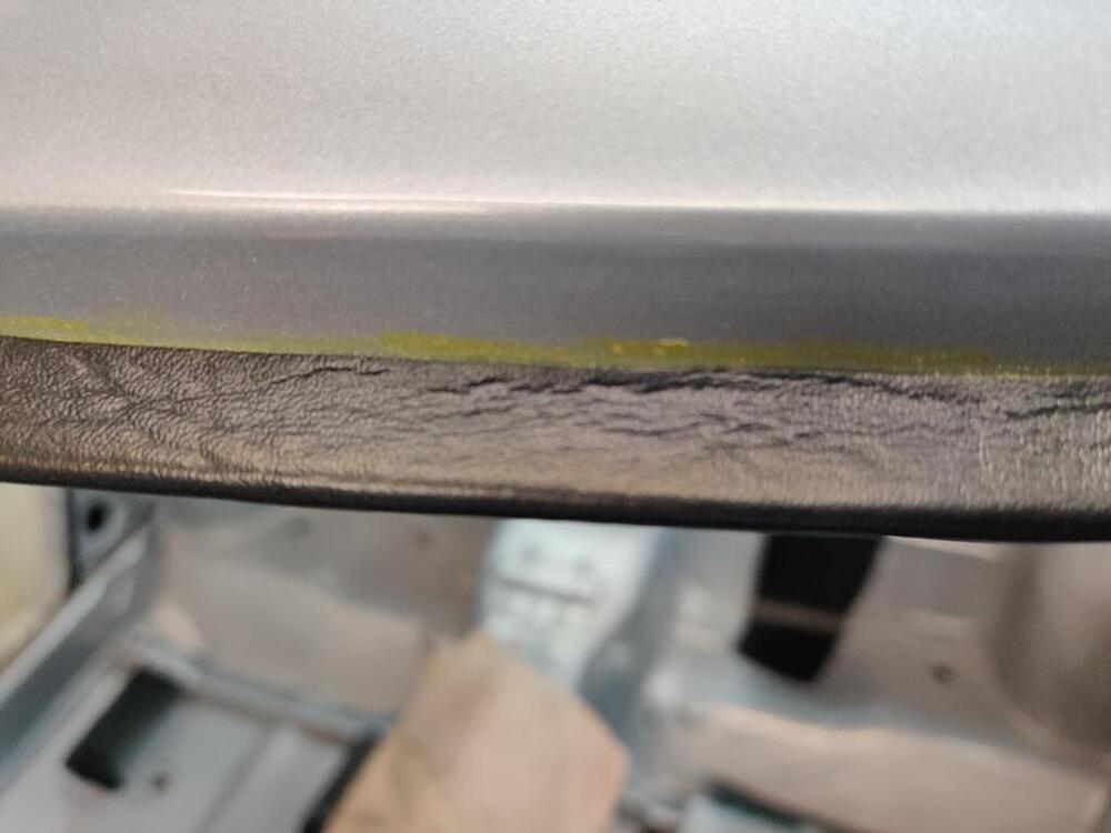
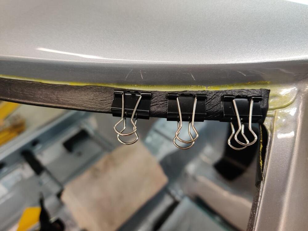
It was with some dread that I installed the hood onto the car. Flashback to when I was scrambling to get the car finished for transport to the body shop in February of last year, and when I installed the hood, I saw that I had some panel alignment issues. I won't rehash all of it here, but I provided details in the document I wrote up for the body shop. This should have been a checklist for them. But clearly, they did not do several of the things I pointed out for them. Quoting from my write up: "The hood: The front lip, at the very left corner edge of the hood, is bent outward a touch. I didn’t notice it until I started fitting the hood for the last time. I tapped the front lip at this corner with a body hammer to move it back a touch to align with the left headlight housing and the resulting movement caused some small chips of the primer to flake off. The left front corner of the hood will need some attention - possibly some more tapping with a hammer and possibly some primer application. The hood has some scratches in the surface that will need attention." Well, while the scratches in the surface of the hood were addressed, the corner of the hood got ignored. The front left corner still sticks out a bit, and at the top corner, I can see where the primer chipped. So, this is just another reminder that "next time", I will not be leaving anything to anyone else - I will do it all, and I will do it right. With this type of thing, my frustration level is high. I still need to massage the fit of the hood a bit, but I decided to move to other things for now. I unpacked the new kick panel covers. I bought these from Motorsport Auto. They are "ok". They are not quite as thick as the originals... even when measuring thickness at the top edge of the old ones where no water has gotten to fiber board and caused it to swell. There are slight differences which you can see here: Second pic shows thickness of the top edge - old one is on the bottom. Next, I pulled out my collection of windshield washer reservoirs and pump motors. I sourced new windshield fluid hose from a company called Newco (see the tag for sizing info). I used a clean rag and lacquer thinner and some #0000 steel wool dipped in lacquer thinner to clean the outside of the reservoir. My pump motors were seized. I dis-assembled the first one, but there was no saving it - there was too much corrosion. The second one was in much better condition. Dis-assembly and reassembly was enough to get it running nicely. It may not last long in service, but we'll see. The last thing I did today was glue the front edge of the header vinyl. This contact adhesive is magical: Though I bought a bunch of the folder clips you see in one of the pictures here, I was amazed at how quickly this adhesive worked to secure the vinyl to the weld flange. I brushed it onto the backside of the vinyl and on the top side of the weld flange. I let it dry for about 4 minutes. And when I pulled the vinyl toward the windshield opening, I tugged on it pretty good. Just touching the vinyl to the forward edge of the weld flange... was enough to hold the vinyl at the tension I had put on it. It was wild. I then folded the vinyl over around that front edge and pushed it onto the adhesive on the top surface of the weld flange. It stuck and didn't move. I didn't need to use the file folder clips. It just stuck. I used my Exact-o knife to cut the excess vinyl off at the point where the weld flange ends: I put some clips on in the corner, "just in case", but I am sure they were not needed. This adhesive is wonderful and a joy to work with.


-
Just Dashes has been in business a long time and has many happy customers. I see that the before state of your dash was not that bad - the cracks are not very large. When the original pad has huge, deep cracks and has "expanded" in size, I think repairing it by grinding down the old foam and layering new on top is not a great idea. Here is a video from their website.
-
Sorry this happened - I can imagine how you felt when it happened, and how you feel now. Regarding the best option for dashes, I believe Vintage Dashes is the best option. When I bought mine, in came in a box via UPS/Fedex. You have to re-use your metal frame, but removing the old and mounting the new on the frame is not difficult. I don't recommend Just Dashes. They repair the existing dashboard. They retain a lot of the original foam which is old and brittle. And, if the dash has large cracks, the "pieces" have moved somewhat from the their original locations when the pad was all one piece. I had one done by them years ago and it ended up having fit issues around the glove box door and being a tad oversize... with the gauges fitting extremely tight. I feel like the result would be questionable at best for a pad that is cracked severely. And, I think they are even more expensive than Vintage Dashes. Garrett
-
Did they swap to the 3.545 and tell you after the fact when the payment was due? I would be upset if that happened. I would have liked to attempt to source a gear set before having them assemble it.
-
Nice - had no idea these existed. @Av8ferg I know you said you are looking to replace it, but the clicking... and banging on it with a starter... could just be the solenoid. Finding one at a suitable price and the work to replace it may be more than you want to take on - I understand. Having rebuilt my own starter not long ago, I realize that there is a certain amount of work that goes into rebuilding them, and assuming that was done... it might be a waste to chuck it without cracking it open to have a look. Or... it might be wise to just move on. It is nice to know that these new options exist.
-
Facebook. In their infinite wisdom, they make it hard to copy a link.
-
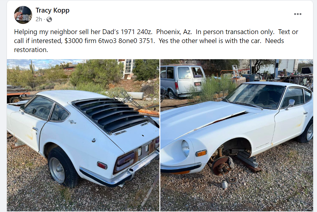
May already have a buyer in line - but this is a killer deal: 4XXX VIN, white on black. Appears to have original radio, early brake rotors, valve cover, steering wheel. Appears to have little rust. Appears to not have accident damage. Key parts of original interior are there but possibly in rough condition (center console, seats, ash tray, etc). $3000 - looking for in person transaction in Phoenix AZ.

-
I have found many things in your build thread to be helpful! I will look through again for that. Thanks.
-
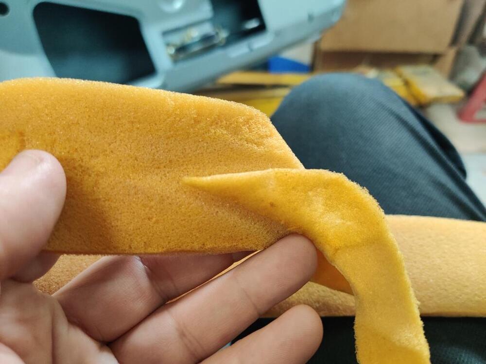
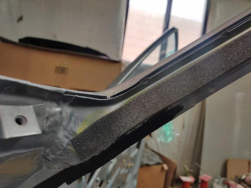
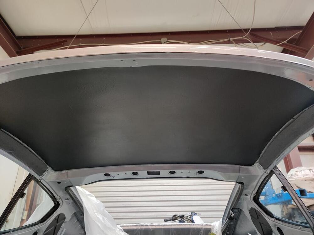
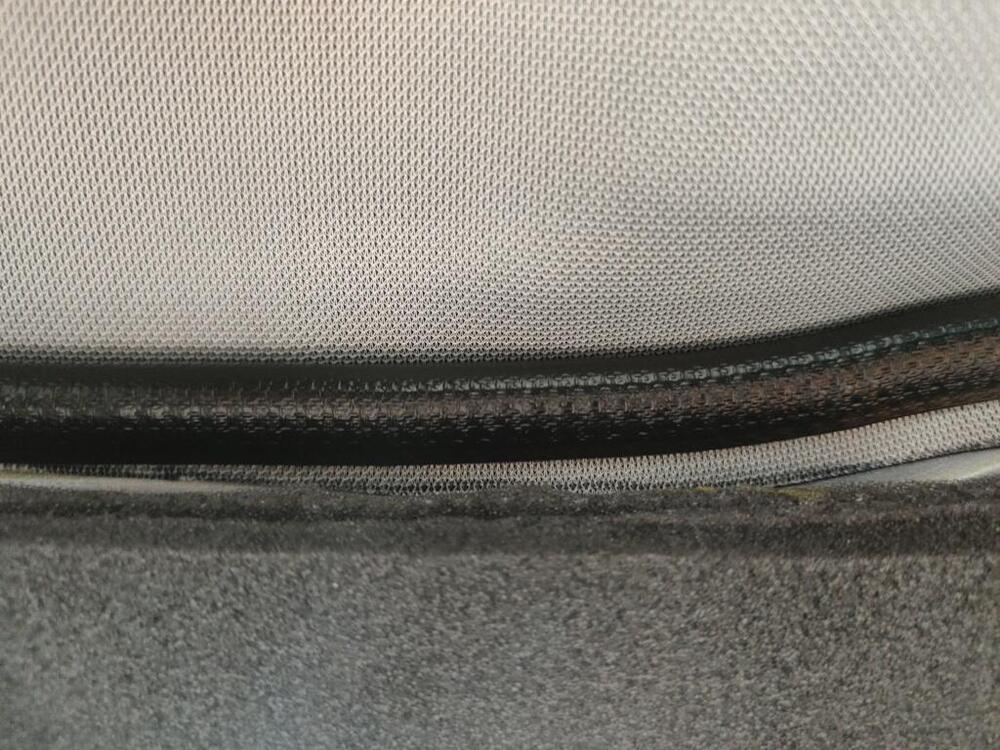
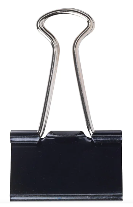
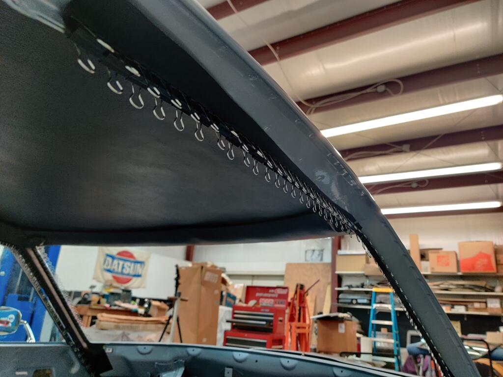
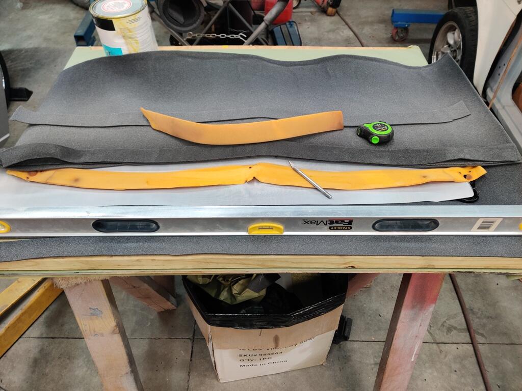
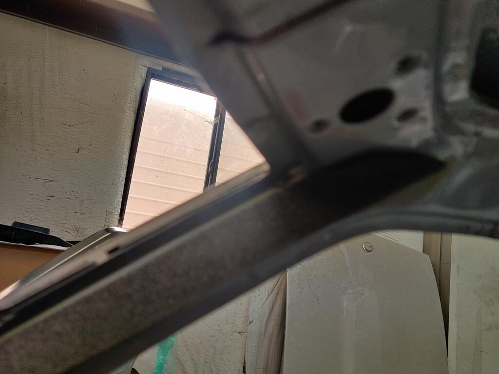
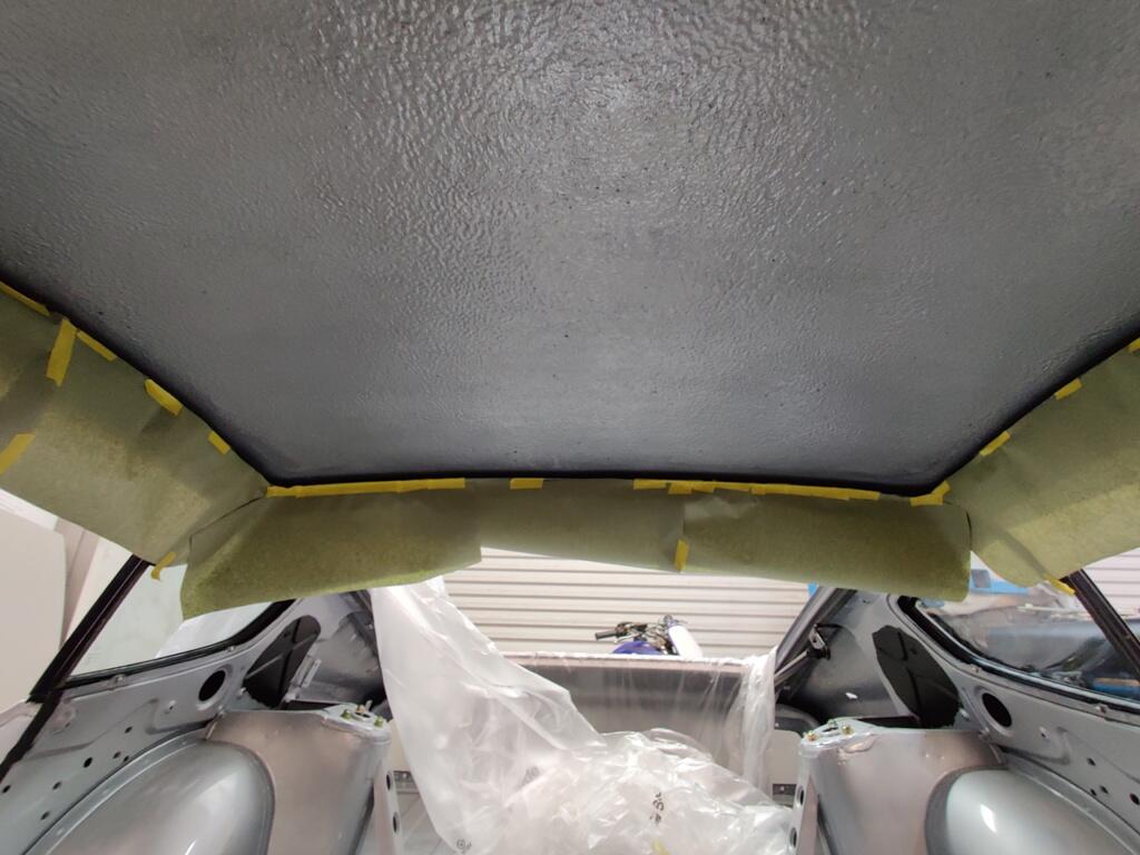
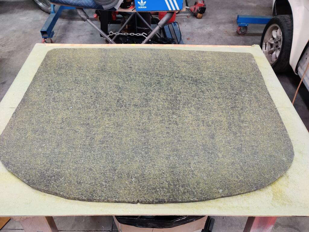
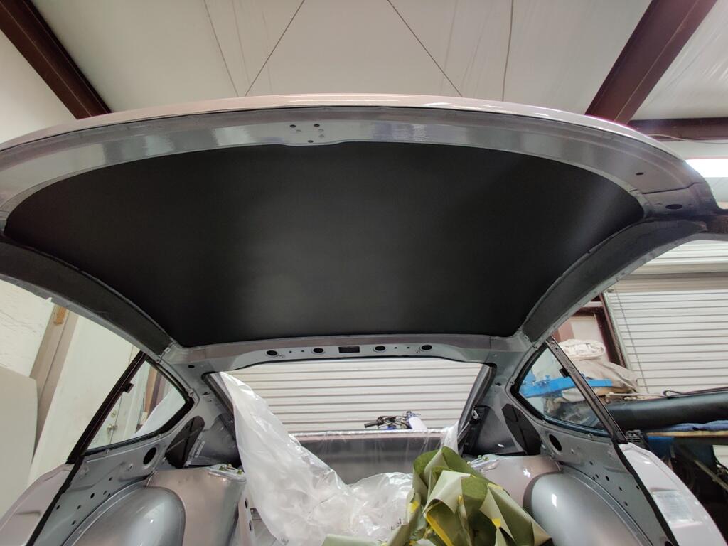
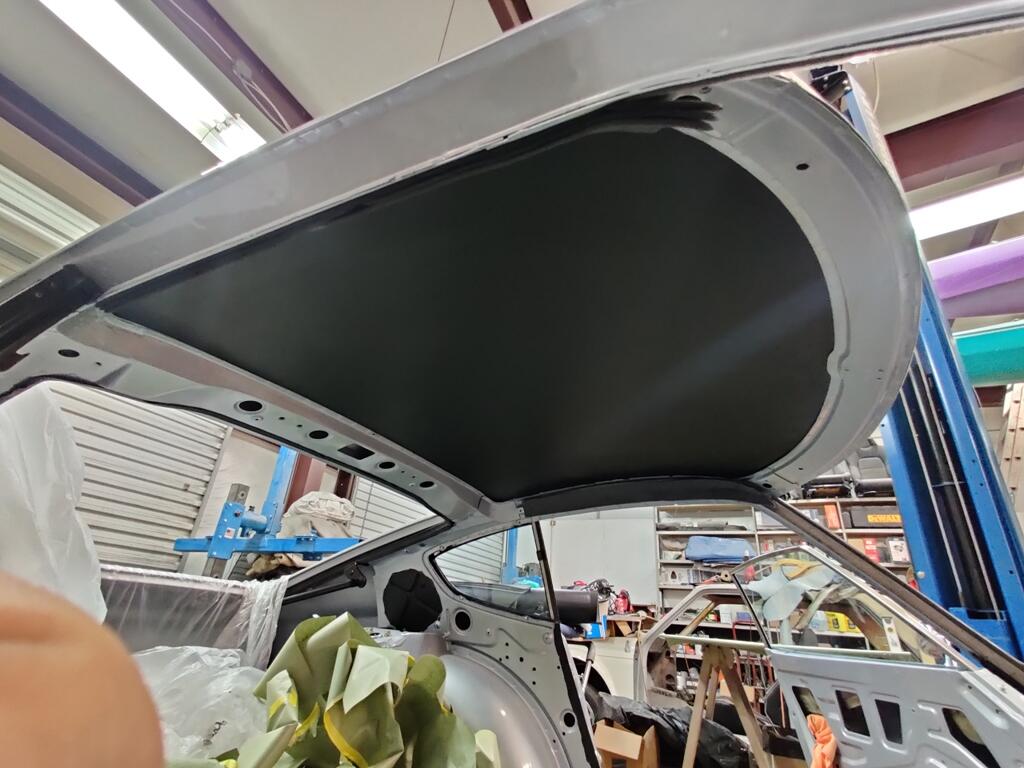
Thank you - very kind of you to say! Today, I picked back up with gluing interior pieces. Spraying glue is not something I have much experience with. So, I was nervous about installing the new headliner in the car. For example, I don't really know the right amount of glue to apply. Too little, and it might stick for a while, but fail later. Also, there is an amount of drying time that is important. Depending on the size of the piece being installed, you may have to wait a length of time, as the adhesive doesn't stick well when it is too wet. Or, if the piece is very large, you don't have to wait long at all, as it took some of that waiting time to apply the glue to the large surface area. There is a window of time where the glue transitions from wet... and a "tackiness" develops. After more time, the adhesive feels dry to the touch. And yet, if you put two pieces with seeming dry adhesive together, they can stick immediately... and not allow for pulling apart for "re-alignment". Over the past two days, I have found that waiting is necessary, but the pieces should be assembled when the glue is still at the "tacky" stage. At this stage, you can pull it apart and reposition a bit. If you wait until it is dry to the touch, then when you put the pieces together, they stick pretty strongly, and it is not going to go well if you try to reposition things. With all that weighing on my mind, I worked on cutting foam and vinyl pieces for the windshield header and side panels. I carefully examined the old foam and made new pieces that matched the thickness, width and length. Because some of the original pieces were only about 1/8th" thick, I bought that thickness of replacement foam. To match the thickness of the other original pieces, I stacked new strips of 1/8" thick foam, using just small amount of glue brushed down the center of the strips so they would stick together. From the old pieces, you can learn things, so you should keep them until your new pieces have been installed. For example, by looking at these indentations in the end of the old foam, I was able to eliminate any question about the correct location of the foam on the inside frame. I was also able to determine where there was overlap of original foam pieces. And that helped me locate the a-pillar piece of foam on the car in the same place as it was done by the factory. This foam compresses with very little pressure. While stacking 3 pieces high was a bit thicker than the original, it compresses easily, and will compress to the proper thickness when the vinyl is pulled and stretched over the foam. After getting the grey foam in place on all three sides, I masked off the frame area as described in the how to Restore you Datsun Z car book. Then, I took a moment to organize things so I could spray the inside of the roof of the car, and the back of the new headliner, and install the headliner in the car. When masking the rails, I made sure not any part of the rail surface was exposed to catching any adhesive. Even a tiny portion of the edge of the frame, if exposed, will subsequently collect some of the spray on adhesive. And it will become a problem when you go to position the adhesive covered back surface of the headliner in place. A touch of cement on the frame, if present, will touch the cement on the back of the headliner and "bite", causing difficulty with getting the headliner, up and over... and subsequently tucked behind the frame edge. Speaking of tucking behind the frame, I used a large plastic body filler spreader, which turned out to be a great tool for the job. There was a fair amount of force necessary to get the headliner to go from outside the frame to squished... and then, using the edge of the spreader... pushed inside the gap between the outer panel and the roof structure. The "extra" headliner material has to flatten out (behind the frame, hidden from view). Again, I was very happy when, like the gluing operation to adhere the vinyl to the foam to make the headliner, the installation of the headliner also went well. There were a couple of nerve racking moments, and 3/4 of the way through getting the edges tucked behind the frame, I was feeling some fatigue in my arms and soreness in my back from getting poked by various "not soft" parts of the transmission tunnel. From there, I started the next project: to install new vinyl onto the windshield header (front portion of the roof frame) and the side panels (side portions of the roof frame). I found it best to do things here different than Wick Humble's guidance. I was able to use a small brush and only apply adhesive to the underside of the back weld flange of the header. I let that dry a bit, and then positioned the header vinyl directly on that adhesive. I didn't use the welting at all, initially. The vinyl was simply hanging down from the back edge of the header, across the header's full width. Then, I aligned the white dot on the welting with the center of the header. I pushed the unglued portion of the header vinyl upwards and pushed the welting onto the back edge of the header, forcing the vinyl to tuck between the new headliner and the frame. The glued part of the header vinyl did not move as I did this. Only the non-glued part squeezed between the new head and the frame. At this point, the header vinyl is held captive by the welting, and it is ready to be pulled forward, and out through the windshield opening. It will need to be pulled with a good amount of force so as to compress the foam that is on the header, and create a tight, wrinkle free finished appearance across the entire header panel. And that has got me thinking... I don't know how in the world they did that at the factory - keep a lot of tension on the vinyl covering the header panel. The way the windshield goes in, the windshield gasket tends to push the vinyl on the header backwards. If the glue holding the front of the header vinyl were to not hold firm, the vinyl would be pushed back somewhat, allowing the header vinyl to relax... and be loose. If that happens, the finish look is not going to be nice, and who wants to pull a windshield BACK OUT, just to fix a loosely fitting header vinyl? I am not sure how I will proceed. But, I am thinking about buying a whole bunch of these, which I have seen other people use on other car restorations. I think I will need to apply the glue, and wait for it to dry... more than I have been, so that it will have the most strength possible. And then, I will pull the vinyl a good bit to the get material tight, and wrap it around the windshield weld flange, and clamp it in place very tightly to keep it from slipping back and causing a loose fit. And the glue will need to dry for at least 24 hours before I attempt to install the windshield. So, that is what I am thinking. Anyone else have luck using a particular technique?