inline6
 Subscriber
-
Joined
-
Last visited
Everything posted by inline6
-
 "This 240Z is now offered on dealer consignment in Oregon". Some sellers hire BAT specialists. I believe 911R is just a specialist who does the photography and perhaps handles working with the person from BAT assigned to the car.
 -
So... if the market is soft, it is a very interesting time for the "Franklin Mint" car to come back to BAT: https://bringatrailer.com/listing/1970-datsun-240z-128/
-
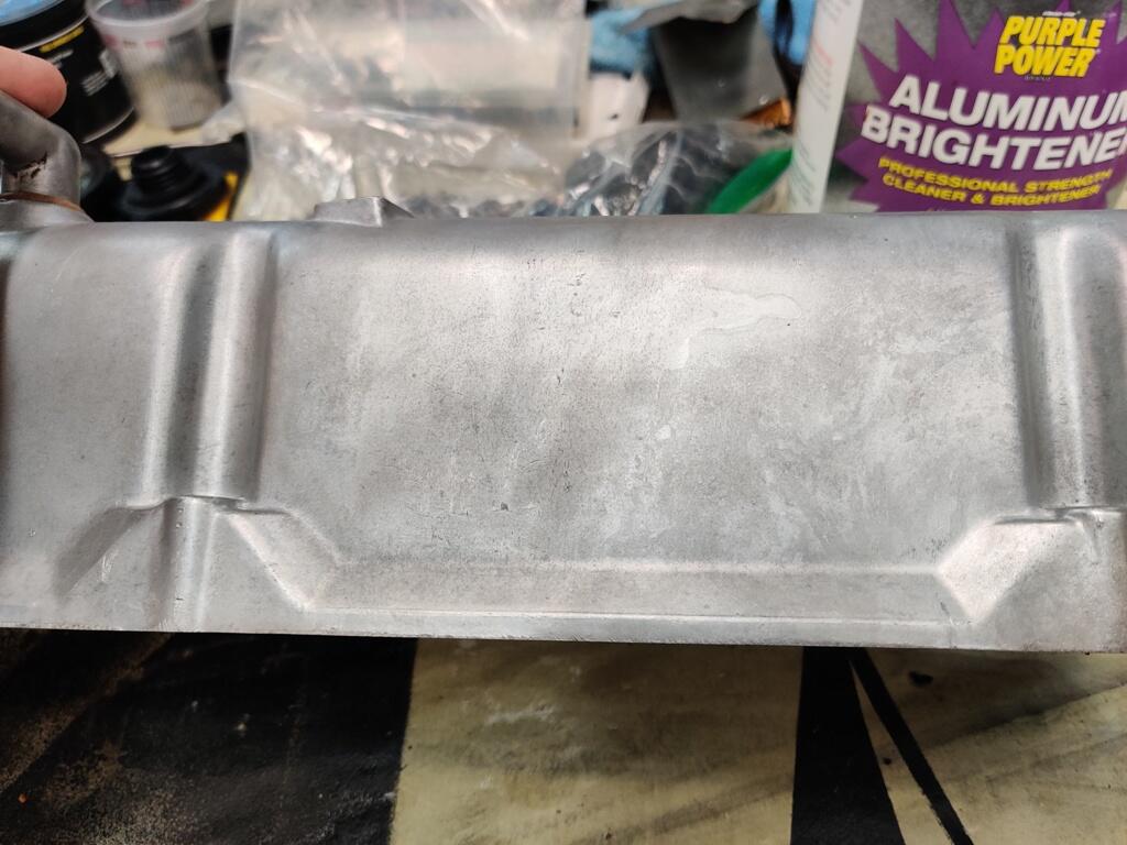
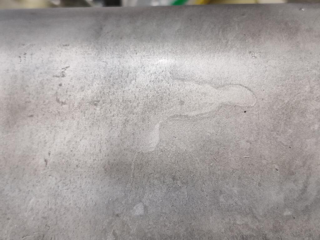
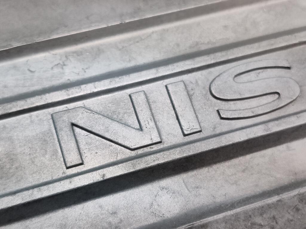
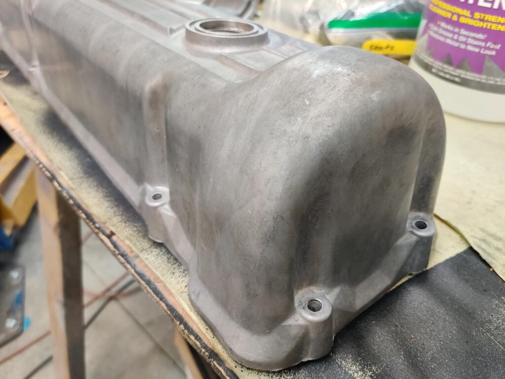
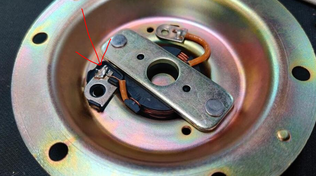
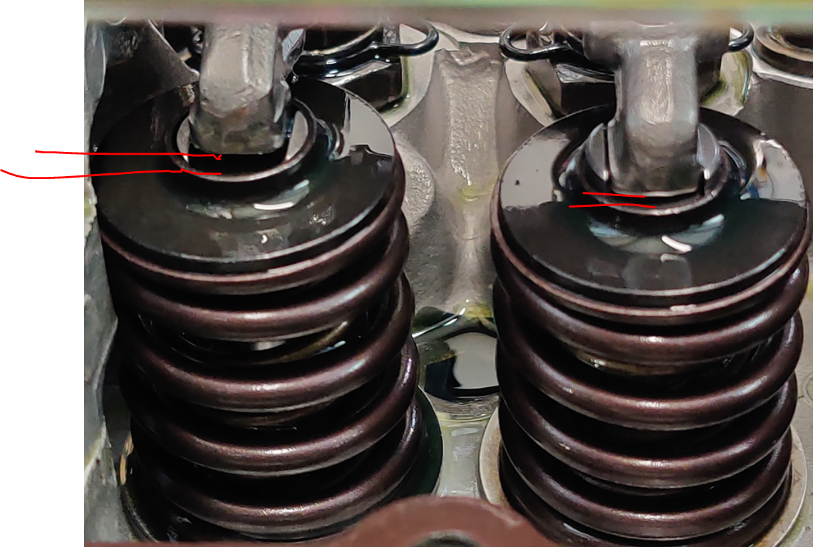
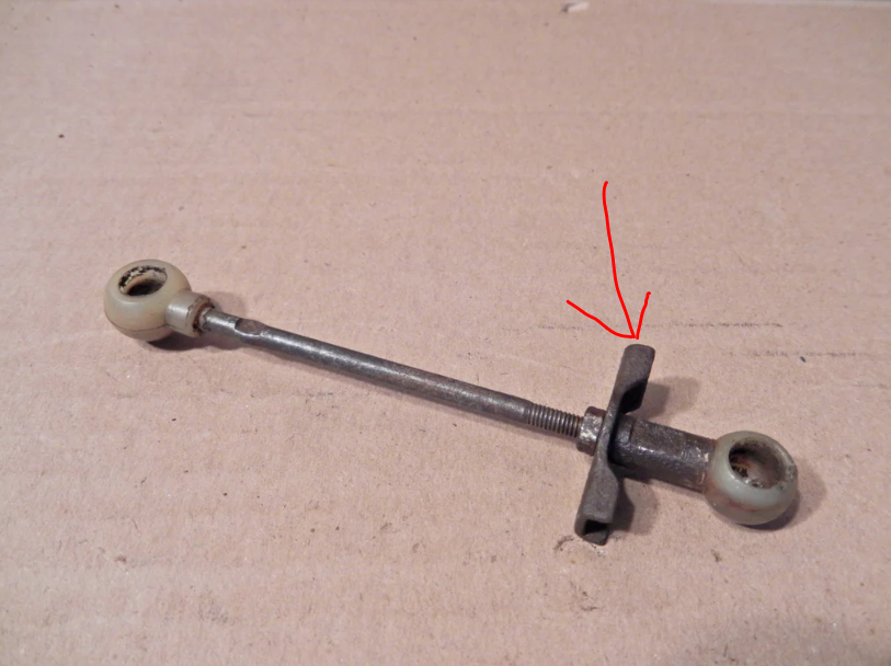
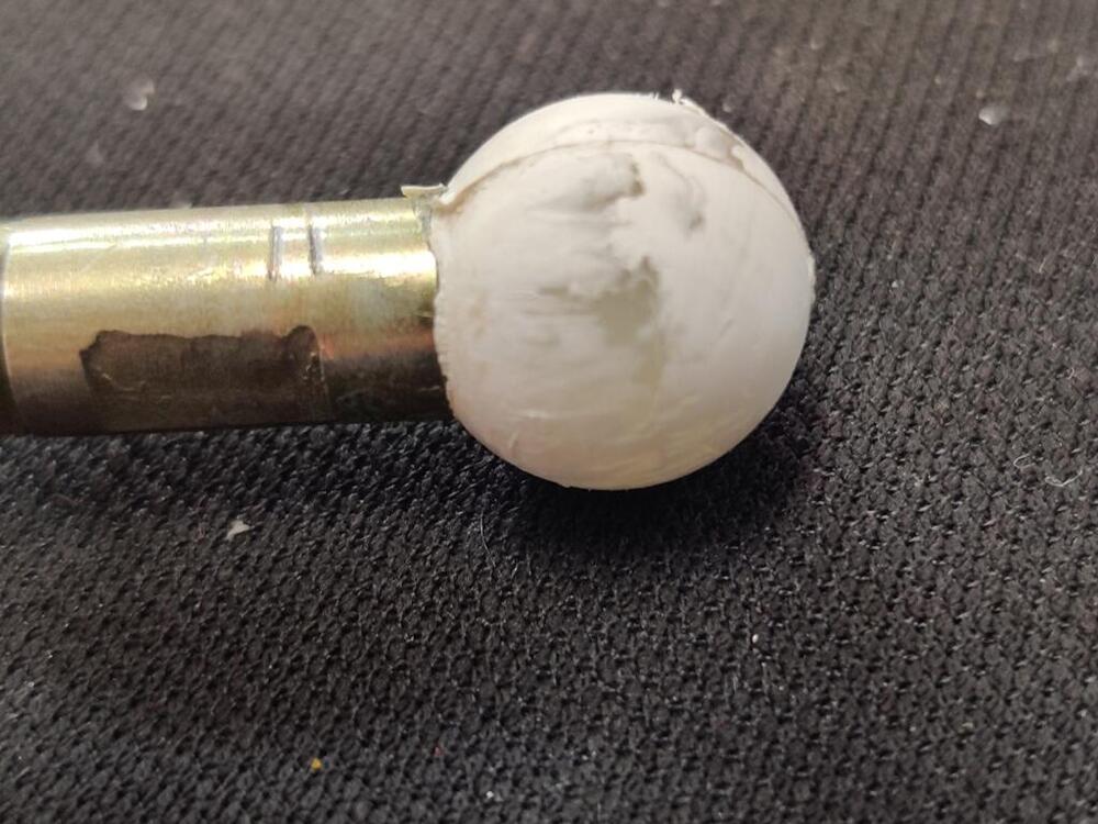
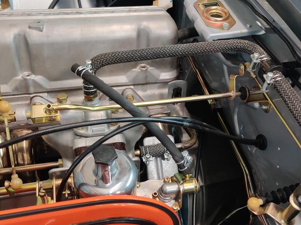
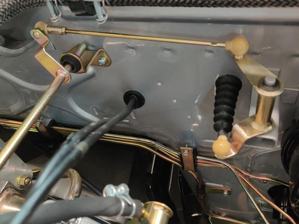
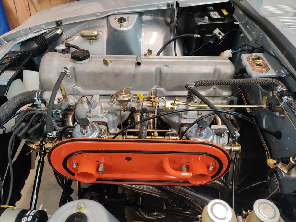
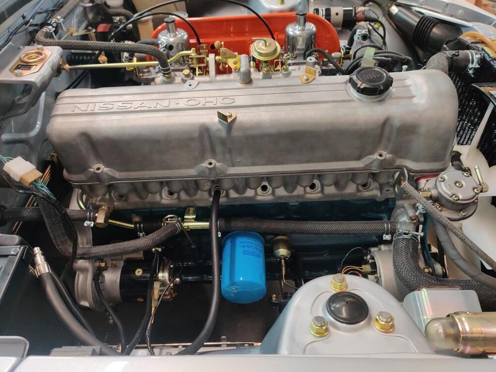
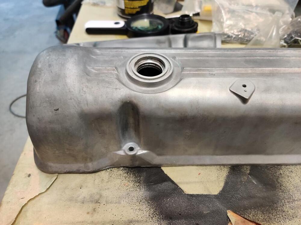
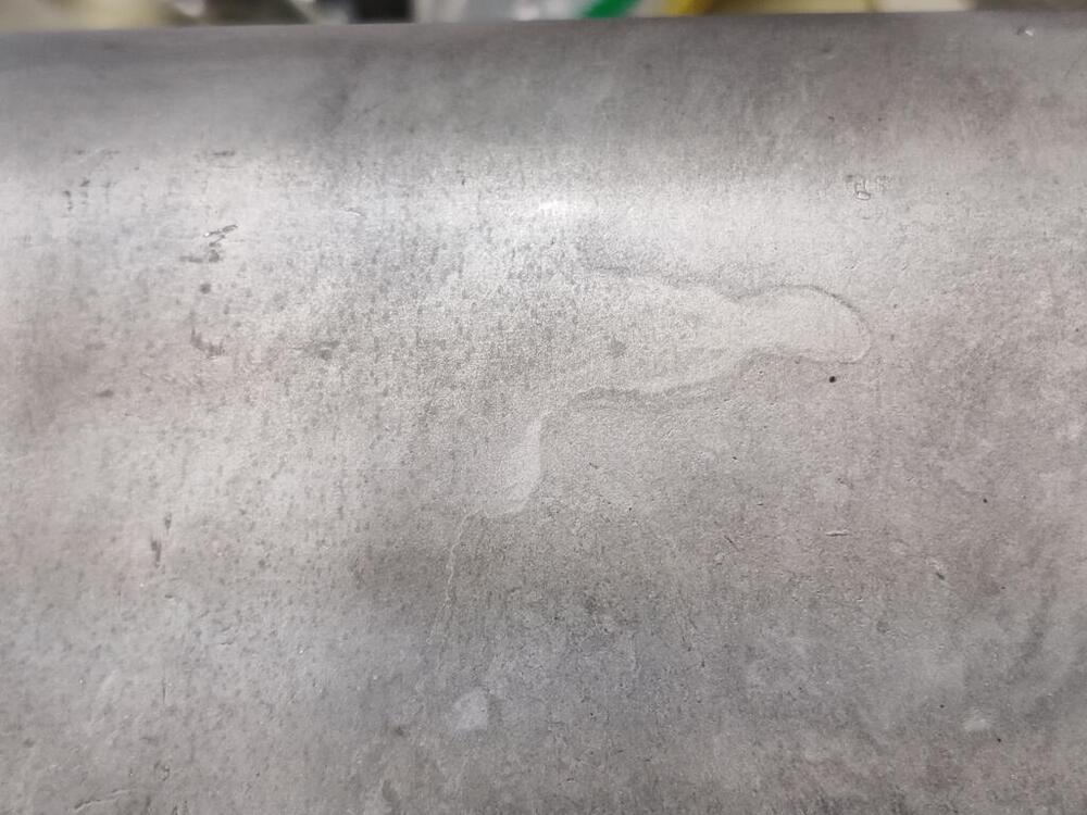
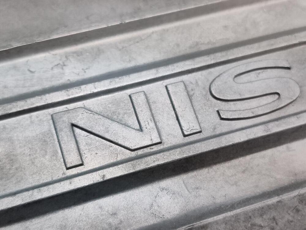
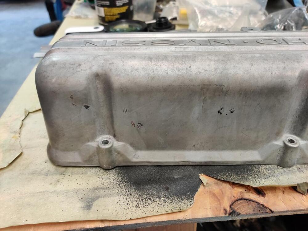
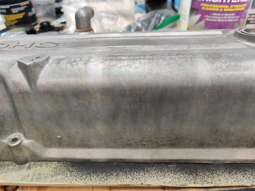
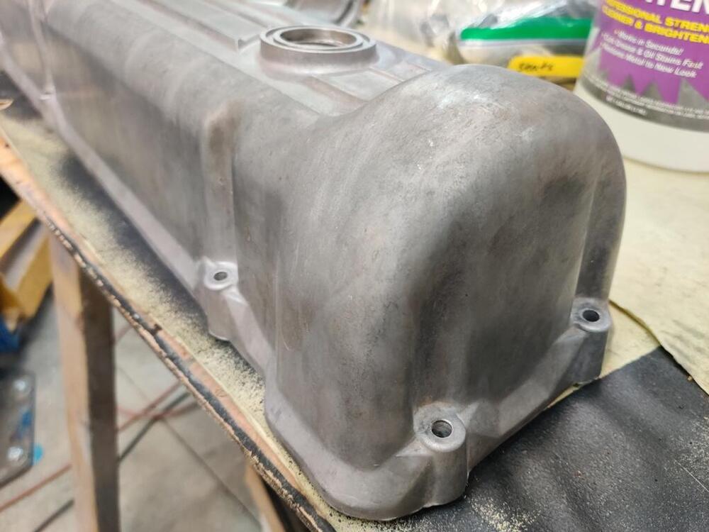
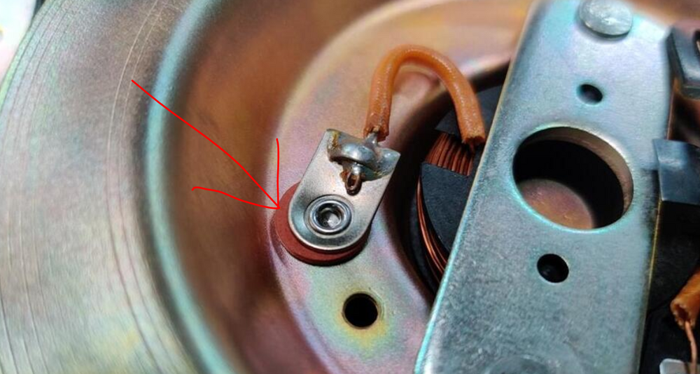
I attempted to remove the valve spring retainers from my exhaust valves this weekend with the homemade valve spring compressor tool I have use successfully before. However, this time, it didn't work as well as I recall it did last time. After futzing with it for a couple of hours and only getting one retainer off, I gave up and ordered one from Zcardepot.com. My homemade one interferes with the came towers and extracting the collets out is a real pain. Hopefully the new one will be a lot easier to use. In the meantime, I am working on what there is left. One of those things was installing and adjusting the throttle linkage arms. While I am familiar with this part (see red arrow), I never knew what its purpose was - do you know? Well, I may have figured it out. I think it is a linkage "stop". As I was assembling the linkage, it seemed logical to me that the little wings on this part may have been intended to contact the back of the rubber bellows that attached to the firewall. As I worked to set the lengths of the rod (this short one and a longer one have one threaded ball socket end) the location of this piece fell naturally to a position that eliminated all of the "slop" in the linkage after the throttle plates in the carburetors had just contacted their screw stops. In other words, you can then set the depth of this "winged" piece to contact the back surface of the bellows just at the point where the throttle plates in the carburetors have closed. Doing this, you will prevent introducing slop in the linkage which occurs after the throttle plates are shut but you continue to release the gas pedal as far as the pedal return spring will pull it from the floor. After setting the winged piece, I confirmed that even the slightest movement at the pedal caused carburetor shaft (and thus, throttle plate) movement. When releasing the gas pedal I now have a muted "thud" as this piece hits the back of the rubber bellows... and allows no more movement in the linkage beyond the throttle plates in the carburetors' seating. Kind of cool! It will be interesting to see how that all feels when driving the car. While I was doing all this, I ensured that I got full throttle opening at (both) carburetors by pressing only on the gas pedal inside the car. I am never all that surprised when I check and find that pressing the pedal to the floor does not fully open the throttle at the engine! The plastic ball sockets on the linkage turned white during the plating process. To address, I used a propane torch and very carefully heated them. The heat causes some type of reaction which restores the color of the ball socket. But, you have to get it hot enough that melting starts to occur. After heating, I went over them with some fine grits of sand paper to restore areas that has melted a tad. White socket... and my throttle linkage stopper in action (though I think I need to flip it around 180 degrees): Throttle linkage detail: I have read about getting dinged at Zcon for valve covers which have been glass bead blasted. I also know that there is quite a bit of variance in finish with glass bead blasting. You can use different media, different pressures, and even do vapor blasting which uses media along with water. For my valve cover, I tried cleaning it really well with #0000 steel wool and degreaser. And then I tried some Aluminum Brightener. After those efforts, I still had darkish areas that looked like stains on my valve cover: So, I started experimenting with glass beads set at very low pressure. The glass beads I was using have seen may work cycles and I was using only 20 psi. However, I was getting pretty good results. In this first pic for example, I concentrated efforts on the area at the top of the valve cover between the oil cap hole and the casting bump (for the spark plug wire holder). In the second picture I was concentrating in the area between the two bolts. In the third picture you can see the area of transition (darker, not blasted area on the right). In this first picture below, I had hit the N and and the I in Nissan and some of the area above and below the N. The downside is that it takes a lot of time at 20 psi. But, it did make a big difference in lightening the valve cover. I got a little more aggressive in a few areas with 25 psi, but I think that started to look unnatural. Anyway, I was pleased with the overall result. A note, if you do this, you have to seal the vapor compartment in the valve cover, or remove that plate inside the valve cover like I did so that you don't leave glass beads in there.

-
I have seen some cars with original backs in very good condition, but the bottoms not. And I have seen some where the bottoms have been replaced but not the backs, like this one on Bringatrailer a while back. https://bringatrailer.com/listing/1970-datsun-240z-101/ For the right person, they will be valuable. But, quality aftermarket ones from Distinctive Industries exist also for about $600 (in black). If they are the early type (can you take a pic of them outside the bag?) I'd put their value around $600 - figuring if I had good original backs (rare), I'd be will to spend that much to try to keep the seats original.
-
-
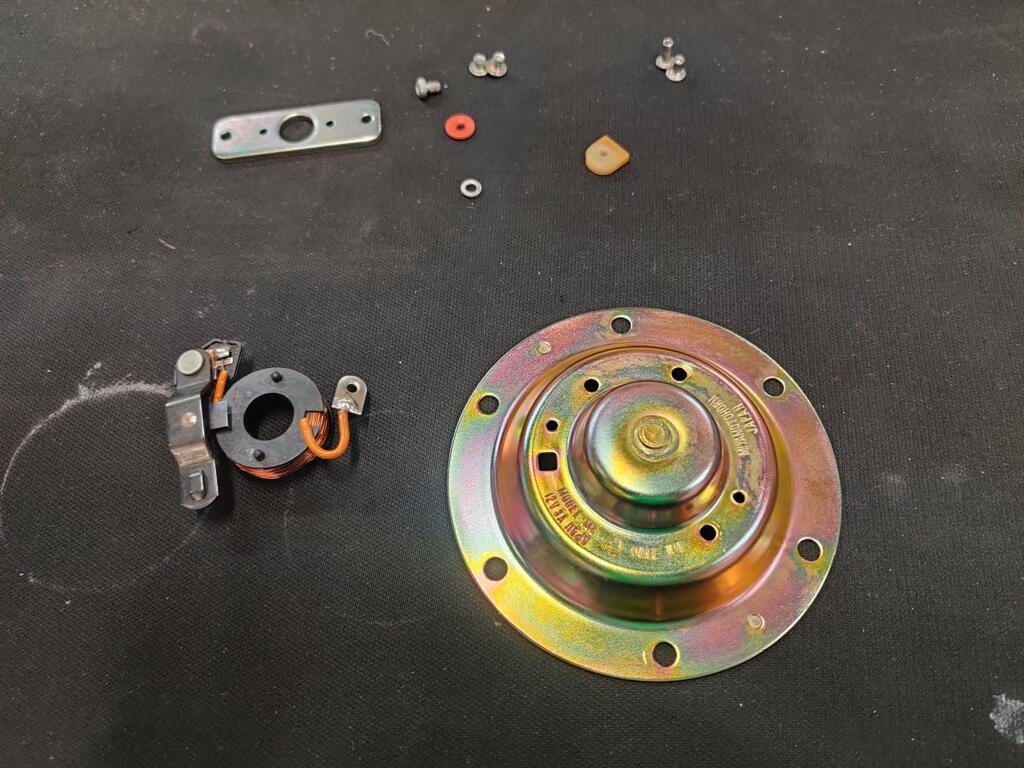
3 mm. I have some suitable items to take place of the red washer in my cart, but have to buy way more than I need. And, I would like that black plastic piece too.
-
I have been saving a lot of money on shipping since I started using Stamps.com. I had no idea that using them, I could get much better than over the counter shipping rates. All I did was create an account, and fund it with like $50. I put in the address, dimensions and weight of the package (box or padded envelop), print out the label and drop off at a UPS store. I bet shipping a horn would be less than $8. Anyway, I managed to lose one of these red washers: And, I'd like another of these black plastic parts. However, both are only accessible after drilling out the rivets and they are easily damaged if you are not careful. I'd rather pay for the shipping and do that part myself.

-
Anyone have a 240z horn they'd be willing to part with for cheap? I need one to cannibalize from.
-
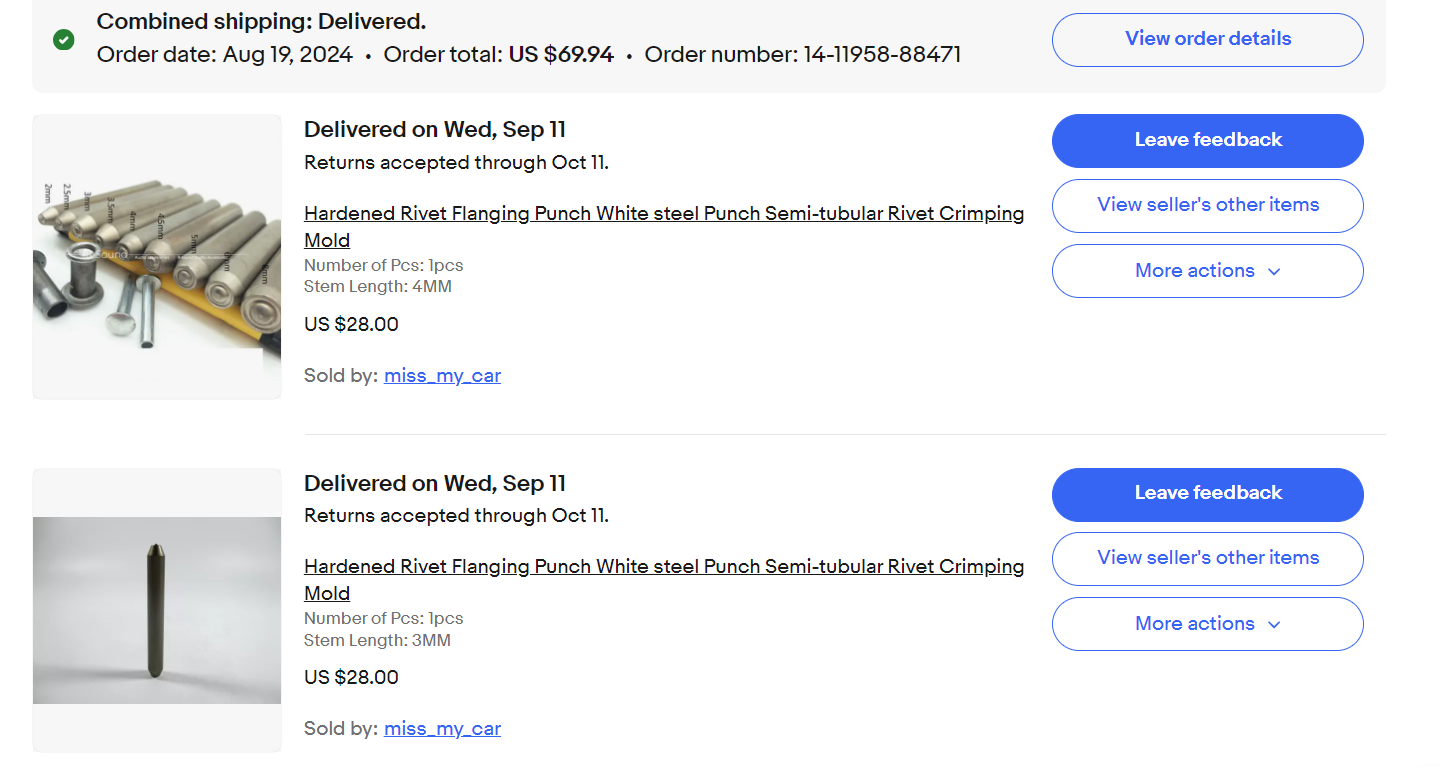
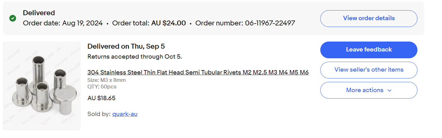
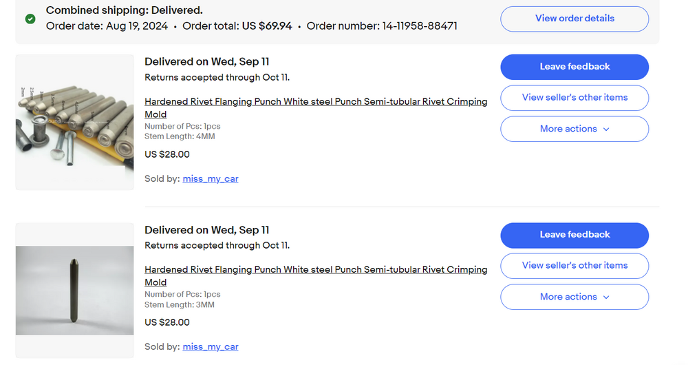
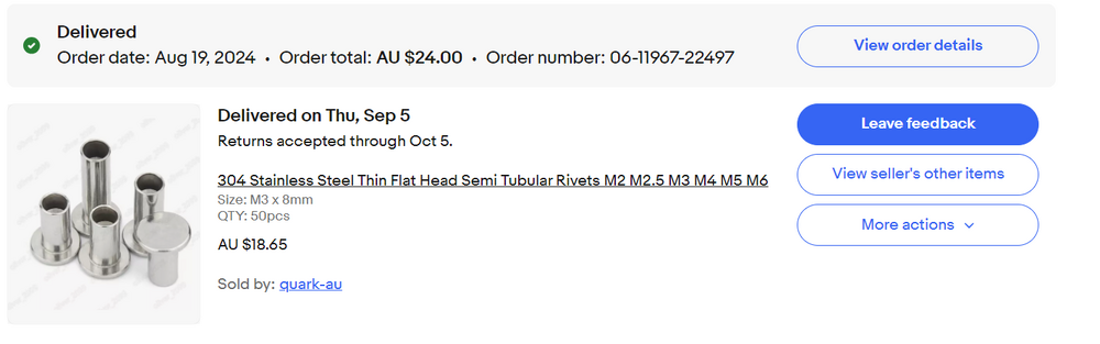
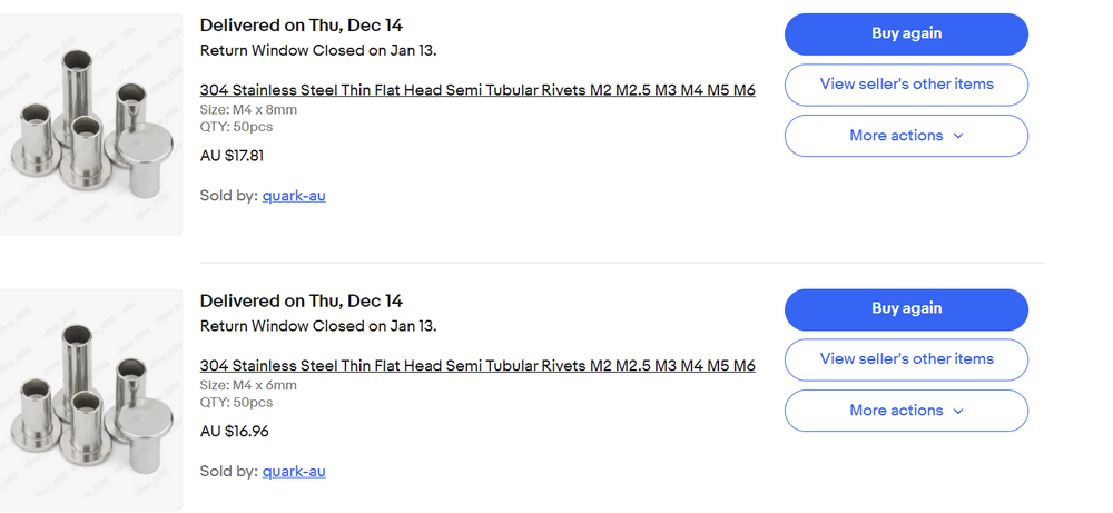
Tools: Rivets: note diameter and length. I can send you some rivets as I have many to spare.
-
Date code on that block indicates manufacture date is May 12, 1972. Stock head at that time would be an E88. Some parts may be of value to the stock restoration crowd. Air galley pipe, air pump... the fuel pump if a "Nikki". Block may be of interest to vintage racers. E31 heads still have value as people restoring the early VIN cars need those.
-
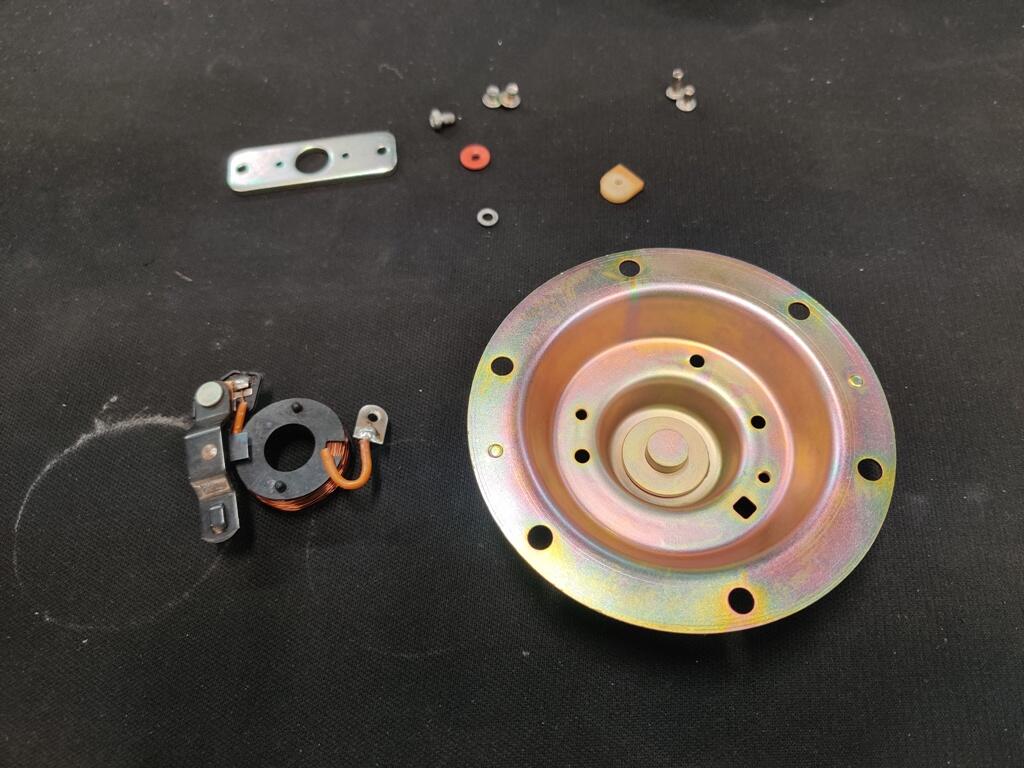
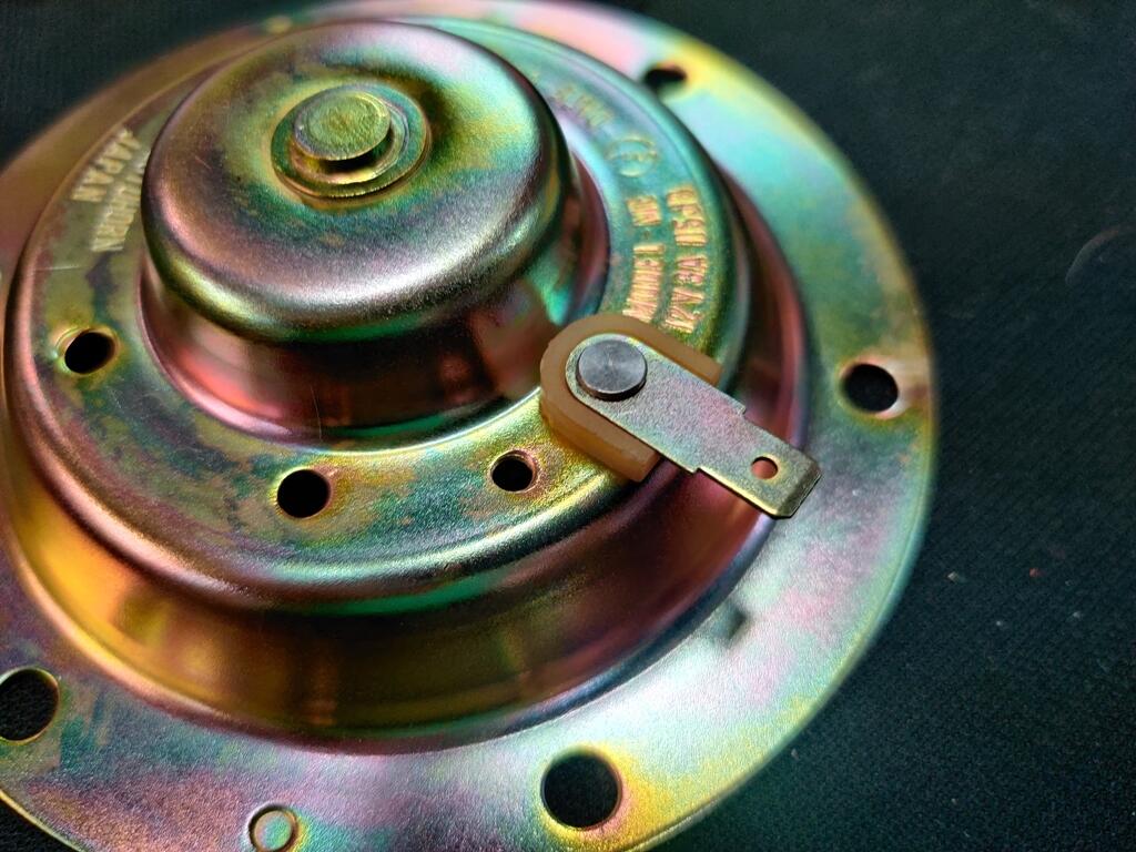
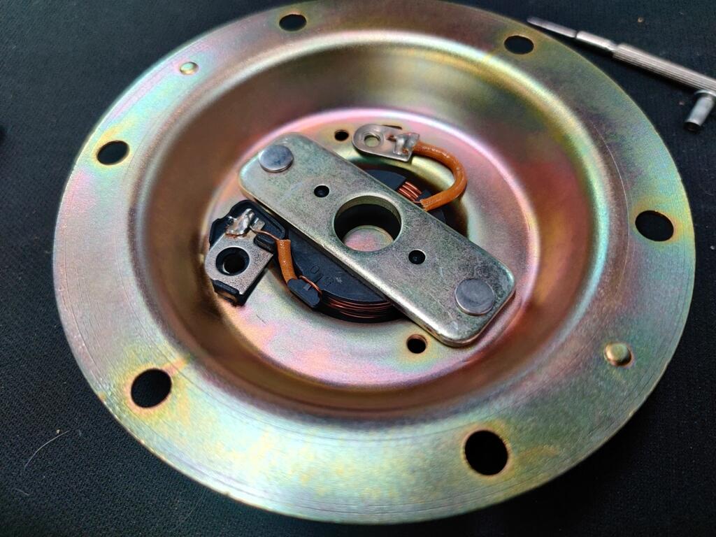
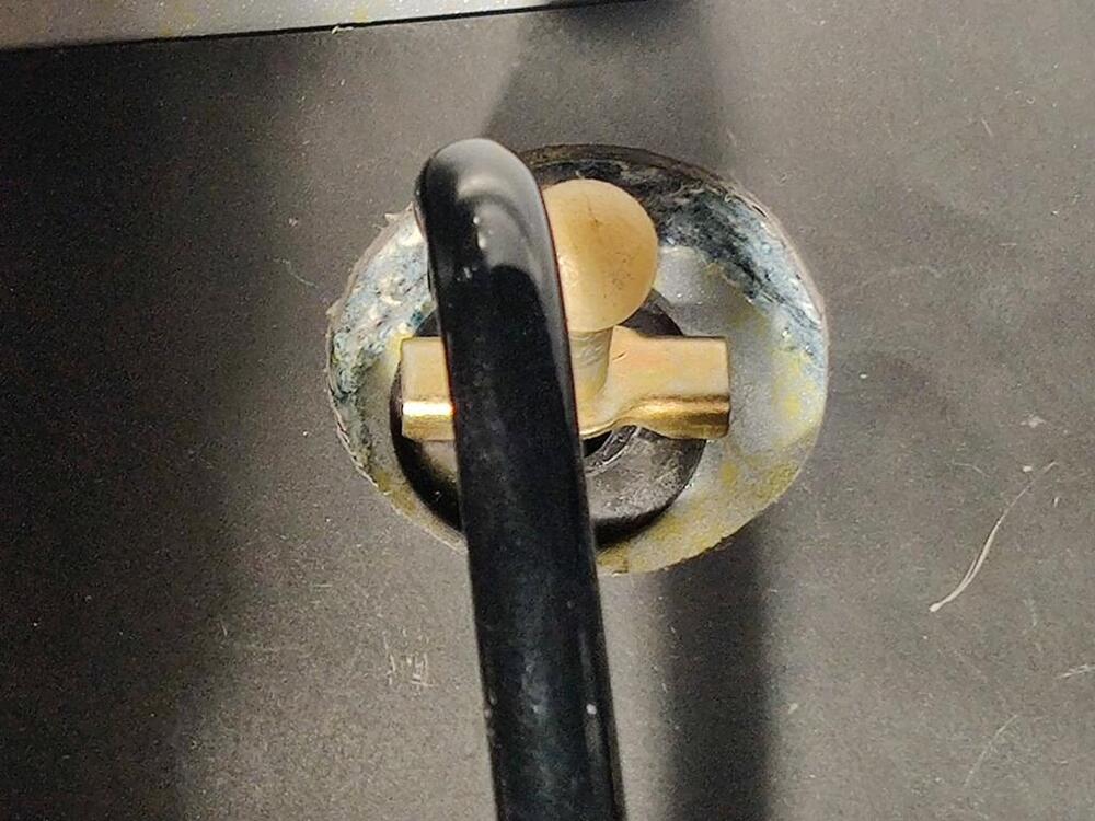
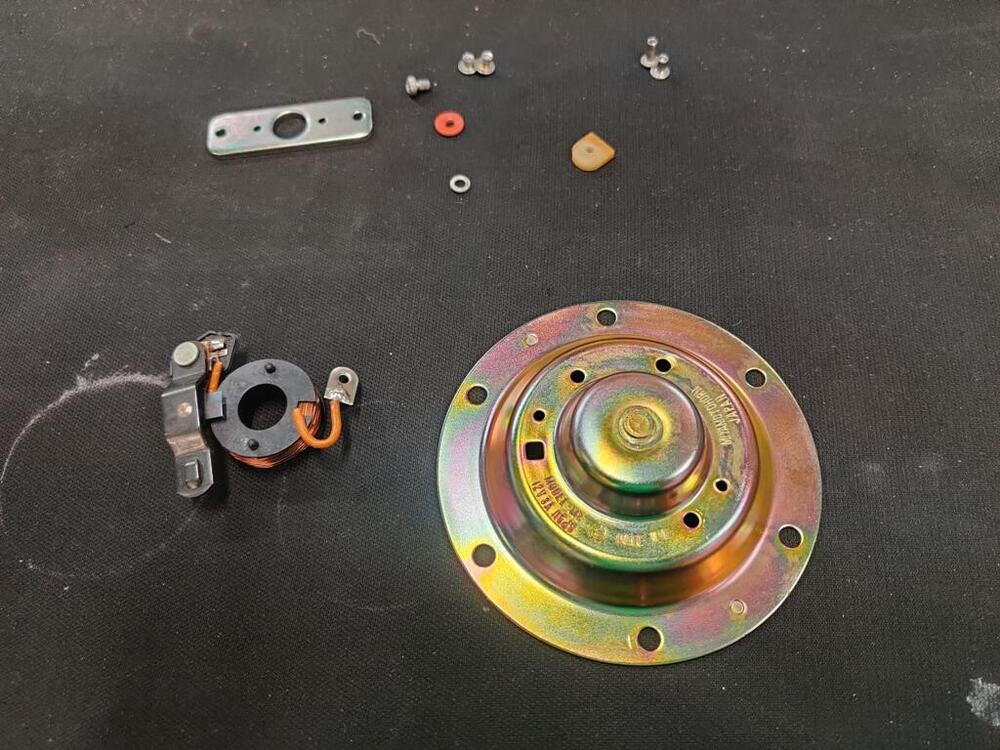
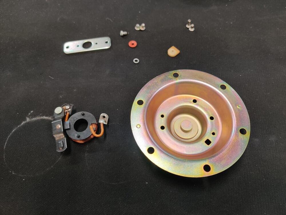
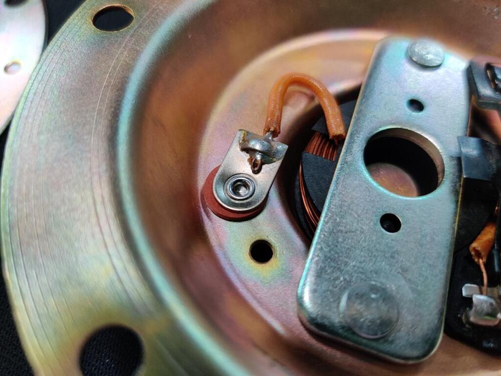
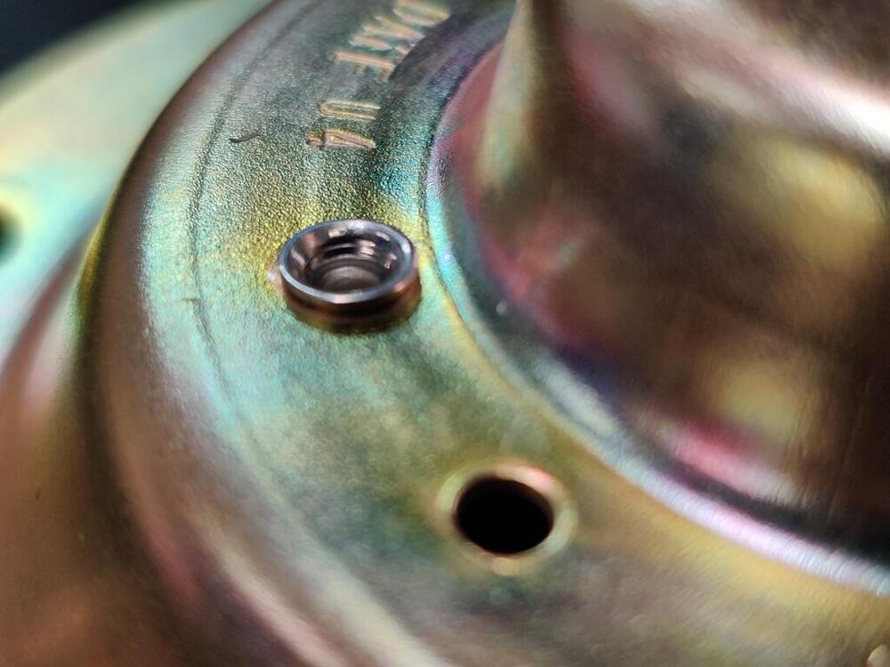
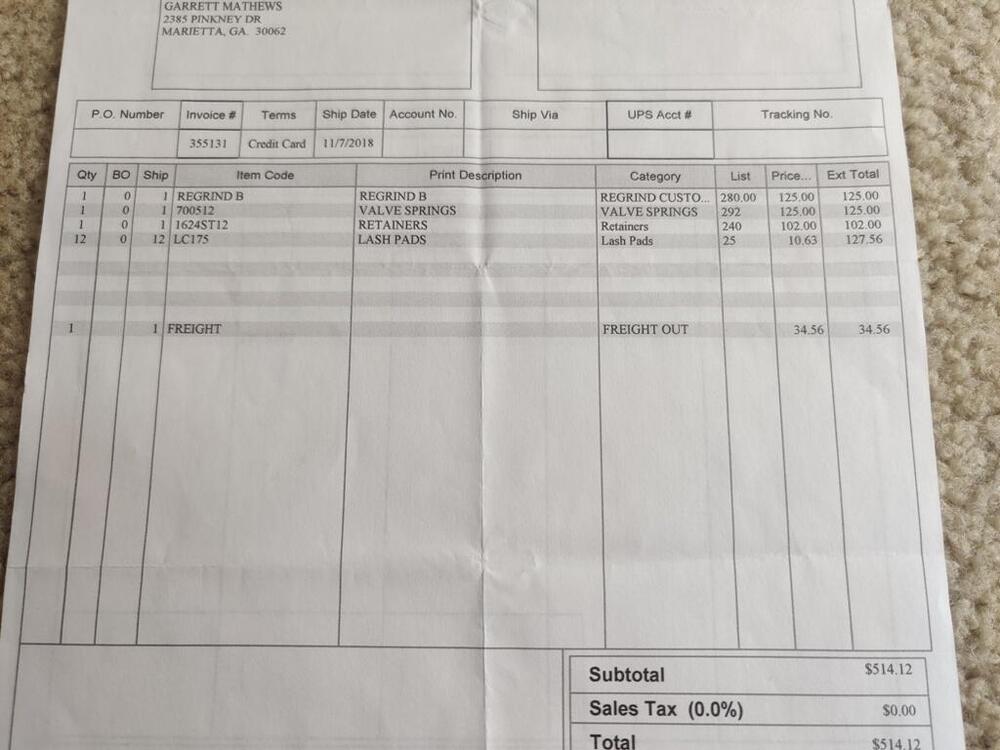
Recently, I sent off a small box of hardware for plating. Unknown to me, the place I sent the parts to had gone out of business, and my box got hung up in the UPS/USPS system for quite a while. But, I was successful in getting the box of parts back finally, after many weeks. I found another plater, and sent the parts off again. He got them done literally over a weekend and got them back to me already. For the horns, the first plater I sent them to wouldn't do them. So, this time, I drilled out the rivets holding the electrical parts to the back plate and sent the back plates off for re-plating. I had to order "semi-tubular" rivets and "rivet curling punches" to set the new rivets. Today I experimented a bit with those. The rivets for the "bridge bar" need a bit more work, I think: The rivet for the spade connector looks perfect: Didn't have much time to work on them tonight, but should be able finish them up this weekend.


-
I plan to use zip ties to around the stems to hold them up. I will rotate the engine to top dead center for each cylinder and use a leak down tester to input the compressed air. That will allow me to remove the spring retainer. Then I will put zip ties around the valve stem at the valve seal. This should keep the valve from dropping while I rotate the engine to the next one. I will need to do that for all six exhaust valves.
-
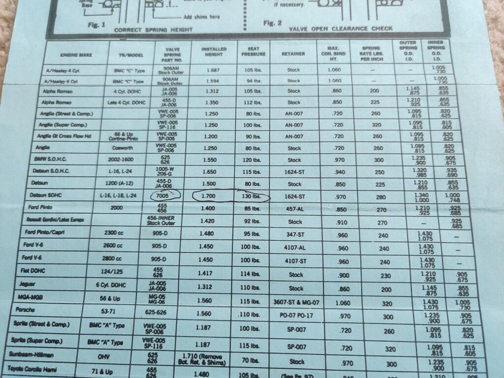
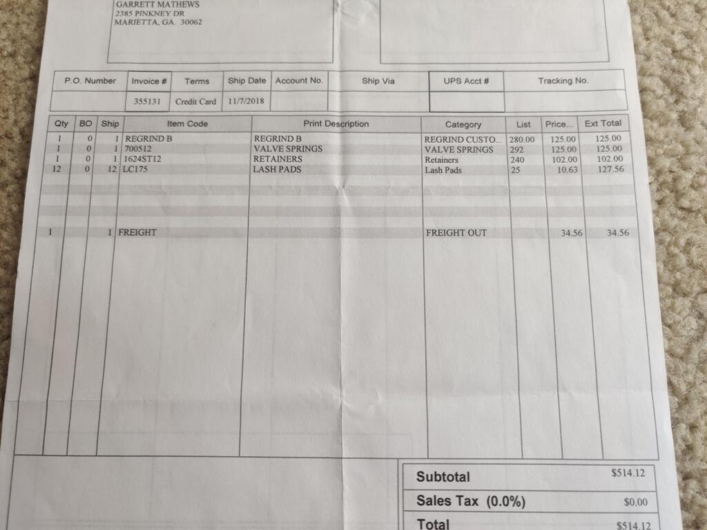
While it is true that the tip of the valve is going to be in the same location... and the lash pad will sit on top of that in the same location, the location of the upper spring perch is different between the stock and the Isky retainers. Therefore, just swapping out the retainer to a stock one is going to to change the location of the upper spring perch and the installed pressure of the springs. It may be possible to remove or add shims. I will have to investigate more closely. Here is a link and brief description of the retainers I bought. Chrome moly valve spring retainer set "Made in the USA by Isky cams. These will fit Datsun L series engines found in the 240Z, 260Z and 280Z. High quality parts made for racing or street use. Includes 12 retainers. These retainers will alter the installed height, for use with Isky high pressure springs PT# 800-1374."
-
I do not know offhand if the Isky retainers and the stock retainers are the same on the underside. They might be. I think that swapping to the stock retainers will alter the installed heights because the keepers lock in a different location relative to the spring seats. I will explore the possibility of using them this weekend when I pull off the Isky retainers.
-
Ok, it seems the exhaust valves have been "sunk" deeper than is "typically done". And, it is likely I now have a situation where installing the .175" lash pads which were recommended by Isky is not going to work like it would as designed/intended. So, what I am very likely about to do here (machine the retainers) is not "normal". I get it: going far astray from what is usual may not be wise. The Isky retainers can be used with a broad range of cam regrinds, but the one I am using in this engine is very mild when considering the spectrum of available options. Modifying the retainers to use these thinner lash pads in this instance doesn't seem all that radical to me.
-
"If the engine machinist picked the lash pads and declared the wipe pattern "correct", then he must have overlooked a real problem!" - I think that is accurate. I am willing to forgive this mistake. I've got incredible amounts of value from talking with him over the years, and he has done a lot of great work also. I think I consider myself fortunate that no significant damage was done, and we'll get it sorted out pretty quickly.
-
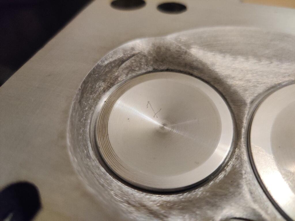
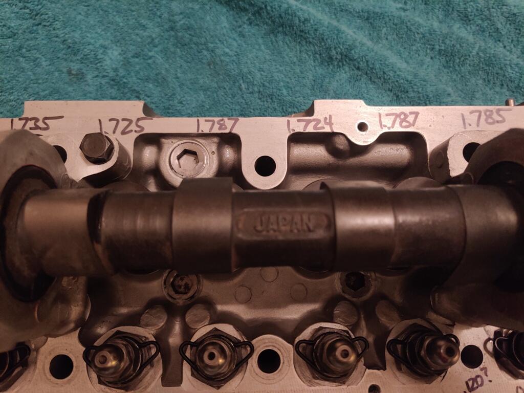
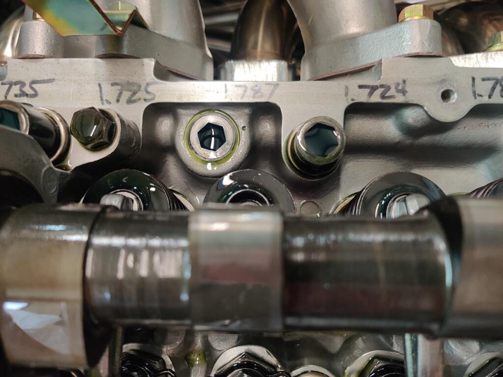
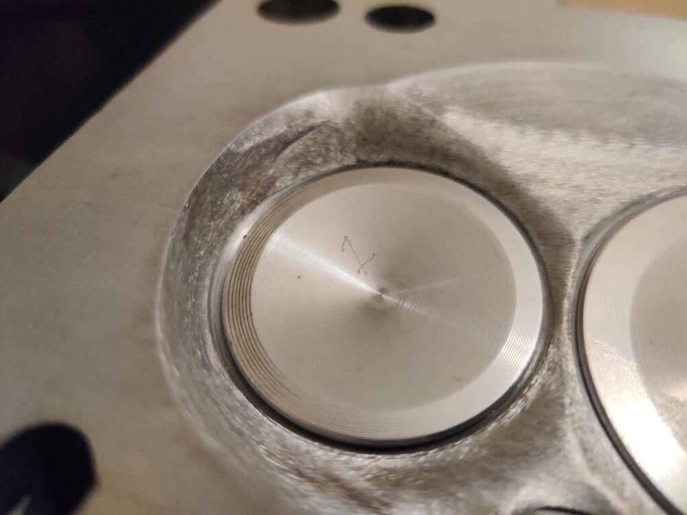
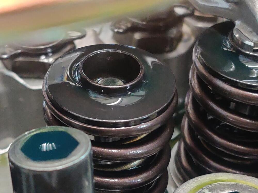
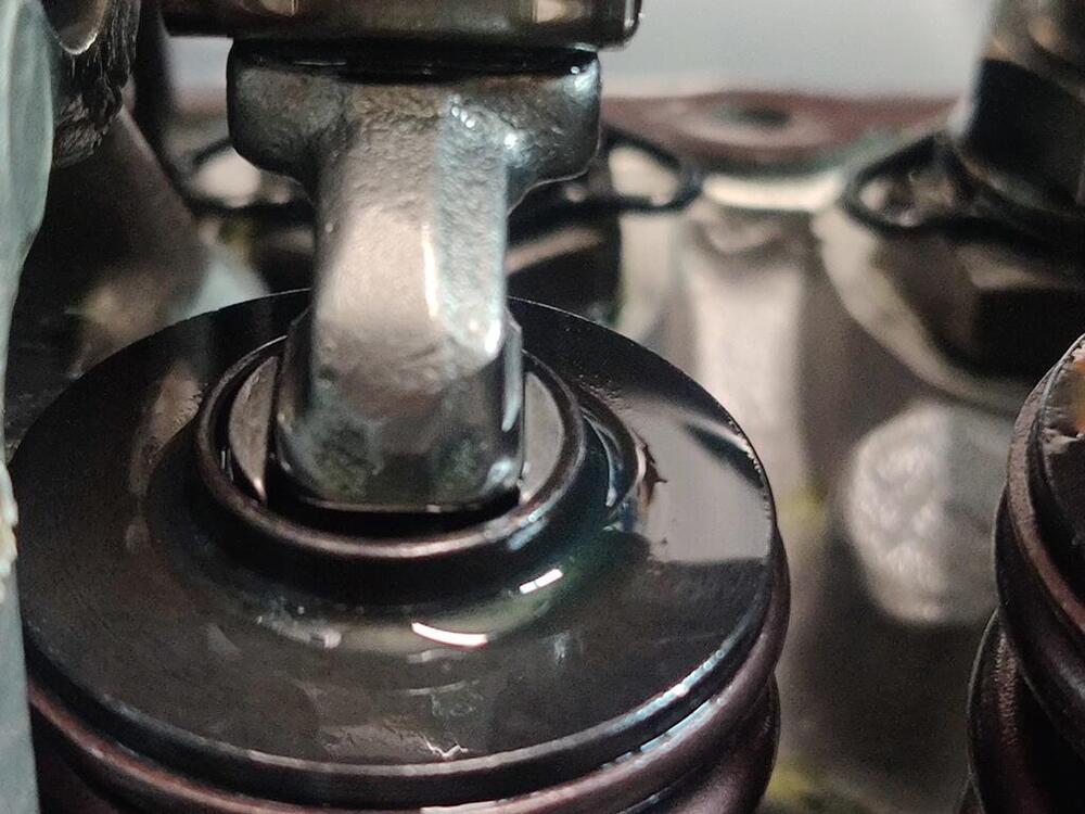
I will see if he will provide some info. I believe the main issue was the transition from the combustion chamber roof into the exhaust valve and that putting the exhaust valve deeper was done to improve flow out of the chamber. Here is a picture of the number 1 exhaust: And some of the installed heights. The 1.78 ish numbers are exhausts. The plan to fix is changing to removing the tall shoulder on 6 of the Isky retainers. My engine builder passed this along to me: "Your exhaust valve tip height is .050-.060 taller than the intake tip heights. This is reflected in the taller preliminary installed heights on the exhausts. It took lash pads that were .055-.060 thinner on the exhausts to get the cam sweep pattern centered, to match the intakes with the .175 pads. If you try to use the .175 pads on the exhausts, it may remedy the interference with the retainers but I believe it will screw up the sweep pattern. With use of a .118" lash pad, that shoulder protruding up on the exhaust retainers is only getting in the way, and not offering the support you would need with a tall pad."

-
While talking with my engine builder last night, we discussed that he purposely sank the valves into the head to address problems with the combustion chamber's archaic design. The location of the top of the exhaust valve stem is the issue I am dealing with. If the .175" lash caps are too thick for me to use (I will put them in and check wipe patterns), then I will go with his suggestion to remove the valve spring retainers from the exhaust valves, and send them off to him to have the ridges on the tops of them turned down to work with the thinner shims.
-
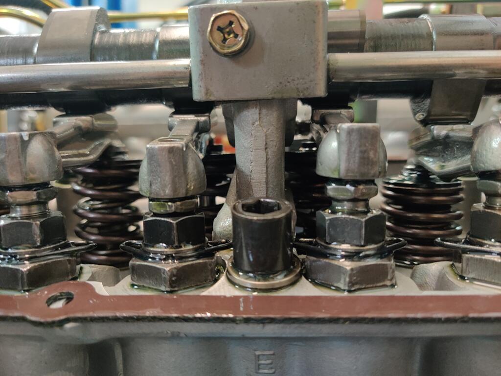
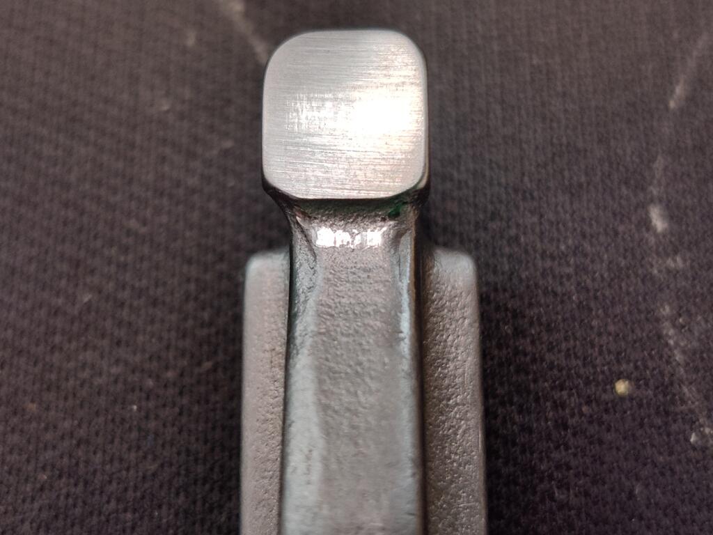
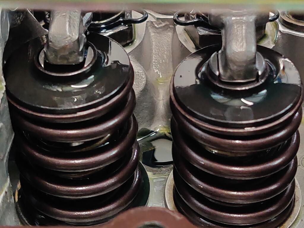
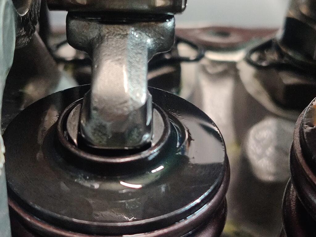
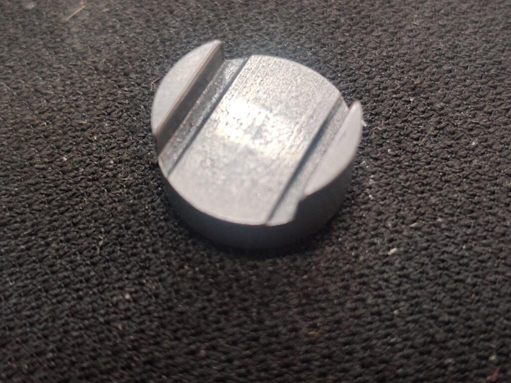
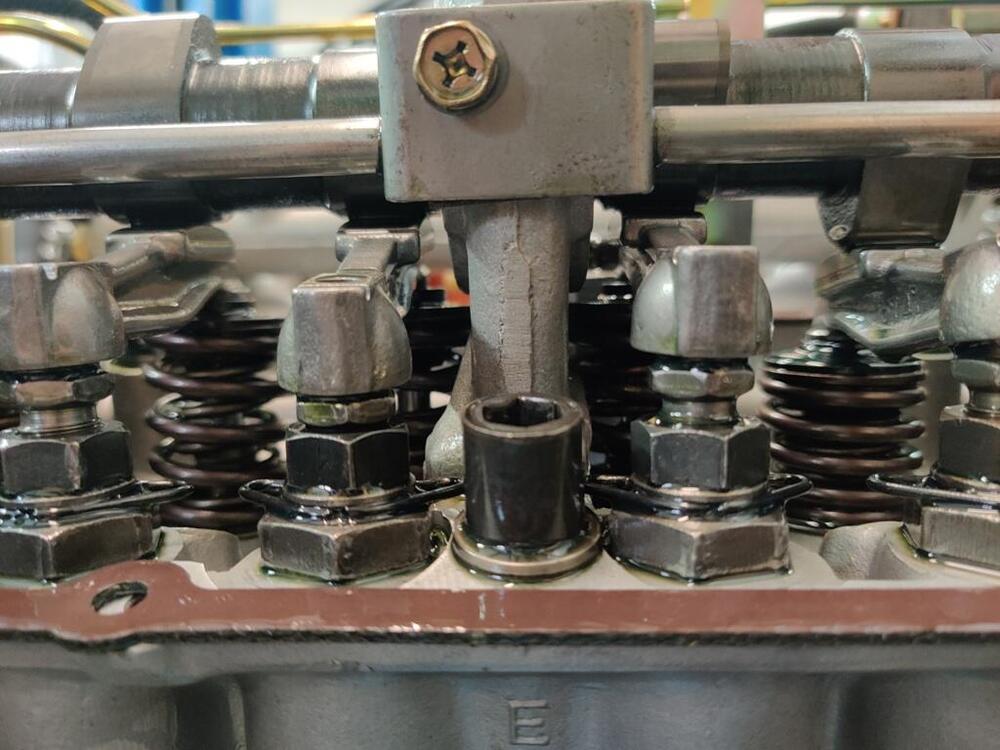
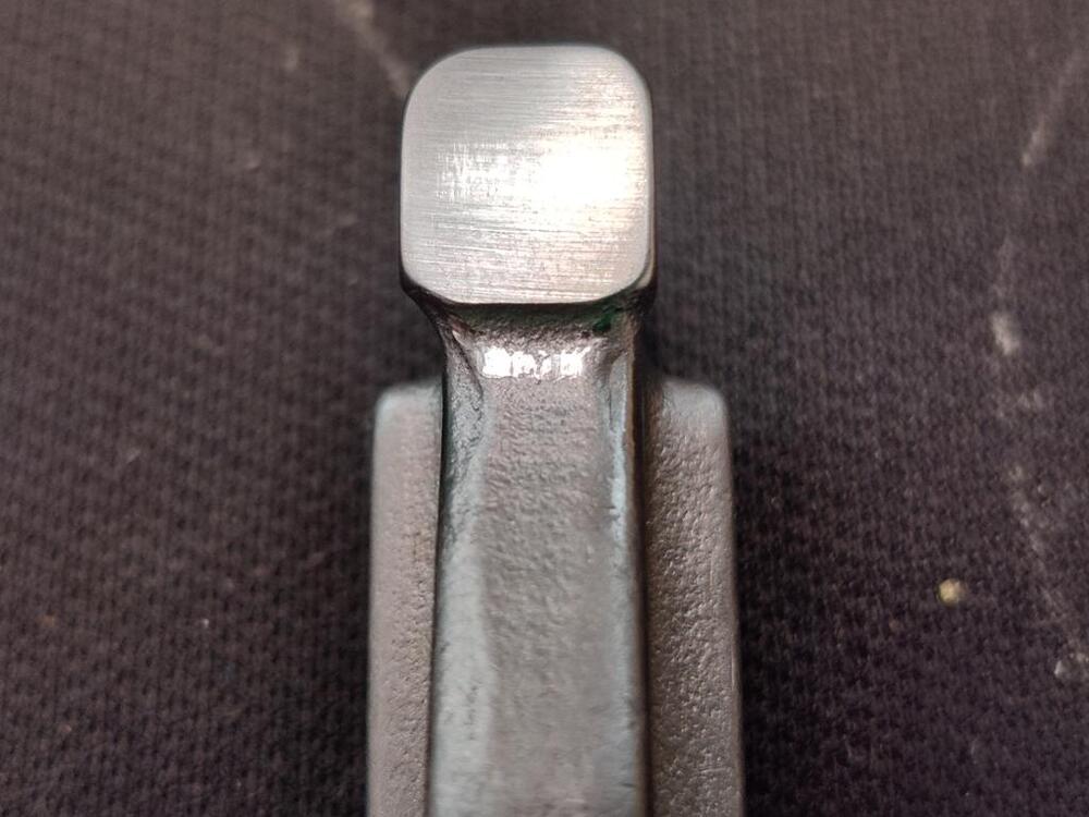
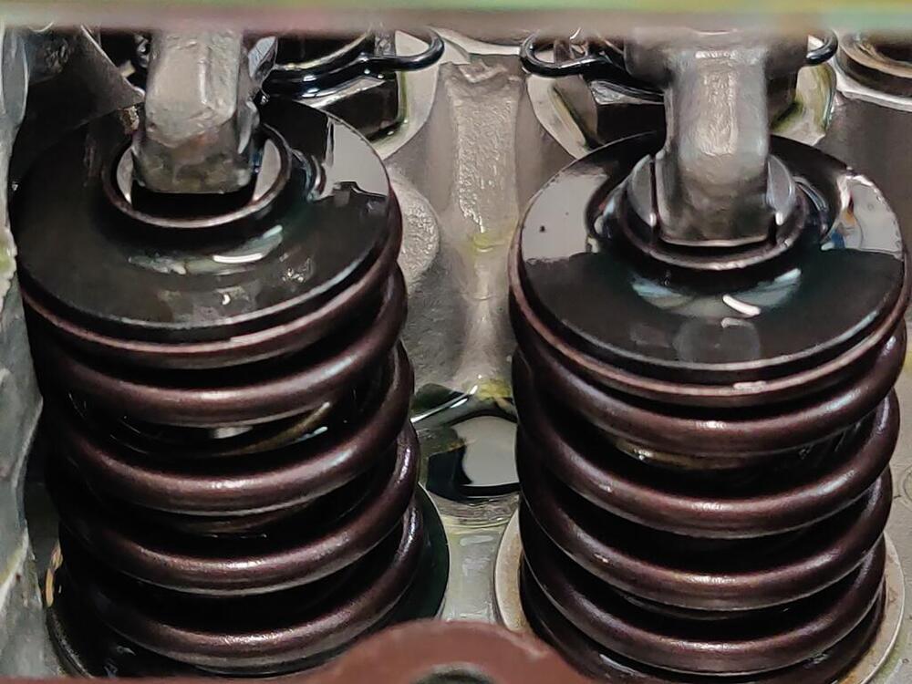
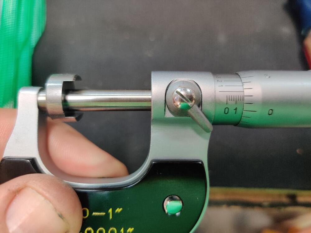
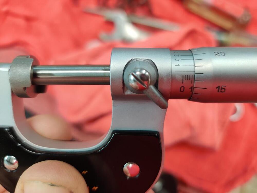
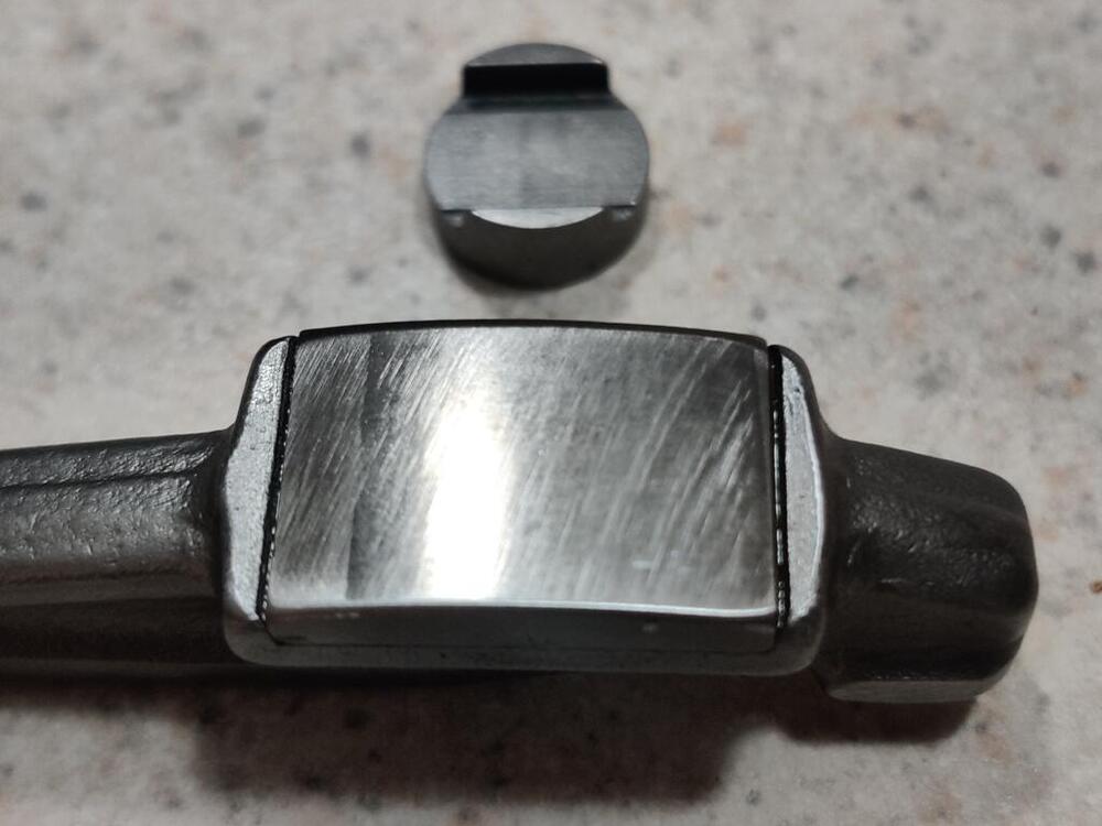
As I mentioned yesterday, the problem appears to be only with the exhaust valves. So, it is with interest that I made the following observation for valves 5 and 6 (with 1 to 12 being from the front of the engine to the back). These rockers are both actuating exhaust valves and are "adjusted to correct valve lash". Note the very different adjuster heights between the two: Wild - right? Well... have a look at this picture - the rocker on the left is the number 6 valve (exhaust) and the one on the right is the number 7 valve (intake): So... what is going on with the rocker on the valve on the left? Do you see how the tip of that rocker appears to be "floating"? And compared to the intake valve on the right, the rocker tip on the left appears to be sitting quite a bit higher (above the retainer) actually: Here is a picture showing the underside of the rocker - see the shiny part where the arm was contacting the retainer? Summarizing what I have found tonight, each of the 6 exhaust valves are hitting the top edge of the Isky retainers. When I was setting valve lash, I was setting it with the rocker arm sitting on the retainer instead of the lash pad. The rocker was floating above the stock .118" thick lash pads on each exhaust valve. During the total of about 1 to 2 minutes of engine operation at low revs, the cam was operating the exhaust valves, initially by rocker to retainer contact, but as the rotation continued, the rocker tip came into contact with the stock lash pad, and operated the valve. And note that the lash pads look very different. The ears on the lash pad of the intake valve (right) are sitting quite a bit further outside the retainer. I removed that rocker and took a measurement of the lash pad: Each gradient is .025". So the reading above is .177" and 7 tenths, or '.175'. These are the lash pads that came with the cam when I ordered it. I am hoping to get lucky here. My plan at this point is to put the .175 lash pads in each of the 6 exhaust valve locations and to modify the undersides of the rocker arms for clearance with the aftermarket Isky retainers. I'll just have to see if between the two, the rocker arms actually sit lower at the tip than before. If so, then I should be able to raise the height of the adjusters for these valves. Fingers crossed.

-
Ok. Yeah, I am going to pull all the rockers and look at wipe patterns, and measure lash cap thicknesses first.
-
Yeah, something really isn't right. I have snapped a bunch of pictures and talked with my engine builder, who did the work on this head. The current hypothesis is that the SI Stainless valves I bought are too long. The installed heights are still visible in black marker on the cyl. head: 1.787" is a lot more than the specification paperwork from Iskenderian (1.700"): The lash cap I pulled out with the one rocker arm I removed last night is .117" and about 3 tenths. Stock is .118". But the "kit" I ordered from Iskenderian has .175" lash pads, (part LC175 - is .175" thick - I looked it up on their site): The retainers currently installed look like the Isky ones. The depth to accommodate the lash pad is notable. Comparing to another exhaust valve which has not had the rocker and lash pad removed, the lash pad (I am assuming also .118"/stock) is "buried" in the retainer. So, the theory right now is that SI Stainless valves are taller than the stock valves (4.620"). I think I will have to pull the head. My engine builder is a great guy and he has provided me with so much value over the years. In this instance, I should have checked the wipe pattern before installed the head, but I did not. As far as I can tell, no damage has been done. So, I think I have been fortunate here.


-
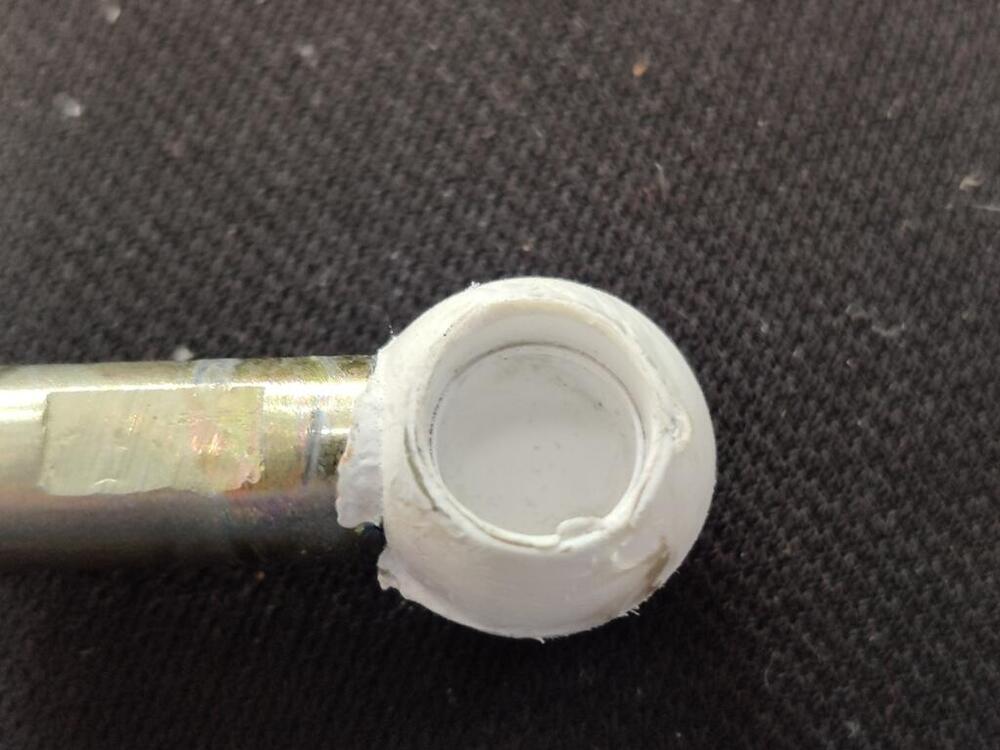
This evening, I examined the needle and seat from the rear carburetor. If found some residue on needle. When I used a wire brush to clean it up and examined the needle (it is metal) closely, I could see a light wear ring. I found two spares I have had for decades and examined them. The needle portion appears to be made out of a hard rubber. I may have bought them new to swap out in my carbs that I used to run on my track car, but never did. Can't remember now. Anyway, they looked pretty much like they were unused. So, I swapped those into the front and rear carbs and reset the float levels using the "wet method". By siting the fuel in a clear tube, they are both set perfectly now. After that, disengaged the balance screw, and set each carb throttle adjusting screw so that I saw the lever move. I set each at about 2 turns in. Then, I turned the key and the engine came to life. Within a couple of minutes, I had the front and rear carbs running on just the carburetor throttle adjusting screws. I turned in the auxiliary shaft adjusting screw to operate the linkage and then adjusted the balance screw to get the air flow the same between the carbs. At that point, I was going check the timing and start adjusting idle speed, but the clatter from the valves was too much and I began to be concerned. So, I decided to shut it off and pull the valve cover. Upon doing so, I was pleased to see no obvious damage to the cam lobes (I had a couple of bad experiences with new cams in my track car). I started checking valve clearances. Just about every one of them did not have enough clearance. I went through and made minor adjustments until - you know it... the last one. For that one, I ran the 14 mm adjustment screw all the way down, but I ran out of adjustment and still couldn't get a .20 mm feeler gauge (it is an intake valve) in between the cam base circle and the rocker pad. So, I pulled the rocker and lash pad. The wipe pattern is not centered and nearly off the front edge. Guess who is going to have to pull all the rockers and potentially change out some lash pads?
-
Hahaha - you guys got me laughing. And good advice, I didn't even think about using water - because everything is new and done right, right? Wrong! Dang water pump. Anyway, I just got in from the garage. I finished my to do list. I did the thing with pulling the oil pump and using a dummy shaft and a drill to pump the oil through the engine. I hate the part where you have to remove the oil pump again and reinstall the distributor drive shaft. I made a big oily mess. But, the engine has been sitting for years after being rebuilt, so I feel better pushing oil through it before cranking it. I didn't want to spin the engine with the starter as long as it take for the oil pressure gauge needle to show pressure without pumping oil everywhere first. After that, I pulled the spark plugs and switched on the starter. I kept it spinning until I saw the oil gauge needle just move a bit. It is amazing how long that can take. I didn't time it, but I bet the starter was engaged for 30+ seconds. After that, I put the spark plugs in, hooked up the leads, looked at the engine bay for about 10 seconds trying to think of anything I had missed for the 30th time today, and then thought "f*** it, let's go". I lifted up each carburetor piston and shot some starter fluid in the direction of the intake. And then I turned the key. I got a bit of life from the engine within a couple of cranks, but when I let the key go it would die. I tried that a couple more times and got the same result. Having a good amount of experience with these carbs, the symptom seemed to be that the two carbs were way out of balance. I operated the main linkage and looked at the resulting movement at each carb linkage. The rear carb linkage was activating, but the front carb linkage was not. I adjusted the screws to get them both moving when I threaded in the main throttle screw. Then I tried again. This time I used the starter cable. It fired up, but having fresh in my mind what @siteunseen had said, I treated the ignition keys like a feather trigger, and when the engine revved up pretty high, I turned it off. I pushed the starters in a bit and tried again. This time it fired up and was holding revs at about 2400. Oil pressure was showing 90 psi (I assume the sender I bought must be the one for the early cars?) Not pausing a second, I swung around from behind the dash to the engine bay and bounced my gaze around to check on key things. Almost immediately I noticed fuel flowing up and out of the air vent in the top of the rear carburetor. So, I shut it down. I am not sure what happened there. I set the float levels just a few days ago. Perhaps I have a bad needle/seat. Total run time was only about 30 seconds or so. I was really hoping to run it for about 20 minutes at 2000, as the cam is new and the rockers have been reground. Really hoping that everything got lubricated enough quickly to avoid any problems. I will need to see what is up with the rear carb and try again.
-
Thanks for the advice. Unfortunately, I put coolant in before seeing it... And, I found out that the water pump (one of the few parts that I did not replace) was weeping coolant. GEEEZ! Thankfully, I have another water pump from a spare engine that seems like it doesn't have many miles on it. So, I had to drain the coolant and replace the water pump with that one, which set me back time-wise. I am taking a break now for dinner. But, I may try to start it after. Add coolant Complete electrical hook up of the Pertronix unit at the coil Install fuel hose on the fuel return line of the fuel rail Repair oil pressure sender wire/connector Remove oil pump and prime engine with oil (using drill and custom made shaft to drive oil pump) Add SAE 20 oil to the carburetors Check torque on cam sprocket bolt Check torque on crankshaft pully bolt Heat engine oil in the pan Install valve cover Add two more gallons of fuel Only a few things left...
-
I think today is "start up day". I have a rather short list of items to complete before I turn the key and see what happens: Add coolant Complete electrical hook up of the Pertronix unit at the coil Install fuel hose on the fuel return line of the fuel rail Repair oil pressure sender wire/connector Remove oil pump and prime engine with oil (using drill and custom made shaft to drive oil pump) Add SAE 20 oil to the carburetors Check torque on cam sprocket bolt Check torque on crankshaft pully bolt Heat engine oil in the pan Install valve cover Add two more gallons of fuel