


Captain Obvious
Free Member
-
Joined
-
Last visited
Everything posted by Captain Obvious
-
 Put me into the "I want a dimmer" crowd too. I run my dash lights just bright enough that I can see them when I drive. I want the gauges to be visible if I need them, but not the main area of focus. LOL... In other words, I need my 50 year old headlights to be brighter than my new LED dash bulbs.
 -
Yeah, it's cool. Of course they were only using it as a simple light pipe, but still. First time I saw they did that, it was a surprise!
-
I believe that is the "light box" for the cigarette lighter illumination lamp. The bulb is in there, and they use a fiber optic cable (the black cable on the left side in your pic) to transfer that light over to the cigarette lighter.
-
Couple tags off the top of my head: @Dave WM @Derek @Serban @tunesnxs @26th-Z
-
I think the ZX distributor I've been messing with has an unbroken magnet. I think I have one here with a magnet in pieces too, but it may be in too many pieces. I'll look to see what I have.
-
For me, it is. Everything I have is stock parts. Spectrum of different years, but all stock. I'd be happy to look into other systems, but I don't have anything here. It all started for me wondering what they did in 78 to allow the removal of the ballast resistor. And the answer is they started including current limiting inside the module in 78. Then av8ferg wanted to be able to mount two different style modules (ZX matchbox and GM HEI) on his car and be able to swap between the two if one of them failed. But when he tried it, he noticed a timing difference between the two. So I thought it might be interesting to investigate that. That's how I got here. I've been poking around inside the stock modules for some time now but figured nobody (other than me) really cared, so I didn't post about it.
-
Agreed on that. Hearing about the popping followed #1 connected or not seems like a distraction from the bigger picture at this point. But it also seemed like something simple to look into.
-
Take a look at the connectors from the injector dropping resistors? That's something that could electrically affect cylinder #1 only. And next time it's screwing up, try swapping #1 and #2 injector connectors. If the bucking now comes and goes with #2 (instead of #1), that could be useful info. The ECU fires all six injectors at the same time, so other than a bad connection to the box or a broken circuit trace inside the box, I cannot come up with anything else the ECU could do that could affect #1 only.
-
-
The "energy starts to fall off" mention is kinda interesting. At low RPM there is plenty of time for dwelll and plenty of time for spark. At high RPM however this is not so true. But the issue is it doesn't matter which ignition system you are running, you are still bound by the same cycle times. By that, I mean... On a six cylinder engine spinning at 6000 RPM, there are 3.33 ms between firing events. In that 3.3 ms you have to charge the coil and then spark that coil. If you want enough spark time, you have to be able to charge the coil fast. And that's where a no-ballast system that uses a current limit in the module would have an advantage. You can charge it faster so you have enough time for adequate spark time. I bet all the systems "fall off at higher RPM's". Unless they are using the same dwell across the entire RPM range, then they would all fall off as dwell decreased at higher RPMS. I haven't measured any of the aftermarket stuff with built in dwell control to see if they use the same dwell time at idle and 6000 RPM. I suspect not. I had all those measurements done for the 77 and 78 modules, but I was just using a signal generator as a simulated input. But after seeing how the modules can react different using the real VR pickup, I'm rethinking the validity of those measurements. I'm not sure using a sig-gen is valid.
-
Yup, low side of the the ignition system triggers both the tach and the ECM (as well as the coil). But since the tach seems to be working without an issue (even when the car is bucking) I'm thinking the low side of the ignition system is OK. And yes, coils can fail intermittently, but there can be other things at play... It might not be a hard black-n-white fail kind of thing. It might be a failure that presents itself above a certain RPM range. Or it might be engine load related since it's more difficult to spark a plug when there is a more dense mixture in the cylinder. Sparks that travel just fine at idle might jump somewhere they don't belong at higher engine loads or RPM. That kind of thing. I'm not expecting a dead short in the cap. Certainly nothing you would measure with your typical VOM. When you get a chance, take a pic of the EFI connections at the battery to make sure you've identified the right wires. Not saying this is electrical, but it's an easy place to start to rule stuff out.
-
Haha!! I find the front face of that thing very "busy". Even without the word "clock", it's just busy. Honestly, it doesn't look very clock-ish to me. Maybe that's why they had to label it?
-
I'd be really surprised to find there was a rev limiter in the HEI module set for 4500 RPM. The Datsun modules I've looked at in depth (77 and 78) have no built in limit and eventually crap out simply because they can't react fast enough. But that point is way above normal operating frequency. Way above. I don't have any of the aftermarket stuff here for analysis, but I'm hoping to get my hands on a couple of the GM modules to poke around with.
-
Well that looks unpleasant. I can't tell from here if it's specifically electric or fuel, but certainly unpleasant. Based on the behavior of the tach, it doesn't appear to be a problem on the primary side of the ignition system. By that, I mean, it does not appear to be related to the ignition module or the ignition switch. It could still be something on the secondary side like coil, cap, rotor. I would check that sort of stuff and also check the condition of the electrical connections between the battery and the EFI system. There are two large spade connectors and a fusible link that come off the battery and are dedicated only to the EFI system. Take a look at those. Here's hoping it something simple.
-
Does that thing really say "CLOCK" on the front of it?
-
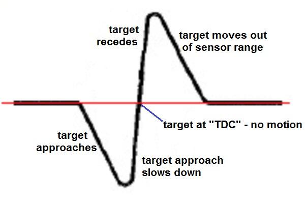
I whipped this up to try to show how the motion of the VR target corresponds to sensor output. As the target approaches, the red wire goes negative. And then as the target recedes, it goes positive. And the sharp transition point in the middle when the target reaches TDC and changes from approaching to receding:
-
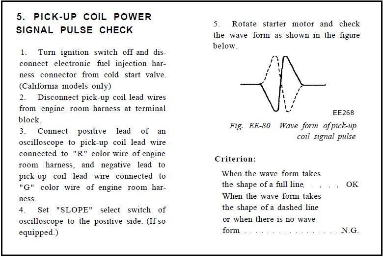
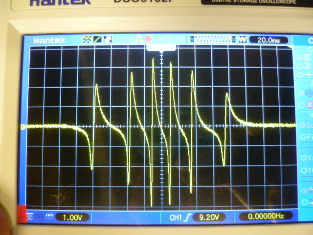
So here's some info on the variable reluctance pickup (used in the Z starting in 74): The only time a VR pickup puts out a signal voltage is when the magnetic field CHANGES. No magnet change - no output signal. And as part of this concept, the FASTER the field changes, the higher the output signal will be. Rapid transitions in the field will result in higher output signals, while more gradual slow changes in the field will put out lower signals. No motion at all, no output at all. Regardless of where the target is in relation to the pickup... No motion, no output. Now let's talk about "polarity": So you've got this VR pickup coil. You put a voltmeter on that sensor coil and it reads zero. Then you bring something magnetic (I'm calling it a "target") towards the sensor and you will see a voltage on the meter. Stop the target close to the sensor, and the meter will drop back to zero (remember... no motion - no change in field - and no output). And then when you move that target AWAY from the sensor, you will again see a voltage on the meter, but that voltage will be in the opposite polarity from when the target approached the sensor. Which direction will the voltage go as the target approaches the magnet? The polarity is determined by the North-South orientation of the magnet and how you have the meter connected. Michael Faraday and all that. On the Datsun ignition systems, the pickup coils have a red wire and a green wire. As a target approaches the sensor, the red wire will produce a negative voltage with respect to the green. And when a target moves away from the sensor, the red wire will produce a positive voltage with respect to the green. Z car polarity: Target moves towards sensor - Red wire goes negative Target moves away from sensor - Red wire goes positive Here's a snippet from the FSM that talks about the polarity and using a scope to check the VR pickup coil. The test procedure is to connect the scope (+) lead to the red wire and connect the (-) lead to the green wire, and then spin the distributor. You should see a waveform that looks like the solid line in the pic: And here's what it looks like on the bench test. Positive input to the scope is red. Negative input connected to green: And here's the waveform out of the sensor when I spin it. Just a short burst spinning by hand. Note that this is an 83 sensor so the shape of the waveform may be a little different than earlier years, but basically the same:

-
Working on it. I was originally driving different modules using a signal generator, but after messing around with that a bunch, I'm thinking that it's not a good representation of the real world situation, so I'm going to have to figure out a way to use a real VR signal. First attempt at setting something like that up worked OK for speed control, but I was using a variable speed DC motor to drive it and I was getting huge amounts of noise on the system. I need to come up with something quieter. Basically, you're asking if I can illustrate the timing changes @Av8ferg saw when he swapped from one module to another, right?
-
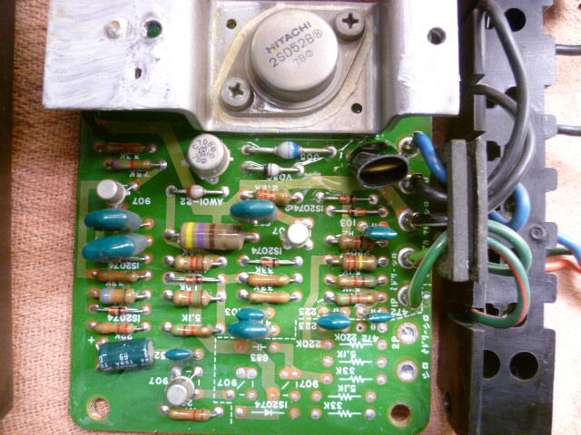
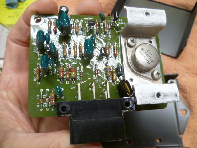
So here are a couple things about the 77 and 78 modules: The cases are electrically isolated from everything inside. In other words, there is no electrical connection to the metal boxes that house either the 77 or 78 module electronics. There is no current limiting in the 77s output stage. That is why a ballast resistor is required to limit the coil current. The 78 module, however, DOES have current limiting built into the output stage which is how Datsun was able to get rid of the ballast resistor for 78. Other than that current limiting and some temperature compensation (which the 77 also does not have), the electrical designs of the 77 and 78 modules are pretty much the same. Since everyone likes pics, here's a pic of the 77 module guts: And here's a pic of the 78 guts:
-
Sure I'm taking questions. Admittedly I'm having a little trouble figuring out the best way to organize my thoughts for this thread. I've done a bunch of analysis of a couple different designs and I'm trying to do a knowledge dump. Problem is I'm not sure the most effective way of getting info out. But absolutely questions would be most excellent.
-
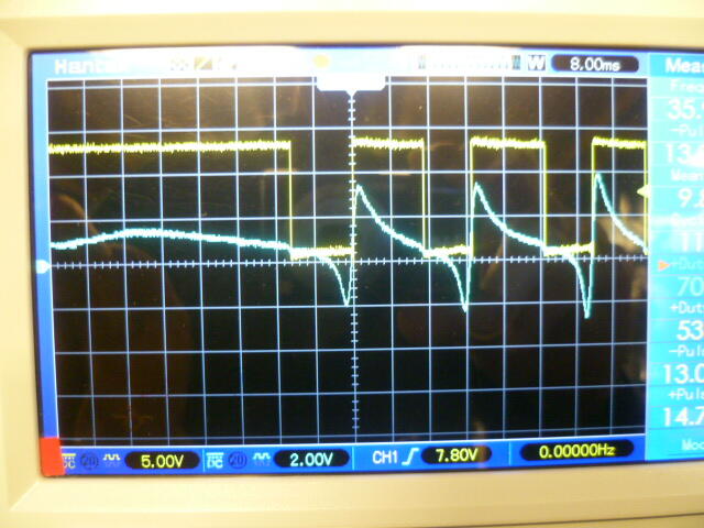
And for discussion, here's what happens if you get the distributor input to the module reversed somehow. Note that the module still fires a spark on the negative to positive transition, but the slope of the input signal at that time is very gradual. Not good for spark scatter and consistency:
-
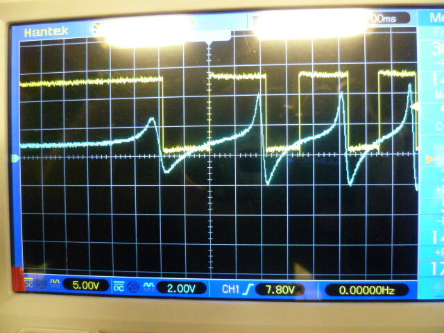
I've been poking around with the ignition electronics on and off and there seems to be some interest in getting into some of the details of how things work. So here's a place to start. Here's a pic of the ignition module signals. The input signal from the VR distributor is in blue, and the output signal that drives the coil is in yellow. Note that when the yellow output signal is low, the coil is charging (dwell), and when that output signal goes high, the coil would fire a spark. Spinning the distributor (by hand) the signals look like this: First think to note is that the ignition module (1977 style) fires the coil on the negative-to-positive (N-P) transition of the VR input signal. Also noteworthy is that the triggering N-P transition VR signal is a steep, almost vertical, slope. This is important because the steeper the slope here, the more consistent the timing will be with less ambiguity and spark scatter.
-
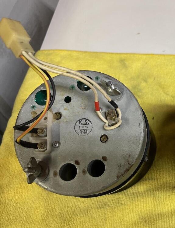
Not quite sure I understand which tach you have (it appears you have two of them?), but the correct tach for your 73 is the style with the loop on the back. The other style (without the loop) will not work in your car without some other modifications. This is the correct style for your car:
-
I will get my geek on and start a thread about such things.
-
https://en.wikipedia.org/wiki/File:Hamilton-appealing2.jpg Hahahaha!!!!


