Captain Obvious
Free Member
-
Joined
-
Last visited
Everything posted by Captain Obvious
-
 Fingers crossed! So the old dead cap either went open circuit, or shorted internally. That style of cap (known as an aluminum electrolytic) has been known to go either way. If it went short, the clock wouldn't run at all. If it went totally open, the clock might work, or might not. Sounds like yours did just that. Hope you're good from here! Too bad about the other clock though. Probably nothing can be done with that one unless you find NOS of the xtal and/or the control chip.
 -
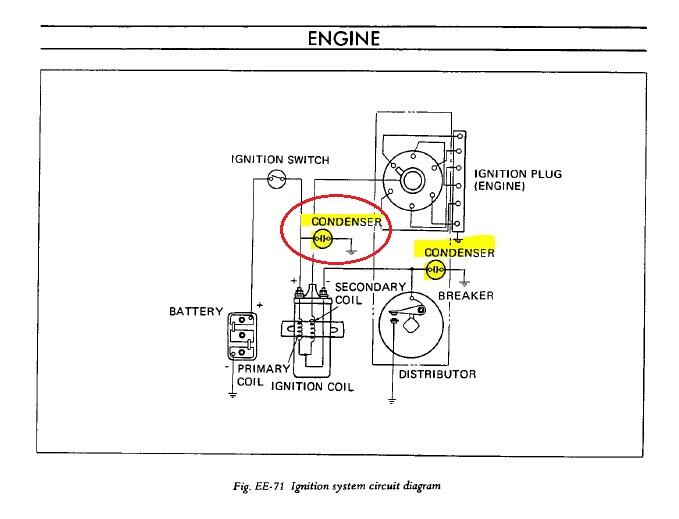
Thanks for the help. I have an incomplete version of the 1970 FSM, but I've been through the EE section. It don't think it shows all the condensers. For example, the circuit diagram you posted only showed the condenser mounted on the distributor. They didn't include the one on the coil attached to the positive side (crudely grafted onto the the diagram below): And they didn't show how the tach connects! At least not until 1972, and it was still cryptic then!
-
Awesome. Thanks!! And your prolific use of pics and documentation has helped me on numerous occasions. Keep up the good work!! I'm currently working on a set of carb air cleaner attachment hardware stuff based on a sketch of yours from years ago. 😊
-
Thanks Zed. I will add condensers and publish a new revision to the diagram shortly!
-
Awesome. Thanks for the help. So it sounds like there are supposed to be four condensers: One on the distributor. One over by the coil, attached to coil (+) One on the back of the alternator, and One by the voltage regulator. Anyone else want to weigh in? Input from people who document pretty much everything? ( @CanTechZ )
-
Hahahaha!! I've been called worse than stickler as well. And that was just today!! 😄 I'm confident with your attention to detail, that stuff I noticed has already been addressed, or will be in the near future.
-
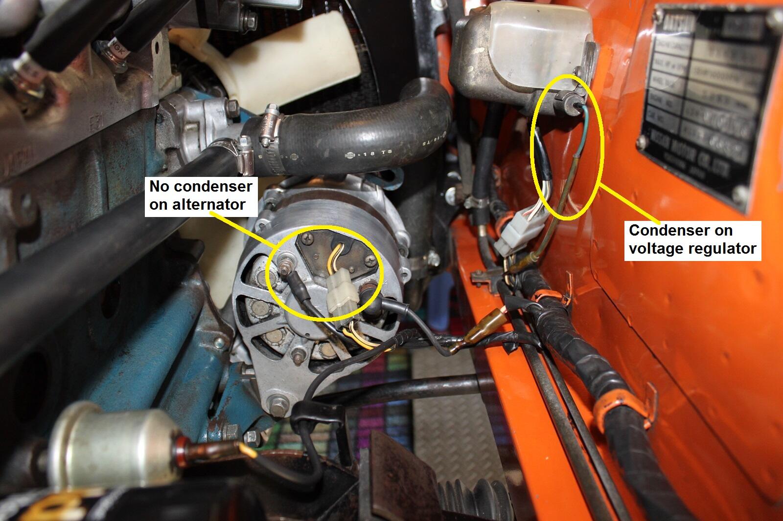
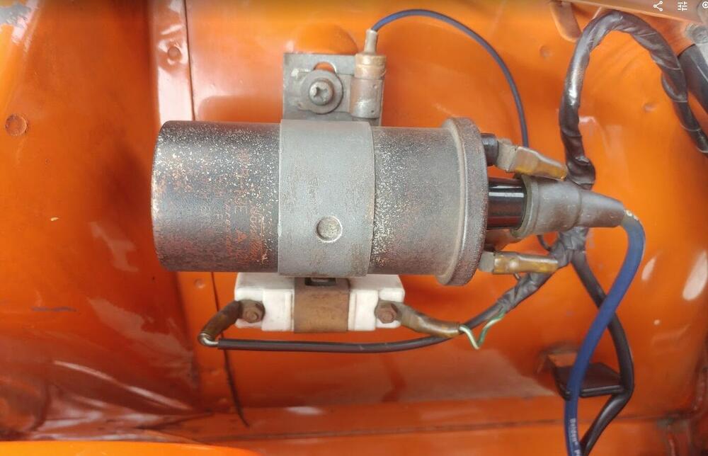
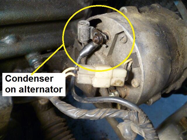
So... Condensers. None of them are shown on the original wiring diagrams, yet it is clear that some exist. I'm working on some revisions to the wiring diagram and I'd like to put the condensers on it. It seems pretty clear that there should be a condenser mounted on the distributor. And it's connected to the points side of the coil (coil negative) like this: Next, it seems pretty clear there should be a condenser mounted over on the coil itself. Question is... Should it be connected to the coil (+), or the coil (-)? Seems to me that it should be connected to the coil (+), since the condenser mounted on the distributor is already connected to the coil (-): Next, is the voltage regulator and alternator. Here's a pic that shows the condenser at the voltage regulator, but there is no condenser on the alternator itself: But I've seen pics with a condenser mounted right on the back side of the alternator, like this: So, my outstanding questions are: 1) To which coil connection (battery side, or points side) does the condenser on the coil make connection to? 2) Should there be a condenser on the back of the alternator? And thank you all for the hoovered pics. I'm pretty sure some of them came from members here.


-
Leaking oil pan gasket? And... Mismatched hardware holding the slave cylinder on?? From you? Stickler for details? I'm shocked!!! Hahahaha!!!! 😁
-
Yeah, that cap certainly doesn't sound healthy. Hope that the new replacement fixes it!
-
Yeah, that thread popped up when I was poking around as well. >> https://www.zcar.com/threads/280z-clock-part.354058/ Yeah, unfortunately, it's sounding like it might be the chip or the crystal. I could probably tell you which of those two items are not working, but it would take an oscilloscope.
-
Excellent. Send pics when you get a chance!
-
Gotcha. Was just making sure the readings you were seeing were "first order" and you you weren't reading something that was fooling your AFM gauge. Something like a lean misfire that can read rich. That sort of thing.
-
I see sites like that all the time claiming that they have stock of old obsolete electronics. I've never actually tried to order from any of them, but I'm skeptical as to the legitimacy of them. Might be completely legit, might be a complete scam. And that's an interesting thought about the programability of the 44001. I guess there is a possibility it's a programmable part. And if so, there's the follow-up question of "when you buy it, is it already programmed?". The 4V drop across the resistor is good. It should be "battery voltage - zener voltage" across the resistor. So if battery is 12 and zener is 7.5, you should see 4.5V across the resistor. if you've got that correct drop across the resistor and the clock doesn't run, then it's either mechanical or one of the remaining components (Xtal or control chip). Your other clock that sometimes holds time and sometimes doesn't sounds more mechanical than electrical. Maybe old lube has turned to tar and is gumming up the works?
-
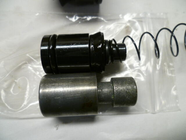
When I rebuilt that old slave cylinder, I included an internal spring. So now I have both internal and external. It gives me guilty pleasure thinking that the two of them are battling it out on my car right now! Hahaha!! 😄
-
You need to fit one of the older heat shields from the round tops so you can use the return springs. And depending on what the climate is where you are located, the water through the carbs isn't a big deal. Good luck with the project!
-
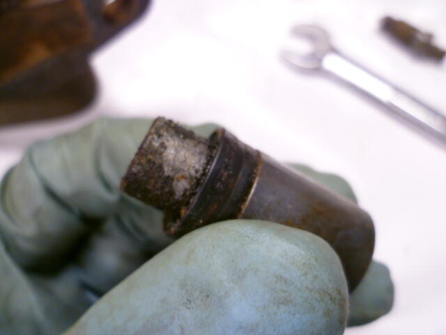
I pulled this off an early car. And the piston looked like this. Note, no internal spring:

-
Sorry for geeking out. I was on a roll. 😄
-
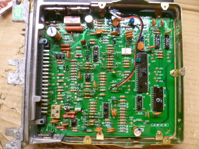
Your analysis of the parts is correct... Resistor, zener, capacitor - Those three parts are used for power supply and regulation*. They are relatively easy to source, and other than the zener voltage, the specs are relatively unimportant. By that, I mean... You could use a 180 Ohm resistor or a 150uF cap. Within reason, the values don't matter. The resistor will dissipate less than half a watt, so a one watt resistor would be fine. Composition (wirewound, metal film, carbon... Doesn't matter.) Crystal, and control chip - Those two are not easy to source. Hope that your problem is not one of those two. The HD44001 control chip does not appear to be available. Probably designed for the application and sold only to the clock manufacturer. And I would try hard to not mess with the crystal. The frequency is a little unusual, and even if you can find another crystal with "close enough" frequency, it's not guaranteed that it would work paired with the electronics inside the control chip. They are used as a shunt regulator system with the cap as a filter. System has about 30 mA quiescent current and therefor a little less than that in compliance.
-
Glad to help. So, are you planning to change over to the round-top style balance tube and throttle linkage shepherds hook? Or are you thinking you'll keep your flat-top balance tube and just cap off the EGR valve? Either way, don't forget that you'll need the round-top throttle linkage that goes between the two carbs. The flat-top and round-top designs are different and not interchangable.
-
I've been inside a non-turbo 83 ECU, and it was, in fact, computer controlled. They were running a Hitachi 6801 embedded controller. And even though I've never personally been inside the turbo ECU, I am nearly 100 % confident that it would also contain a microcontroller as the turbo required much more control than the NA version. So yes, the later years were digital, and computer controlled. Don't know when they made the switch though.
-
Don't forget the "black box" or the "voodoo" part. "Dr. Bosch's Black Box of Analog Voodoo and Wizardry". That's what makes the engine go vroom. * "DBBBOVAW"
-
That's awesome. You totally nailed it!!
-
Is your 260Z a manual, or an automatic transmission? On the manual cars, the EGR relay only controls the EGR system. But on the automatic trans cars, the EGR relay also controls the ignition timing by switching the ignition module to use either the retarded and advanced pickups from the distributor. So, if your car is a manual, then yes... The only implication of removing the relay (and it's associated wiring) is to the EGR system. But if your car is an automatic (or came from the factory originally as an automatic), then there will be implications to the ignition system as well.
-
Haha!! Very nice! I'll PM you! Thanks!!
-
Unless you're really worried about authenticity for your specific build date, I wouldn't worry about it. Basically, it appears there were two versions of that early master cylinder, but the only difference was how they marked the "F" and "R" output ports. Up until around August or September of 1970 the masters had the output port locations stamped with the letter "F" or "R". But then after that, they went to "cast-in" identification marks. I jokingly called them "early early", vs just "early". Haha! The bottom line is that the master cylinder you had rebuilt was used on cars before the fall of 1970, so it's "too early" for your build date. There was some discussion about the changes in the early style master cylinder here in this thread: Page 3 https://www.classiczcars.com/forums/topic/65579-brake-master-cylinder-46010-e4602-up-to-91971/?page=3