


Captain Obvious
Free Member
-
Joined
-
Last visited
Everything posted by Captain Obvious
-
 At least that's the 280-ish version of things. They may have started mounting the TVV up in the thermostat housing for the ZX's. When I get a chance, I'll look through other pics. Unless a ZX guy can come in and answer first.
 -
Took the pic out because I think they DID move the TVV into the thermostat housing.
-
Nice work. Those fuses have given their all. I did the same thing on my car a while ago... Tossed out all the old fuses and cleaned up the fuse block fingers before installing the new fuses. A little contact lube on the fuse block fingers. I would also recommend pulling apart and cleaning all the connections between the firewall harnesses and the console. You know... All the connectors that get corroded because the heater core leaked on them ten years ago. Good luck with the project and here's hoping there aren't too many gremlins hiding under the newer paint!
-
Thank you for watching out for me! I appreciate it! Yeah, Austin... I focus on the good parts. And there were enough of those that I can push the other stuff to the background.
-
I've seen your place... I think you may have started just a wee little bit before that new dash arrived. Looks like all of our places!
-
I didn't dig deep, but I believe there are four different covers. 74, 75, 76, and 77-78. At least that's how it appears according to the pics in the FSM's.
-
Agreed Looks great! Now that you have the timing chain on, you can turn the motor over all the way. Did you spin it a couple times just to watch the valves open and close?
-
The dash caps don't work over the Vintage Dash? What's the problem there? I don't have much problem reaching up under the dash to screw in the speedo cable. As crowded as it is under there, it just seems to work. Maybe it's my long spindly orangutan arms.
-
One of the complications about any sort of fuse identification is that there are differences between years. It's not one size fits all for everything from 74-78.
-
Sheesh! Let me try... The ZX is similar construction underneath to the first gen Z. So you know those frame rails on the Z that run from the engine compartment to under the seats? The ones that rust out and get all pushed up and mangled by jack stands? Well the ZX has pretty much the same thing. Who knew it would be so hard to help the Z community.
-
Riiiiiiight. What's a cubit? * Truly sorry for the non-topical response to the thread, but some things are just mandatory.
-
-
I was thinking the same thing... For wasted spark, you don't need any cam position info at all. And for sequential firing, you don't really need a "good" cam sensor. You get the real "timing" info from the crank wheel. The only thing you are doing with the distributor mounted sensor (cam sensor) for is go/no-go to differentiate whether you're on TDC compression or TDC exhaust. (As an academic aside) I even wonder if you have an O2 sensor, maybe you could even tell the difference between compression and exhaust strokes by analyzing the exhaust gas composition. When you first turn the key and crank the car, it's 50/50 right?
-
With the way the original system works, you cannot simply remove or cap off those connections. In addition to feeding the AAR's idle-up function, they also are for the PCV system. The AAR idle-up system CAN be deleted if you feel you don't need the idle-up feature when your engine is cold, but deletion of the PCV system is more problematic There are two hoses involved that complete a "loop" to pass air through the crankcase. One of them connects from the engine block (below the thermostat housing) to the PCV valve. The other one is the hose that connects the top of the valve cover to the intake duct tube. As part of the way the Bosch L-Jet system works is by measuring the air flowing into that system and metering the fuel accordingly. If you start capping off or venting those hoses, it'll play havoc with your fuel mixtures. You need both of those hoses, or neither. And if you run neither, you need to be willing to accept the issues that come with that.
-
I bet you could make a cheap and dirty version of that ring from a thick piece of rubber to take up the gap. Or buy a silicone tube with the right ID and OD and cut a sliver donut off it. It's not structural, you just need to fill up the gap.
-
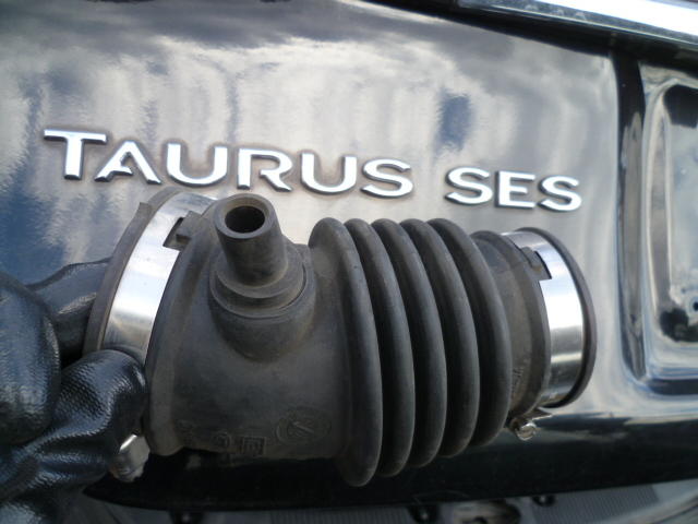
I used one from a Ford Taurus. Details here: https://www.classiczcars.com/forums/topic/57826-afm-intake-boot-tube-replacement-from-ford-taurus/
-
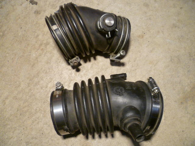
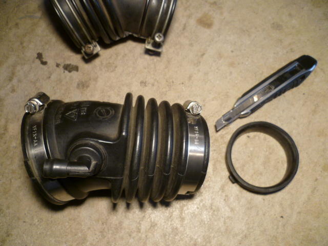
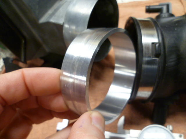
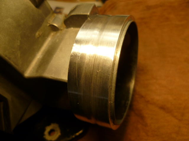
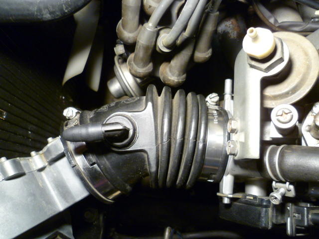
One of my off season projects for this year was to replace my sketchy looking intake duct tube between the AFM and the throttle body. I couldn't see any cracks all the way through, but it's just a matter of time. I know there are aftermarket repros available, but I've always kept my eyes open for other cars that had air intake tract hoses that looked similar to the 280Z. With that in mind, and my never ending quest to find cheap ubiquitous replacements for OEM parts, I nabbed this on off a 2002 Ford Taurus: Here it is compared to the stock connector. The angle is almost perfect, but there are some issues. First, it's a little too long and second, the big end (AFM end) is too big: Taking care of the length is simple. Quick work with the razor knife to remove about a half inch from the small end where the hose clamp was and then put the hose clamp back on a little further up: Second problem... The big end is a little too big. The AFM is 2.75 diameter, but the Taurus hose is 3" diameter: So (on the lathe) I made a spacer ring out of aluminum: Put a little sealer on the joint and press the spacer into place. Now I've got an AFM with a 3 inch outlet instead of the original 2 3/4 inches: Put everything back on the car and it looks like this. Cheap, ubiquitous, and although it isn't stock, it doesn't stand out like blue silicone tubes. One more step in having every molecule of air going through the AFM instead of around it:


-
The theory is that if you use poly on both the front and rear of the T/C rods, you run the risk of snapping the rods from the stress. There are a number of threads here (and on other forums) on the topic, and I believe there are even pics of T/C rods that have snapped off.
-
Oh, and fuzzy memory with no pics, but my trick to getting the ring back on with the column in the car was to wedge something (screwdriver probably) into the upper U-joint area next to the steering coupler donut area to force the steering shaft towards the driver's seat far enough to get the ring back on. IIRC, you can loosen the coupler bolts and compress that lower spring enough to get the ring back on. I try not to "put my back into it" anymore. Bad stuff happens.
-
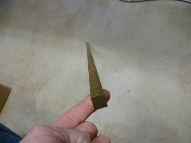
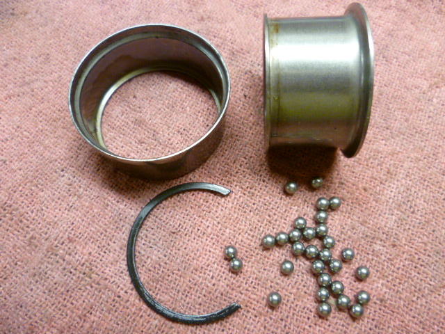
I know you already took care of your column without taking the bearings out, but just so they exist somewhere, here's my photos from the job. Note that if you are going to take the bearings out of the column, you'll obviously need to have the column out of the car and disassembled. Tap the bearings out of the housing if you dare. I used a long chunk of brass rod because that's what I had laying around and used that to tap the bearings out from the far end. The bearings are press fits into the column tube, but it's not a very tight press. Work your way around the perimeter tapping gently and you can walk them out. Here's the long brass rod that I used: Tapping around the perimeter, walk the bearings "gently" out of the tube: Then once you get the bearing assy out, you can pop the retaining ring and lose the balls: There are thirty balls in the bearings so you can count what you have to make sure you didn't drop any: I've been through this job a couple times now and I have added additional balls to the bearings. Not necessary, but I like the feel. I think it tightens things up a tiny bit. Originally there are thirty balls and I usually add one on each end. @Sean240Z added two balls to his and he really likes the way that turned out as well. So now that you're already done and the pictures were late to the party.... Let me know if there are any questions.


-
Parts look beautiful! Only comment... Many people don't recommend poly/poly for the T/C rods. I've heard (read on the internet) that a combo of poly and rubber is better and that's what I run on my car.
-
-
I suspect that your PO thought "well, green is ground, right?" Seems a bit of a leap, but that's all I got.
-
Problem is that tape on the handwheels prevents changes from accidental bumpage but doesn't do anything about the play in the leadscrew threads. Even with the handwheels stationary, the table can still move in X or Y by the amount of backlash in the leadscrews. That's where gib locks would come in. They lock the table regardless of how much backlash there is in the screws. I've added gib locks to a couple machines in my past that didn't have any. Looks like you have plenty of room to add them. Next time you have the whole table off the machine? In the meantime, If you're not chattering and the ease of cut seems fine, lets hope your OK without any locks.
-
I'm not sure if it would be more accurate than using a co-ax, but that technique works too. The most important thing is to lock the X and Y directions down after you get it positioned properly. I took another look at your pics and I don't see gib lock screws. Do you not have that feature? PITA, but you could always just tighten up the gib adjustment screws during the boring operation. Hate to do that though...


