Captain Obvious
Free Member
-
Joined
-
Last visited
Everything posted by Captain Obvious
-
 Thanks again for the input. I appreciate the discussion (which is clearly academic in nature). You said above "the speed of combustion is reasonably constant." If that's the case, then the same amount of time after a spark would develop the same pressure at the same rate regardless of the rotational speed of the engine. That's the whole point we both made above (and it's the theory behind adding centrip advance at all in the first place). I'm saying don't think degrees. Think TIME. The problem is that "degrees" changes with rotational speed. Time does not. If the burn takes 1.3 milliseconds to develop optimum pressure at 1000 RPM, wouldn't it take 1.3 milliseconds at 2000 RPM as well? And 3000 RPM? And 6000 RPM? Why would the burn occur faster at 6000 RPM that would necessitate backing off the advance* at that speed? If the burn rate is constant (in TIME), then shouldn't it be the same regardless of RPM? In other words, the fuel mixture doesn't know or care what the engine RPM is. All it knows is at what TIME it was lit off. If it burns at a constant rate you should adjust the light off to the same TIME regardless of how fast you're approaching TDC. * I say "backing off" because the speed goes up, but the amount of advance does not. It's like volunteering because everyone else in the line steps back. Just a different point of reference.
 -
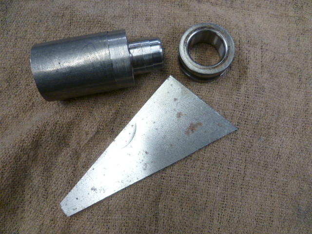
Looks like someone didn't want to spring for cost of the aluminum extrusion that the other guy uses to make these. Has the same "issue" though. The holes are further from the cam than the stock bar. Might matter, might not. Probably depends on how healthy your oil pressure is.
-
Mine too! Thanks for that! Haha!!
-
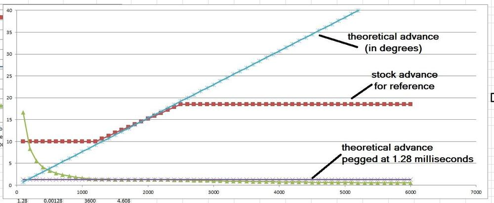
And just because everyone likes pictures... Here's what the timing would look like if you just hard peg the advance at 1.28 milliseconds BTDC. I tried to model the extended curve using the stock slope as a guideline and that's what I came up with. Mechanical only (no vacuum):
-
Using mostly jonbills words (since they were so beauteous)... Since the speed of combustion is pretty much constant, why would there be an upper limit to the mechanical advance? In other words,... Why did Nissan stop advancing the mechanical timing at 2500 RPM? Why not keep advancing the timing mechanically all the way to redline? At first blush, there's no (mathematical) reason to stop. The simple math is the "first order" effect. But things like volumetric efficiency isn't simply math.
-
Yes. That's exactly the question. And thanks for the input into potential answers. I get the need for the advance simply because the engine is spinning faster. That's the easy "first order" part. The more difficult part is "Why is it all in at 2500? Would it be better if it went further?" I guess I'm looking for the second order kind of effect, right? And thanks for that input as well. That website is a good read, but unfortunately, not much info to answer the question about "why did they stop". About the only part that pertains to that question is the table of "Establishing maximum advance requirement" - "Notwithstanding the compression ratio and other factors, the characteristic that determines the maximum advance setting is the shape of the combustion chamber and the position of the spark plug." So it seems that the VE could be a factor. That's one of those "second order effects" I was talking about.
-
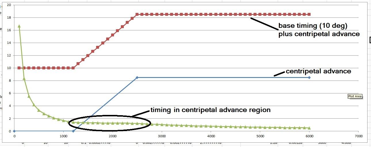
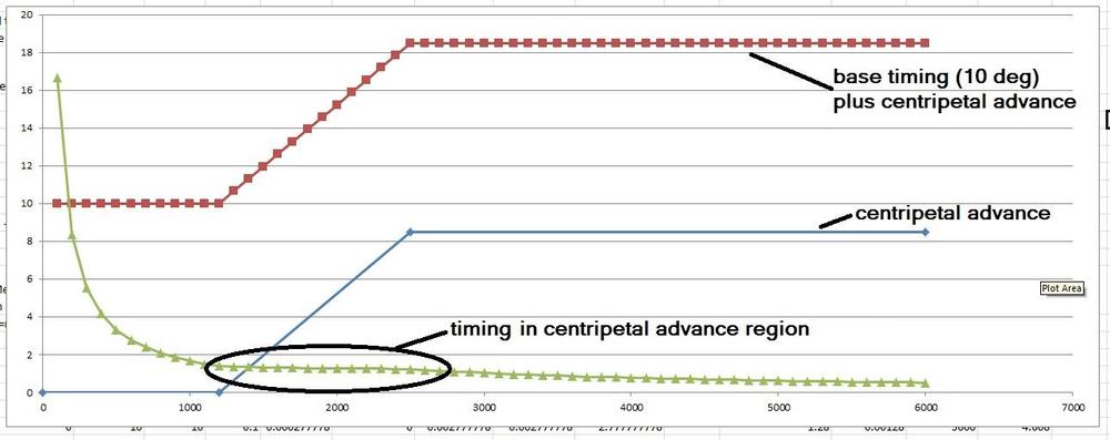
So the recent chatter about timing and distributers has me thinking. The stock distributors include a mechanical (centripetal) advance function and the spec varied some over the years, but as an example here's the spec for 77: 0 degrees at 600 distributor RPM (1200 RPM at the crank) 8.5 degrees at 1250 distributor RPM (2500 crank) There should be no mechanical advance below 1200 RPM, then start ramping up to a max of 8.5 degrees by the time you reach 2500 RPM. Once above 2500 RPM the mechanical advance is topped out and holds at 8.5 degrees all the way up to redline. Specs like this are given in degrees because that's what can be measured and that's what you can see with a timing light. But if you convert the timing specs from the angular domain (degrees) over to the time domain (seconds), it looks like this: At 1200 RPM, the engine is spinning at 20 rotations per second. At 20 rotations per second, each rotation takes 50 milliseconds. If each rotation takes 50 milliseconds, each degree of rotation (out of 360) takes 139 microseconds. So at 1200 RPM, the 10 degrees of base advance provide about 1.4 ms of advance. Doing similar math, if the engine is spinning at 2500 RPM, then each degree of rotation takes 67 microseconds. The 18.5 degrees of advance (10 base + 8.5 centripetal) provides about 1.23 ms. If you go through all the math and plot the results, you come up with something like the following. Notice that the advance value where the centripetal advance is active is relatively flat, but then the advance falls off above that once the mechanical advance has topped out: Studying the numbers, I come up with a relatively constant average of about 1.2- 1.4 milliseconds of advance in the centripetal advance region. So my question is.... Why didn't they continue to advance the centripetal timing above 2500 RPM? Is that just a limitation of the mechanical functioning of the distributor? They just couldn't get the springs, weights, slots, etc to swing a wider range all the way up to redline? Isn't necessary for some reason? Or wished they could have, but just couldn't come up with a cheap enough way to do it?
-
Exactly. You would only need to replace the lower bushing if it's worn. You could hopefully size an upper sleeve such that you could reuse the upper bushing if it was salvageable by reaming. That's why I was thinking that would be a better plan. Less time on the lathe and less risk of introducing concentricity error into the original shaft. Don't run the risk of screwing up the oil distribution spiral groove in the shaft, etc. LOL. So maybe I should go into the distributor rebuilding business? Haha!!
-
Here's what I bought: https://www.ebay.com/itm/25-M8-1-25-Flange-Exhaust-LockNut-Copper-Plated-12mm-Hex/400360273199?hash=item5d3754f52f:g:HJQAAOSwLwBafPRS Copper plated, distorted thread, and they have a force spreading flange on them so you don't need a washer (just like stock). I bought a bag of 25 because I needed them for the broken cam motor and I should have enough left over for my F54/P79 project.
-
I'm sure there are full solid copper nuts available, but most of the ones you'll find are actually copper plated steel nuts. They use the copper plating as an anti-corrosion, anti-sieze coating to prevent the nuts from rusting to the studs. I would recommend using them. They're good stuff. You can also get them in prevailing torque (distorted thread) so you can skip the lock washers and they won't come loose from the vibration and/or changes in temperature. As for the stud portion, I used stainless because that's what my PO had installed there. Just never ever never use stainless on stainless. It's a very hall gall risk unless you know exactly what you're doing.
-
Ha! That's it! Hold it right there! Pronoun trouble... I get it now. It's like helping your Uncle Jack off a horse.
-
Yup. Something just like that. And the plastic part on the bottom should be pretty easy as well. (Says me who's never messed with it!) Haha!!
-
Oh, and BTW, I wouldn't do it that way. I would press (or pin or silver solder or glue or loctite sleeve retainer or something) a 25mm long (or so) cylindrical piece of tubing onto the shaft up where the original bushing wore. Then I would machine that pressed on piece concentric to the shaft leaving it a little larger than the original diameter of the shaft. Then I would ream the upper bushing to fit the larger diameter. Looks like there's plenty of meat in the oilite bushing to make the hole a little larger than stock. That way I wouldn't have to cut the whole shaft down, just the top portion. So what if the holes in the two bushings aren't the same size. Shouldn't matter, right? Of course, never having done it... It's all speculation that plan would work. That shaft goes in from the top, right? Haha!!
-
That's an interesting idea. I bet I could do something with that. Is that where they usually wear? At the top bushing?
-
Yeah, that's really odd. To spend all that time making things flow all nice and smooth and curvy, only to put that huge protuberance thing on the front. Doesn't make any sense to me at all.
-
Body work is about my least familiar areas of expertise, but I was under the impression that anything "silicone" anywhere NEAR bodywork was a really really really bad idea. Big fish-eye risk? Am I overblowing the risk because I don't know what I'm talking about?
-
Send picture of boat and motor.
-
Yeah that fender washer trial didn't work out so good. It looks to me like all the stretch occurred at the center hole instead of the sides (as I believe it should). Looks to me like the clearance on the die set was too narrow. I didn't study the guidelines from that webpage I posted earlier, but my own testing indicated that if the gap is way too big, the material will fold and wrinkle and if the gap is too small, the part will stretch in the middle or shear along the edge like a punch. One other thing that we haven't talked about is the base material... The easiest thing to work with would be something dead soft annealed, and fender washer's aren't. They're heat treated to some spec and then plated. Anyway, your experimentation is keeping you safe. It's a cheap hobby, and you aren't out and about picking up anything unhealthy! I would really try to get some sort of hole in the part before you draw the cup. I put the hole in my test part after and it was a bit of a pain. Would have been much easier if the hole were there beforehand. At least some sort of a centered pilot. Looking forward to the pic of a handful of perfect parts!
-
Nice work. Love it! Nice pile of practice parts. Once you get the parameters right, you should be able to get very repeatable results. At least until the die is worn out. I see a lot of them torn out like my first attempt. I started with a gap that was the same as the material thickness and that was not enough of a gap. I took off about five thousandths and it made a huge difference. I could actually see the material getting pulled down into the die as the pressure was applied. And I found the same issue centering the die since I didn't have a center hole to use as a locating feature either. If I were to do it again, I would put a pin in the middle of the male die to locate the blank and center the male portion of the die in the middle of the other half. However, (in agreement with the suggestion above), I would make the pilot hole a little undersize because I'm not sure if the material will stretch in that area or not. Thicker material might be a little easier since there's more meat there to stretch until it gets so thin that it shears. If you want to know what they started with for the original parts, you should measure the thickness at the flat bottom. A micrometer would be the easiest way. My instincts tell me that the sides will be thinner than the base because the sides are what stretched in the original drawing process. Couple hundred more tweaks and you'll be in production!
-
Excellent. Glad to help. I did a quick web search on the process and quickly came up with the following. This should help you get it right with fewer iterations: http://thelibraryofmanufacturing.com/deep_drawing.html Lots of good pictures and helpful rules of thumb. I should have looked first!
-
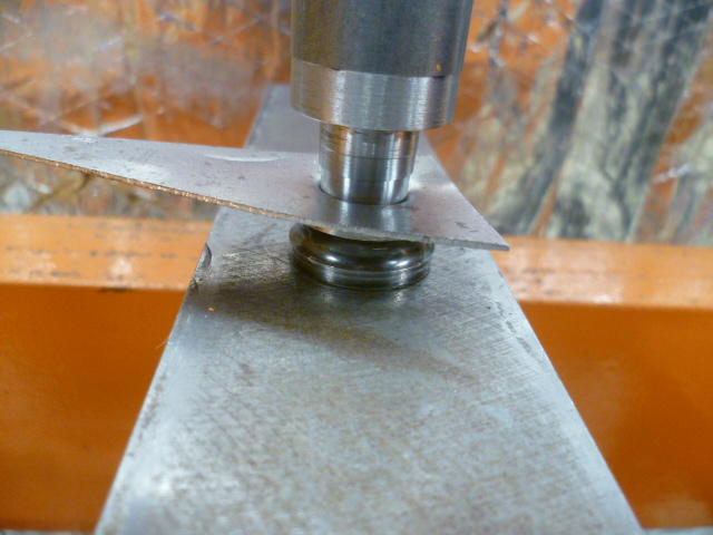
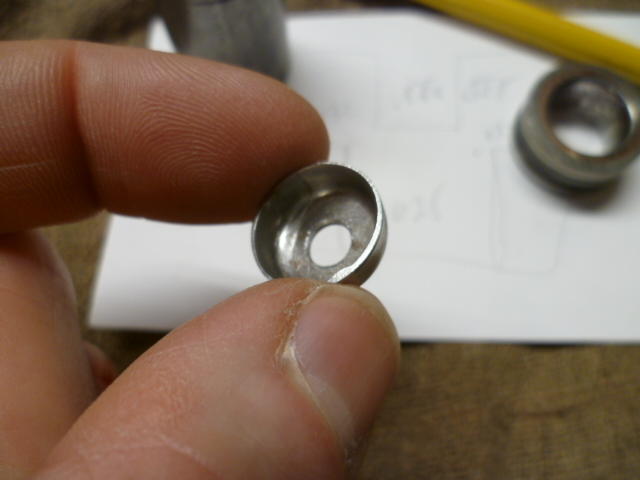
Yes! Yes!! That's the one! Thanks! I was pretty sure it was you or convertt, but finer details continue to slip. They say it won't get any better... So I guess now that you've already answered the process question, that half an hour I spent in the shop this morning doesn't add much more to the discussion. But for the record... For the female portion, I used an old bearing race because its what I had laying here, and it's hardened. For the male portion, I used a previously machined drop of 12L14 steel because it was already machined to close to the size I wanted. For a real product, 12L14 is definitely NOT what you would want to use as pretty much it's only claim to fame is it's ease of machinability. Doesn't heat treat, doesn't weld well, isn't particularly strong, but boy it sure does machine nice. Anyway, hardened race with .625 inch ID. 12L14 male mandrel with .555 inch diameter, and .032 thick steel sheet. It took two tries to get the mandrel diameter correct, and I suspect this is where all the skill and experience comes in. You need the correct clearance between the mandrel and the die for the thickness material you're working with. Not enough clearance and it acts like a hole punch. That's what my first try did. So I took ten thousandths off the mandrel and things got a lot better. And by the way, this forming process is known as "drawing". I assume there's oodles of info on the web if you want to research. On the hydraulic press. My 2 ton arbor press wasn't enough and I didn't want to rip a shoulder out of the socket: Here's the result. Note the tear through on the first attempt and the better draw on the second (lower) form: Trim the excess material off and put a hole in the middle just for show:

-
And then call 911.
-
Haha! Ok, I think I have enough "stuff" laying around the shop that I can at least mock something up quickly and show you what I'm thinking of. And as for the heat treating, it's not quite like that. First - Make sure you know what type of steel you're working with. Not all steels have a composition that will react favorably to a heat treatment process, and even the ones that do, will have a different process depending on the composition. For example, above, you referenced an oil quench... Well that works great for "oil hardening steels", but not so good for "air hardening" or "water hardening". The three most common ubiquitous categories available everywhere are Oil, Water, and Air hardening varieties. I've got a bunch of "O1" (Oil hardening) laying around here and that's what I would use, but it's probably not the best choice for a die like that either. Would be OK, but not great. However, you've got no idea what you've got laying around, so I would just skip the heat treat process completely unless you're sure what you're working with or just want to experiment and see what happens. Second - The temperature you described above is not high enough. Needs to be full cherry red. One simple way to determine if you're hot enough is to use a magnet. The steel will actually lose it's magnetic characteristic when it's hot enough. It will be glowing red and it won't be magnetic. Then quench (using the appropriate method). Third - If the heat treat was successful, the part will be hard. Like real hard. Glass hard. File skates across the surface hard. Problem now is that the part is TOO hard. Too brittle. So you need to "temper" the part to draw back the hardness some. For that you re-heat the part but not as hot. "Straw color" is a term thrown around a lot. Heat the part "to straw color" and then let it cool slowly. After that, the part won't be hard brittle anymore and won't shatter like glass when you put in the press to make your washers. And don't forget that all the while, the glowing part has been oxidizing on the surface and by the time you grind the scale off, what's left is now the wrong size....... So you add to your long bucket list of projects, an argon purged heat treat furnace......... I would skip the heat treat and just make a new set of dies when the first one wears out.
-
Making a set of dies to produce a suitable replacement for that cup washer should be an easy task on the lathe. Without heat treat, I don't know how many shots you would get out of it, but certainly enough to get you through the task at hand. But wait a minute..... Don't you have a lathe? Brain isn't able to pull the details from the corners right now, but someone here on the forum did some cold metal forming recently. Made some dimples in something or made some sort of formed washer? Don't remember who and I couldn't turn it up with a quick search. @ConVerTT , @grannyknot ?
-
Agreed! Me too! And as 240260280 pointed out, it's clearly Klingon. I believe it's three bat'leths bolted together.