


Captain Obvious
Free Member
-
Joined
-
Last visited
Everything posted by Captain Obvious
-
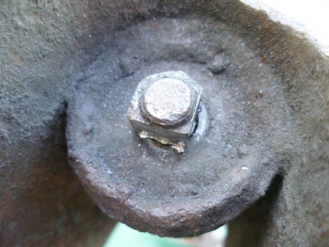
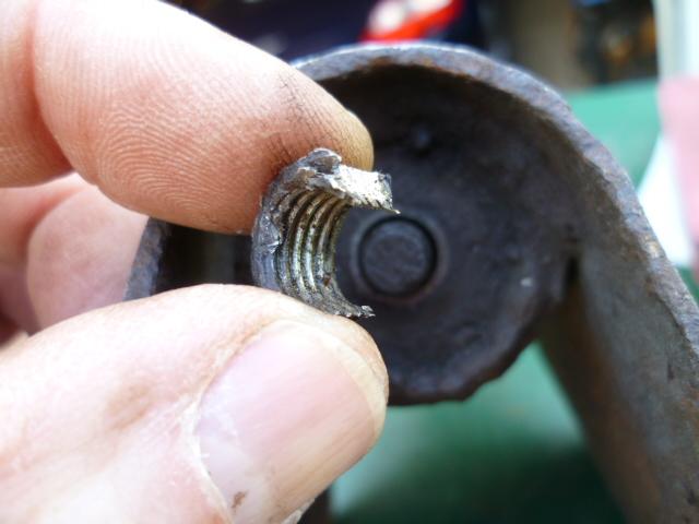
 There is only one significant hurdle to getting the shock out of the bracket and that's the nut on the back side. It's not hard to get to, or hard to turn, but the problem is that there is nothing (except a little friction) holding the shock shaft from spinning. But once you get that nut off, it's not difficult to take the shock our or put it back in. So if you clean up the threads good and put some penetrating oil on it and then hit it with an impact wrench, it should come right off. If you put a ratchet on it, I give it 50/50 that the shock shaft will spin inside the body. Here's the nut: And if the shaft does spin, about the only thing you can do at that point is cut the nut off with a cutting disk. Big ol' PITA: I did two of them, one came off easy with a ratchet and the other did not. After my (lack of) success, I helped another Z guy do the same and told him to skip the ratchet and use an impact gun. His both wizzed off with no trouble at all.
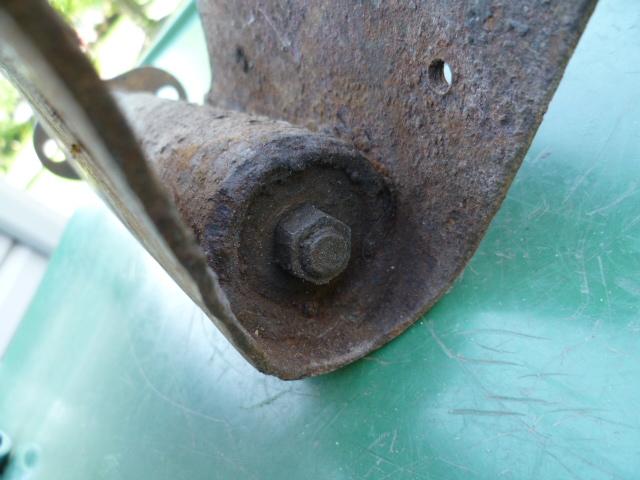
-
Actually if you already drilled a hole and significant oil came out, it really shouldn't matter. But try taking that screw out first and see what happens
-
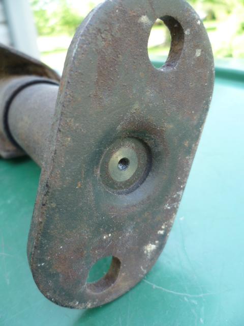
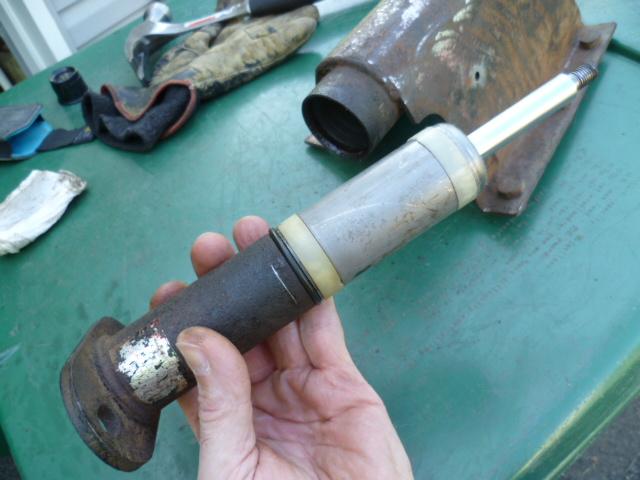
The bumper shocks are high pressure mono-tube struts. If you want to know what that really means, or how they work, or why it matters in this case, let me know and I'll go into the details, but the summary is... Carefully remove the little screw in the middle of the bumper mounting flange. It's holding back significant pressure. Mostly gas, but there might be some oil in there too. Wear eye protection and don't let anything fly. I suggest covering it with a rag once you get the screw cracked loose. After that, the shock should compress and stay wherever you put it. (Until acted upon by another outside force of course.)
-
Hahaha!!!! He's the Hoov!
-
Forgot to mention... Buy a length of piano hinge longer than you need and hacksaw it to length. And if the mounting holes don't line up with the holes on the reinforcing strips. drill new holes that line up.
-
The two wood pieces do not connect together directly. They have the hinge between them. That's because the front piece is hard screwed down. but you still need to lift the rear section to get to the spare. You could probably get a piece of piano hinge cheap at one of the big box stores if you don't have the original piece. And that jars some fading brain cells too... There is a third style hardware used to hold the hinge to the metal reinforcing strips on the wood pieces. It's smaller than M6. Whatever the very commonly used size below that. M5x0.75 maybe? Same screw size they use to hold the center console in place, etc.
-
Haha! Is that one yours? I'm not nearly Hoover status, but I nab good looking pics now and then just because I think they might be useful in the future.
-
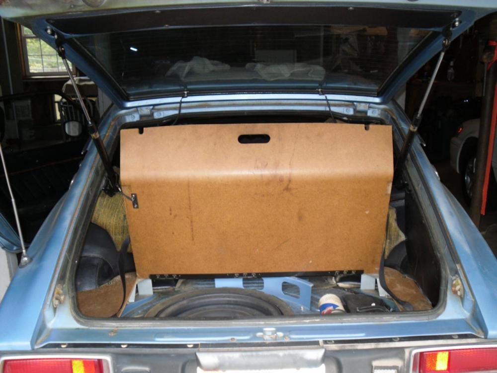
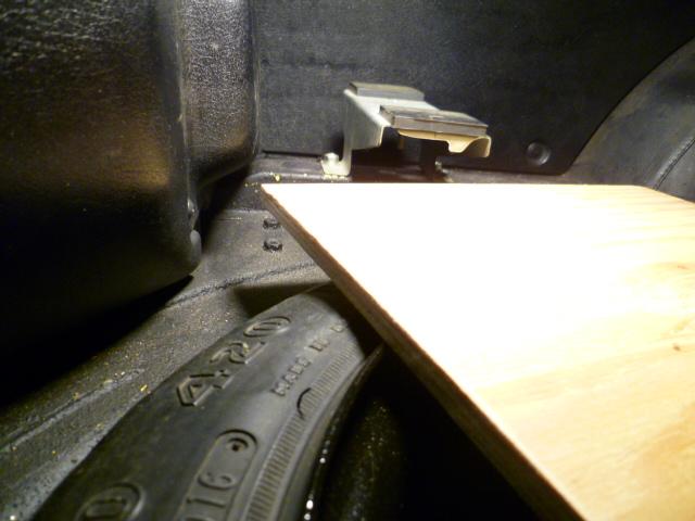
I dug around and turned up a pic that may add a little value. This is the sloped back style false floor so the shape of the "wood" is a little different back by the taillights, but the hinge is still the same. Not my car, but this is how the hinge works:
-
Oh cool. You're much better off than I thought you were and you have all the flimsy brackets. So for the mounting hardware, it's pretty generic. Going from memory here since I don't have my subfloor installed like that anymore... There are two types of hardware used: If there is a threaded insert welded to the bracket, they used the ubiquitous silver M6x1.0 hex head bolt with the Phillips indent in the center. In locations where there is NOT a threaded insert, they used a large Phillips head sheet metal screw threaded straight into the bracket sheet metal. Sorry, but I don't remember how many of each. And yes, there should be a long piano hinge between the two largest pieces. The front portion (right behind the seats) is firmly fastened to the brackets, but the rear portion (over the spare tire) can be lifted up to allow access to the spare. The hinge is the joint between the two. Is your hinge completely missing? I bet it has something to do with the modification that your PO did to the "wood" piece right behind the seats. I don't think I have any pics of what that is supposed to look like, but I think your PO took some material off.
-
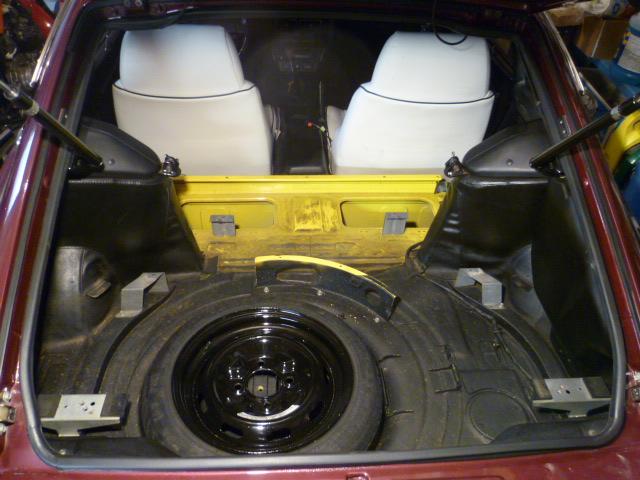
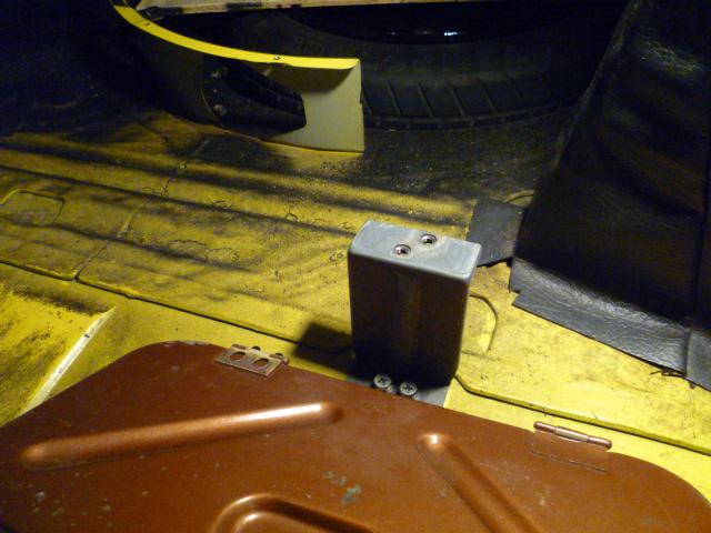
There are flimsy metal brackets that are supposed to hold the raised floor "wood" up off the metal below. Not sure you'll be able to figure out what's going on here, but this is a pic in which you can see the metal brackets: Here's a decent pic of the front most bracket. Ignore the cargo lid. That was the project where I added the cargo hatch lids to my car: Here's a relatively decent shot of one of the rearmost supports: Hope that helps? You got any of those brackety things in your unknown parts pile? Oh, and you're also missing the two narrower "wood" pieces that fit into the side recessed areas way in the back. And lastly, someone modified your front most piece. Added the speaker holes and it looks like they took some material off the rear edge.
-
I can't believe I never measured the length of that nylon strap. Maybe I did and just wrote it down on a piece of note scrap. I've got a pile of them. I've long replaced the blue cheapo nylon strap with a better one with webbing from McMaster. I also upgraded to an adjustable mount on one side so I could adjust for belt stretch, etc. I think I've got my original proof of concept belt in a box somewhere and I'll measure it when I get a chance. And yes... You can remove and replace the strap relatively easily without dropping the diff or even removing the cross member.
Will do. I have a diagram around here somewhere. Some time ago I created a thread about it... I bet all the pics are dead because of photosucket. In the meantime before I find the details... I had the whole engine compartment harness out of the car because I was doing other changes as well. One of the other changes I made at the same time is I converted over to the internally regulated alternator and I put my headlight relays where the voltage regulator used to reside. Not sure what year you're working on, but on the 280's, the voltage regulator is on the back side of the relay bracket just forward of the battery. That's where I put my headlight relays. I'll dig up my details and post them.
I'm skeptical about the validity of taking photos out the windshield showing how my headlights look, but if I get the chance, I will do that. I'm not sure it'll add any value without having a fixed "point of reference", but I'll give it a shot. The best thing would be to have your car next to mine and we could compare. We should figure out a way to make that happen some time. I did my 280Z relays using a hybrid method of old wiring and new wiring. I'm still utilizing the original fuses in their original location, but the switches on the steering column are only controlling relay current now, not the high headlight current. So for me, one of the nice things is that the two headlight fuses in the fuse block are still labeled correctly, one per side.
So going back through the issue... Problem started simply because you left the coil wire off the distributor. You're thinking that damaged the ignition module and then with all the cranking with a damaged module, it badly flooded the engine? Is that the basic progression of events?
Steve, do you know if the original GM system was actually designed to utilize two throttle bodies (with two injectors), or just one? In other words, was your system originally designed to run one TBI but is now running two smaller injectors in parallel instead and letting the O2 sensor provide the feedback to level everything out? Back when I was current with my GM stuff, there was just one throttle body and they used that system on some of the in-line engines. I don't know if they ever did two of them on a V-engine or something like that.
From my Fiero days (88), I have a small amount of experience with the system a little older than what you're working with. I don't know if they called it the same thing in the later cars, but back in 88, they used a system they called "ALDL", which is Assembly Line Diagnostic Link. And the most common software used to talk to it was "WinALDL". Not sure if any of that is what you're dealing with in the later version you have, but that's what it was "way back then". I (thankfully) know very little about the GM EFI, but I do remember there was a there was a clear flood mode. Thankfully mine mostly just worked fine and I didn't have to troubleshoot. I did jumper the ALDL pins once or twice to blink the stored codes out on the check engine light, but that's about it. In any event, glad you made progress with the issue and things seem to be pretty much back to where you want them.
Agreed. I didn't put my relays in the interior (they are out in the engine compartment), but I used four relays. One per side per beam. Not only is it a more fault tolerant system, but it also minimizes the voltage drop in the switching system. Down sides are the obvious cost and complexity, but relays are cheap and the complexity is a once and done thing. With the relays, I find my old original incandescent bulbs to be quite enjoyable on a dark road.
Cool. I know was jumping in and assuming I understood what you were talking about and I'm glad I didn't just make things worse. So from the fact that the 510 latch has a longer handle, I'm thinking the 510 latch is mounted further from it's hood edge than the Z's? You need that longer handle so you don't have to reach so far under the lip for your fingers to hit the tab?
Haha! Glad to help. I didn't get it at first either.
And I put a furry blue sour cream container in the trash can today that I should have recycled. @Dave WM and I are clearly wildmen living the American dream!! In my own defense, out of the corner of my eye, I think I saw it move under it's own power. I didn't want to stick anything in it to clean it out.
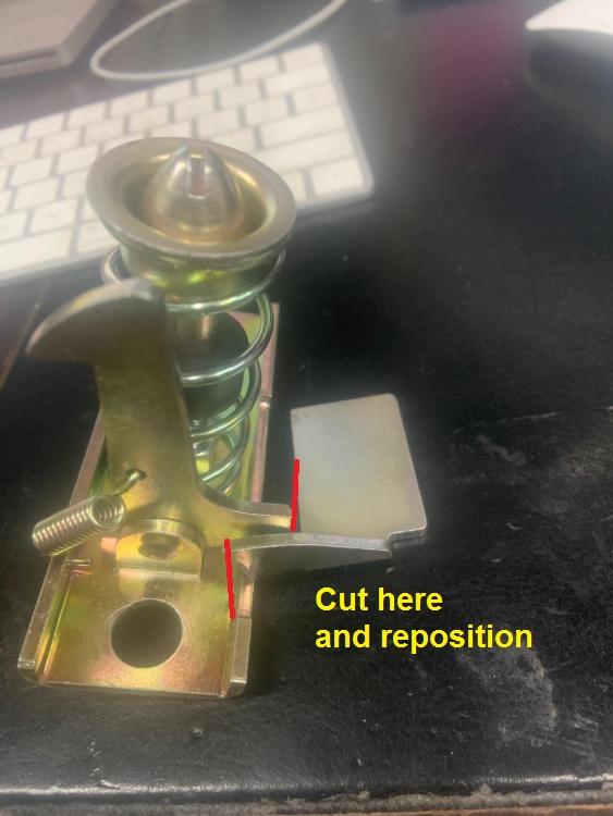
Racer, I think you're misunderstanding what needed to be cut. The little grab handle you reach in to unlatch the hood was too long and hit the cowl. He cut the handle off and then re-welded it in a "shorter" position. At least I think:
 Thanks for checking. Makes me wonder what they include in their kit for the 280's. A question for someone else who bought one of those. Thanks again and good luck with the build!
So why should we have environmental restrictions in the US that they don't impose in other countries? Someone answered that question earlier... "US, Europe are the cleanest on the planet, and have improved drastically." Sounds like if you want to live in the cleanest part of the world, you have to work at it and pay for it. If you allow a free-for-all with no restrictions, you get what people are complaining about in other parts of the world. There are compromises between many competing priorities that have to be made in order to enjoy the benefits. And I agree with several of the posters above when it comes to classic cars. I have zero fear that there will be restrictions on my use of my classic Z that would hamper my use of it. I'm not alarmist. I'm not worried about my Z.
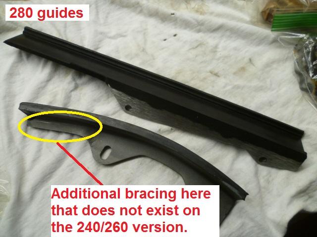
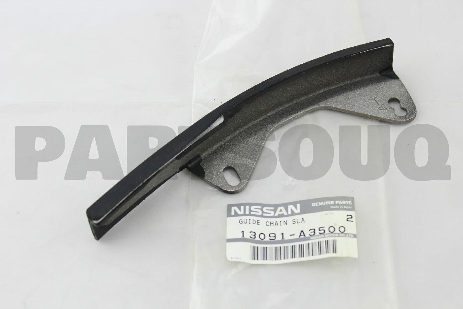
Thanks. So which slack side guide style came in the 053-90300 kit you purchased? Did it come with the 280 style, or the 240/260 style? It's more than just the hole shape at the bottom. The upper portions are different as well. I don't know if they are the same overall length or not, but the metal back-up support plate is different. I'm having a hard time describing it, so I marked up a pic. This is the 240/260 version: And this is the 280 version. Note the additional meat on the metal support:
Thanks for checking. Makes me wonder what they include in their kit for the 280's. A question for someone else who bought one of those. Thanks again and good luck with the build!
So why should we have environmental restrictions in the US that they don't impose in other countries? Someone answered that question earlier... "US, Europe are the cleanest on the planet, and have improved drastically." Sounds like if you want to live in the cleanest part of the world, you have to work at it and pay for it. If you allow a free-for-all with no restrictions, you get what people are complaining about in other parts of the world. There are compromises between many competing priorities that have to be made in order to enjoy the benefits. And I agree with several of the posters above when it comes to classic cars. I have zero fear that there will be restrictions on my use of my classic Z that would hamper my use of it. I'm not alarmist. I'm not worried about my Z.
Thanks. So which slack side guide style came in the 053-90300 kit you purchased? Did it come with the 280 style, or the 240/260 style? It's more than just the hole shape at the bottom. The upper portions are different as well. I don't know if they are the same overall length or not, but the metal back-up support plate is different. I'm having a hard time describing it, so I marked up a pic. This is the 240/260 version: And this is the 280 version. Note the additional meat on the metal support:


Important Information
By using this site, you agree to our Privacy Policy and Guidelines. We have placed cookies on your device to help make this website better. You can adjust your cookie settings, otherwise we'll assume you're okay to continue.