


Captain Obvious
Free Member
-
Joined
-
Last visited
Everything posted by Captain Obvious
-
 I believe the straight threads are just normal metric pitch stuff. The tapered stuff is BSPT, but I think the straight threads are typical metric.
 -
Dug up a pic courtesy of @jfa.series1
-
Where do the cowl drains dump out? Do they terminate in the area the you're trying to keep dry?
-
That's very cool. Great thinking and adapting!!!
-
LOL! So no bonus points, but it sounds like you don't need them. Beautiful car!
-
Exactly. Sometimes a cigar is just a cigar.
-
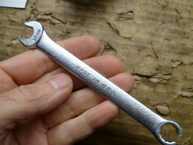
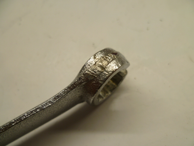
Oh, and by the way... Great minds think alike! Here's some pics of mine I made who knows how many years ago. I used a cheap-o 12-point though because I figured that since I was going to be clamping the crap out of it with vice grips anyway, I opted for the maneuverability instead of the strength: Battle scars on the outside from all the vice-grips:
-
Nice car! Bonus points* if you're still running the flat top carbs. * Not that it means squat, but it sounds impotent.
-
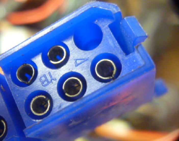
Most of my hands on experience is with the later years (280's), and on those, pretty much all the connector stuff on the Z's was made by Yazaki. Logo is sorta an arrowhead and it looks like this: Some of the fuel injection stuff used on the 280's is AMP. But other than that, it's probably Yazaki.

-
Hahaha!!!! I also rotated the pic so I could get a better view of the number.....
-
So nobody wonders why I said that? Nobody is even going to ask? What? Am I the only person out there in the whole world that looked up the part number stamped on the handle on Jim's awesome transmission spinner device? Just me?
-
Well actually, according to Bob Bitchinn, the answer is "two". Apparently he rolls big joints.
-
-
I can't wait! You know it's not going to run first try, right? You know that, right? I'm no expert on such things, but here's what I would do. 0) Make sure you have a fire extinguisher and a spotter/helper with you. 1) disable the fuel injection system and pull the spark plugs. Crank it over a bunch like that first. Just to get the oil circulating and listen for grossly incorrect noises, etc. To disable the FI system, I would disconnect the fusible link that runs to the positive battery post. And to look for oil pressure, you should be able to pull the oil cap on the valve cover and watch for oil coming out of the holes in the camshaft lobes as you (your helper/spotter) crank the engine. 2) Once you've got oil flowing, put a timing light on it and you might be able to get it spinning fast enough on the starter to get your ignition timing somewhat close to target. 3) Then once you've got oil flowing (and maybe timing close), pull the starter solenoid wire off and just hang on the key for a little bit and listen to the fuel pump running. I can hear the difference in sound of the pump when the load changes on a full pressurized rail. 4) Then once you've got oil, spark timing, and fuel... Put the plugs in, reconnect the starter solenoid wire on, reconnect the FI fusible link, cross your fingers... And give it a go. And call me so I can hear it running in the background!!!
-
LOL. I like it!! That's a great idea. So what is it that opens your garage door now though?
-
Cool. Things are better when the numbers line up. So it sounds like the needle heater can deal with 240mA on a pulse width modulated basis, but not forever. It's all about heat and average power.
-
Well that's what I get for relying on memory... I just took a quick look at a fuel gauge, and I got the heater resistances wrong. The heaters (both regulator and needle movement) resistances are about 50 Ohms each, not the 100 Ohms I mentioned above. The SENDER unit is 90-100 when empty, but the heaters in the gauge are about half that. If the regulator is closed, it will pull about 240mA. And if the fuel sender is at zero (full scale), the needle heater will pull another 240mA. So if you run the gauge without the regulator heater (no ground connected), the needle heater will see a constant 240mA at 100% duty cycle (not the 130 I mentioned above).
-
The gauge current will actually drop completely to zero when the regulator opens. You're looking at a wildly swinging PWM signal with the digital current meter on your power supply and I didn't see a zero fly by on the gauge, but it does actually cut off completely. And that comes back to the burn out the gauge question... In normal operation, the sender resistance could be zero. So in normal operation, the gauge heater will pass current proportional to it's heater resistance which is about 50 Ohms (which I believe is about 90-100 Ohms). But it doesn't pass that current 100% of the time. It's pulse width modulated and the average power is cut down because of that*. When you operate it without the regulator ground connected, it's running 240mA 130mA at a 100% duty cycle. And it sounds like given enough time, that's enough power to eventually heat up the nichrome wire to the point that it doesn't like it. *I didn't write anything down, but memory says the regulator runs at about 50% duty cycle once it's warmed up.
-
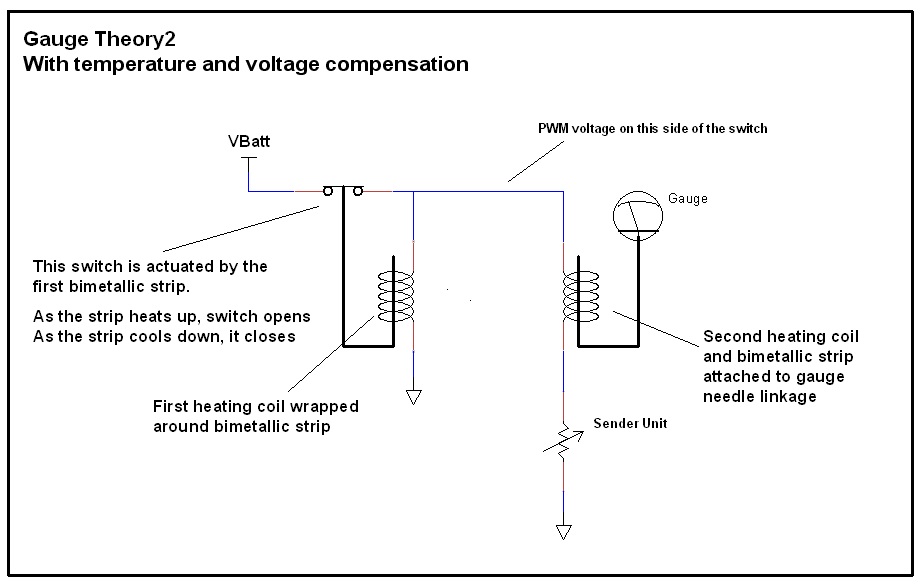
Glad to help. That temperature compensator/regulator is really an ingenious little detail. I should really put together that "how the gauges really work" thread I suggested some time ago. In fact, I suspect the OP's issue with his gauge is dirty contacts in the regulator portion of his fuel gauge. (But I haven't officially suggested that yet because it's jumping the gun until you work through the other possibilities.) So, you had previously mentioned (in another thread) the caution about damaging the gauge if you didn't connect the ground. That ground connection is the low side of the regulator heater, so if it's disconnected the PWM will run full bore 100% to the sender unit. But I'm surprised to hear it's enough power to burn out the sender heater. You've seen this happen? It's only about 240mA 130mA.
-
There will be some DC current draw variation due to the change in resistance of the sender unit, but the approx. once-per-second fluctuations in the current draw while you aren't changing the (simulated) sender resistance, that's not due to any divider. That's the temp/voltage regulator built into the switch. You're seeing the PWM draw from the regulator contacts opening and closing. You won't see this when you first hook up the gauge because the regulator is cold. And a cold regulator will run full bore (100% duty cycle) until it heats up.
-
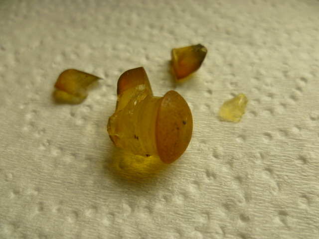
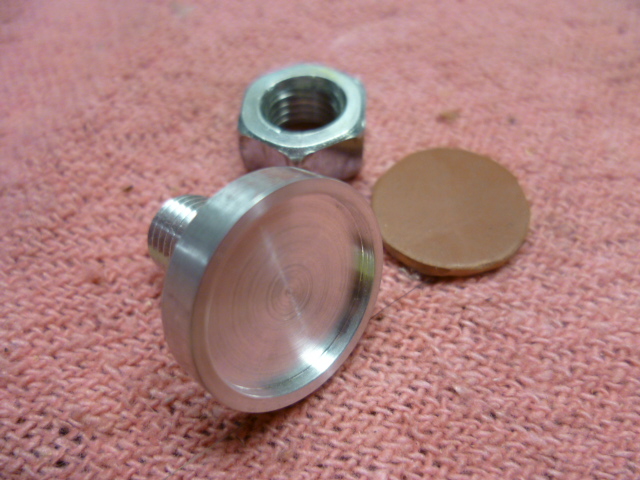
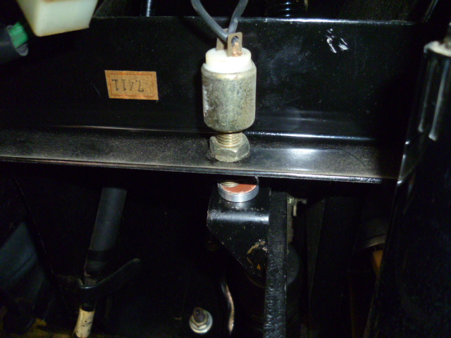
My brake switch bumper turned to dust a couple years ago. Looked like this: So, I chucked up a piece of metal on the lathe and made this: Glued the little rubber pad into the recess and put it up under the dash. A completely unreasonable and unprofitable amount of time later, I have this: Next time, I'll use a quarter. With maybe a couple layers of hockey stick tape over it to prevent any metal-to-metal noises.
-
The only times I've messed with that spring and bracket was while I was bolting the throttle body onto the snout on the intake manifold, so I don't know if there's enough room to get in there and deal with it while the AFM and rubber tube are in place or not. You might have to take off that stuff in order to fit hands down in there to put the bracket and spring in place. Here's hoping you don't have to take too much off to get in there.
-
And here's a snippet showing where they originally connected the carbon can purge line:

-
1 - Yes, the vacuum port on the throttle body that points forward is the one that supplies vacuum to both the distributor advance and the carbon can "DIST" (distributor) port. From the throttle body nipple, to the "T". Then after the "T", one side goes to the distributor and the other side goes to the control signal port on the carbon can. 1a - Yes, if you aren't running EGR, just cap off the other vacuum nipple. 2 - The "purge" line on the carbon can goes directly to the intake manifold. One of the ports on top that is always straight-up manifold vacuum. 3 - The bracket for the return spring mounts under one of the four Allen head bolt that hold the throttle body to the intake manifold. As mentioned above, the bolt is the one on the lower right. Here's a pic of an upside-down throttle body and you can see where and how the bracket mounts:

-
The parts that don't look like they were plated... I think they missed the vats completely. Looking at the rest of the stuff, I don't think it's possible they went through the same process and came out looking like that. But glad they found the missing bits! That would have been no fun to replace all that!


