


Captain Obvious
Free Member
-
Joined
-
Last visited
Everything posted by Captain Obvious
-
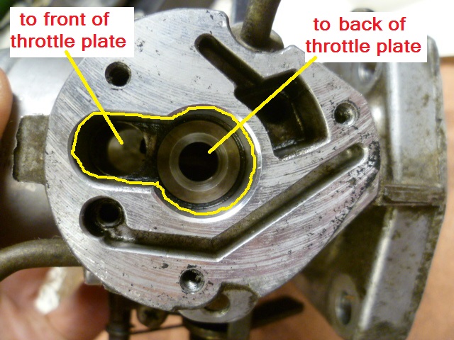
 You can get away with that on the ZX because of the different BCDD design, but on the 280Z, you have to block off at least one of the internal holes.
 -
Sorry, I wasn't paying enough attention. On the 280, you can't just slap a plate on the bottom to block off the BCDD. If you do that, you'll have a huge passageway around your throttle plate:
-
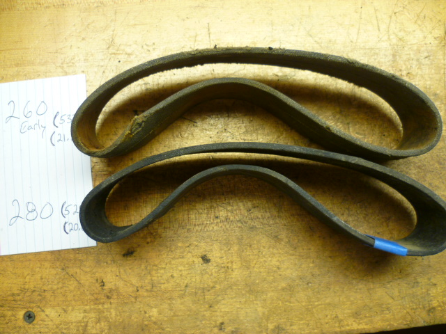
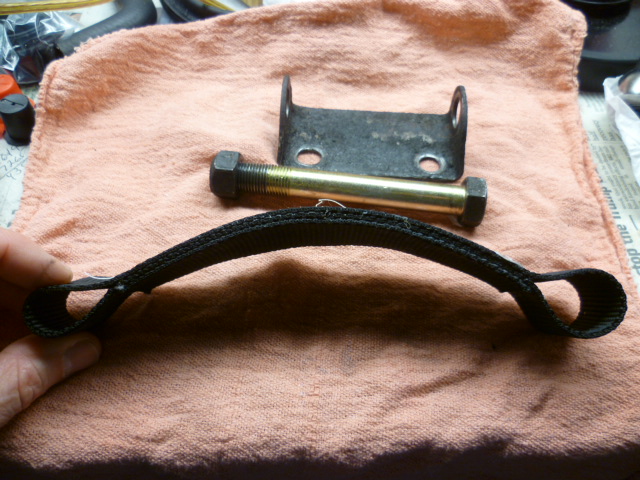
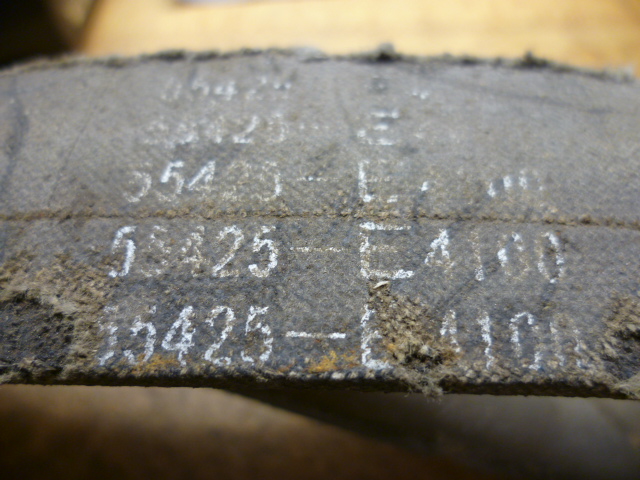
All the pics are dead, but here's a thread I put together a bunch of years ago about my diff strap project: https://www.classiczcars.com/forums/topic/55955-my-new-diff-mount-and-strap-project/ And here's a couple of the pics that don't show up in that thread anymore. Here's the older and newer side by side: I found early strap to be 537mm and the later strap to be a little shorter at 529: And here's what I ended up making for my car. I used heavy duty nylon web strap and made my own:


-
Right. When you blip it, fuel pressure should spike up. But revving and holding probably won't raise the pressure much. Maybe a little, but not much. And as for holding pressure on the system.... There are two things. First, on the supply side, there should be a check valve screwed into the fuel pump the hold pressure towards the rail. And second, on the return side, the fuel pressure regulator should hold pressure in the rail. The exact pressure number on shut-down is a little fuzzy because of the timing of events, but it should be "non-zero" and probably "between 15 psi and 25 psi". We could get into the reason why it's hard to predict on engine shut-down, but it's academic and probably not necessary for what you're working on.
-
But with no load on the engine, it really doesn't (shouldn't) take a lot of throttle to get the RPM's way up sitting in neutral. Point is... Sitting in neutral there won't be a lot of change of manifold vacuum at any steady state RPM level. And because of that, steady state fuel pressure should be about the same. You should see a small increase in pressure as you raise the engine speed, but not much. You'll see a blip nearly to 36 psi when you goose it, but steady state should be about the same regardless of the engine speed assuming that speed is constant. Does that make sense?
-
It does respond that fast. You should see the pressure blip up when you goose the throttle (because there is a quick blip reduction of manifold vacuum).
-
Fuel pressure should be 36 psi minus manifold vacuum (in psi). So for example, if manifold vacuum is 16 inches of Hg, then the fuel pressure should be (36 - 7.8) or about 28 psi. The conversion for inches of Hg to psi is about half. One inch of mercury is about a half psi.
-
The symptoms of breaking up worse under load do make me think of an ignition related issue. Your different colors on the plugs might be a tuning issue as well, but load dependent misfires would have me looking at ignition stuff first. Plug wires arcing to ground somewhere, or coil wire arcing over to someplace it should not be going. Have you put in new cap/rotor/wires?
-
Great stuff! Funny though, (in my immature 13 year old brain) this me chuckle :

-
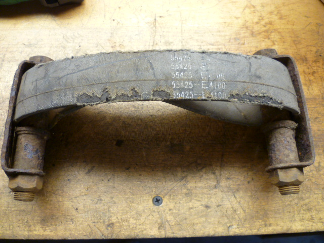
Not sure it really matters, but I think the 55425-N4300 is the strap for the 280's with the R200 diff. if you've got a 240, then I believe you want the 55425-E4100. My measurements indicate that the two straps are different lengths.
-
Yeah, I'm not saying that's the problem, just tossing out ideas and possibilities. From the other stuff you mentioned, like differences between plug groups, it certainly sounds like it could be an issue elsewhere. Happy hunting, and hope you get it running the way you want it!
-
Looks great. So when are you going into production? It sounds like there are a couple other owners who want those. Aint that the truth!!
-
Exactly. The only way the port into the side neck of the canister gets down into the carbon part of the can is through the little hole you plugged with a screw. I suspect that many of the original purge valves built into the cans don't work correctly anymore and I think your use of a new aftermarket purge valve is a cool innovative way to get around that. You just missed the mark a little bit with your original implementation. Glad to help.
-
I think I did that already. That's what my first three posts were. My first post was pointing out that your modification does not work. My second post was telling you how to fix it and actually make it work. My third post was additional info for you to help you understand why what you have done does not work.
-
That video was done by someone who knows how the system works. I'm not asking if he knows what the purpose of the purge valve is. I'm asking YOU what the purpose of the purge valve is. What is the purpose and why would you ever want it to open?
-
Yeah, if it's as simple as it sounds, it's likely that your wiring change is not what's causing the problem. However... Note the word "directly" that I used earlier. The reason I said that is because there may still be a problem with the 72 distributor you threw in there which is causing a problem. Points not set correctly. Dwell issue. Spark scatter from bushing wobble. Leaky condenser killing spark at higher RPM... Lots of problems could be caused by the distributor but might not be caused by the wiring modification you made. Point is, I'm not yet giving your 72 distributor a thumbs up, but I don't think the problem is your wiring change. Does that make sense?
-
I was actually talking about either the stock purge valve, or the aftermarket one you put in. Doesn't matter. Why did Datsun put that valve there? What is it's function? Why would you want to have that valve open? Ever? Why didn't you just cap off all the lines at the engine and pull the carbon canister off your car? I'm trying to confirm that you know what the purpose of that purge valve is.
-
OK, then let's start simple.... Why would you want to have the purge valve open? What would be the reason to ever do that? Explain to me why having the purge valve open is a good thing.
-
Adding that extra valve the way you have done it does not "work like stock". It does nothing functional at all with respect to vapor mitigation, and in fact, could actually cause engine damage. The stock system does this... The fuel vapors that come off the tank and temporarily stores them in the carbon canister. Then under certain circumstances while the engine is running, those vapors are pulled back out of the carbon canister and disposed of by burning them in the engine. That's what the stock system does. The system, as you have modified it does this... The fuel vapors that come off the tank are stored in the carbon canister. Until the carbon in the can becomes fully saturated and cannot hold any more vapors. After that point, any vapors that are pushed into the tank are simply vented to atmosphere through the fiberglass filter on the underside of the can. Also under certain circumstances while the engine is running, the purge valve will be opened and an unknown and unpredictable amount of fresh air will be pulled into the engine leaning out the fuel mixture an unknown and unpredictable amount. That's what you have now.
-
Oh, and to answer your question "I guess my end question is, how can I tell if this Duralast sensor is NPT or BSPT?" The answer would be "Use a thread pitch gauge". The 1/8 NPT is 27 threads per inch, while the 1/8 BSPT is 28 TPI. The two of them should be easily distinguishable with a gauge because the thread pitch is different. But if you don't have a gauge, you should be able to hold the two threads against eachother (with the teeth meshed with eachother) and see the difference. If the thread pitches are the same, the teeth will mesh perfect. But if the pitch is different, they will not.
-
So just make sure I understand everything... You bought an adapter that has female 1/8 NPT threads on one end and male 1/8 BSPT threads on the other end. And the Duralast sensor you purchased threads nicely into the NPT female end of that adapter. Is all that correct? And also, so how does that new adapter fit into the block? Unless I missed something, you didn't mention that.
-
Actually that's not exactly the case either... If your cap seals to the can now, you have effectively capped off all the vacuum lines. However, if the cap does NOT seal to the can (which is what I suspect), you have now introduced a vacuum leak of unknown volume when you are at light cruise on the gas pedal. The size of the leak will be determined by how well the plastic cap seals to the canister. And I suspect that cap seal is not that good since you took out the diaphragm material (because it interfered with the screw head). You will get good idle performance because the purge valve is closed, but at partial pedal position, when the purge valve is opened, you may run way leaner than designed. Not a good situation. OK, I think I've given this enough thought for today.
-
If I understand correctly, your modification should work fine as is and I'm thinking your issues are not (directly) caused by the single point mod. So on the 73 harness, there are two black wires that go to the distributor for the points, right? And you have shorted both of them together and then connected that pair to the single wire coming out of the 72 distributor? If that's the case, it should be fine. But, stranger things have happened. Can you put the original 73 distributor back in just to see if the problem goes away?
-
But I don't want to come off as if I'm poo-pooing the idea. I actually think it's a pretty neat concept to a common problem. So... How would you utilize that Dorman purge valve to accomplish what you were trying to do? Take the screw back out and silicone the cap (with no diaphragm) onto the canister so it doesn't leak. Maybe use the original diaphragm along with silicone to help with the cap sealing, but cut a half inch hole in the center of it first. You want the cap to seal to the canister but you do not want the diaphragm to be able to block off the little hole where you had the screw. One other detail is that you have ruined the metered orifice in the canister by running the screw in, so you would need to use the spare can you picked up instead of the one you had the screw in. So bottom line? Replace the can with the spare (with no screw this time) and put the cap on in some fashion such that it completely seals along the perimeter, but cannot and will not ever block off the hole in the post in the center.
-
I'm really sorry, but unless I'm missing something, this modification does not work. Sure, it will get rid of your previous vacuum leak, but only because you have effectively plugged all of the hoses. You could have just capped off the vacuum lines at the throttle body and the intake manifold with rubber plugs and the end result would have been the same.


