Captain Obvious
Free Member
-
Joined
-
Last visited
Everything posted by Captain Obvious
-
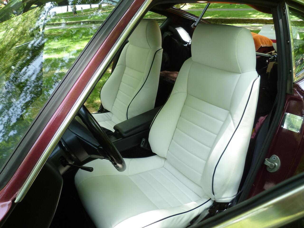
 I don't know how severe the bump was in 75, but on my 77, the left side was tight dealing with the seat bolster up against the trans tunnel and converter bump. Some people perform the catalytic converter "hump bash" (technical term). Which, as the name implies... You bash the hump down with a BFH from inside the car to make more room for the driver's seat. I put Fiero seats in my 77 and passenger side was a lot easier than the driver's side. I did not perform any hump bash operations because I told myself that I might want to put a pre-muffler resonator in that location some time in the future. That was ten years ago maybe? Haha!
-
I like it! Sounds like a good winter project! Hope the project goes well with no surprised.
-
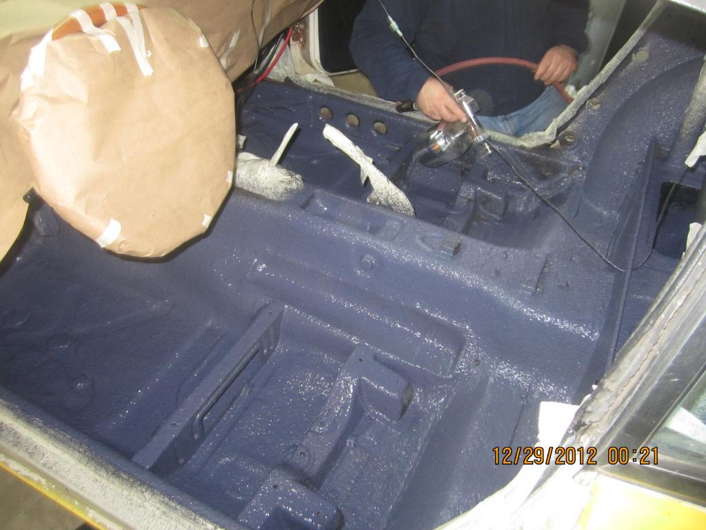
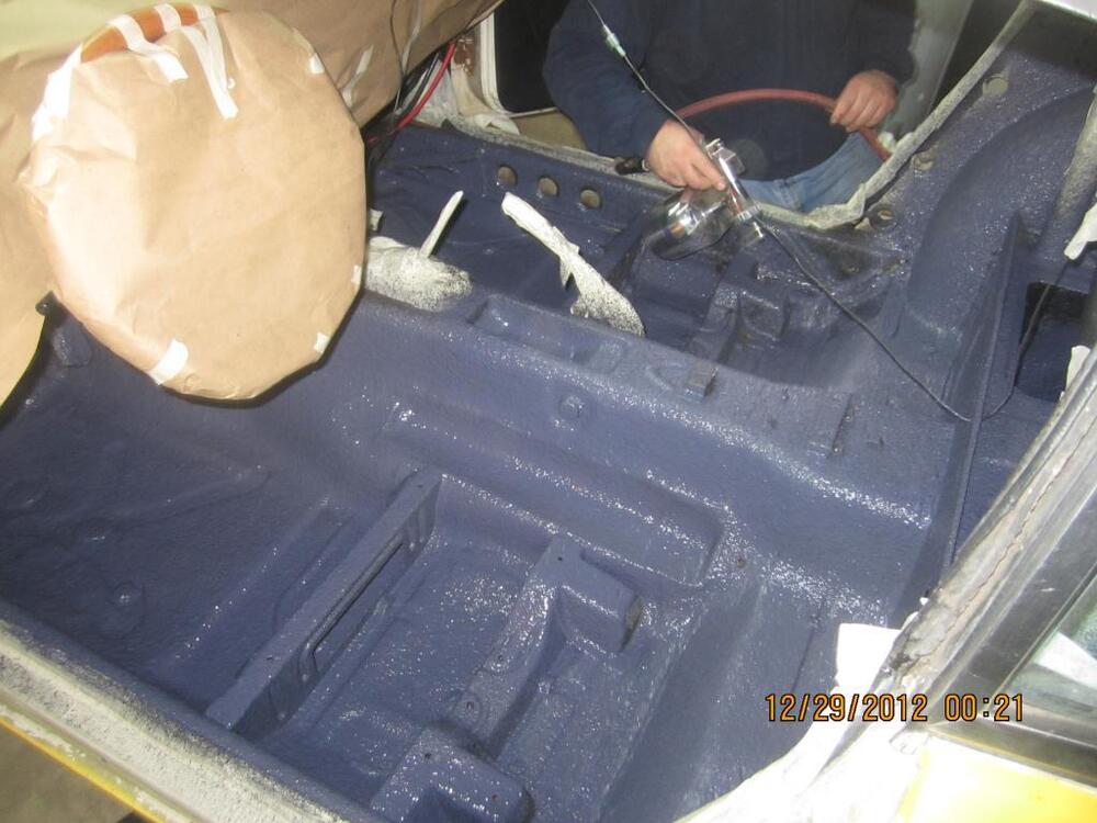
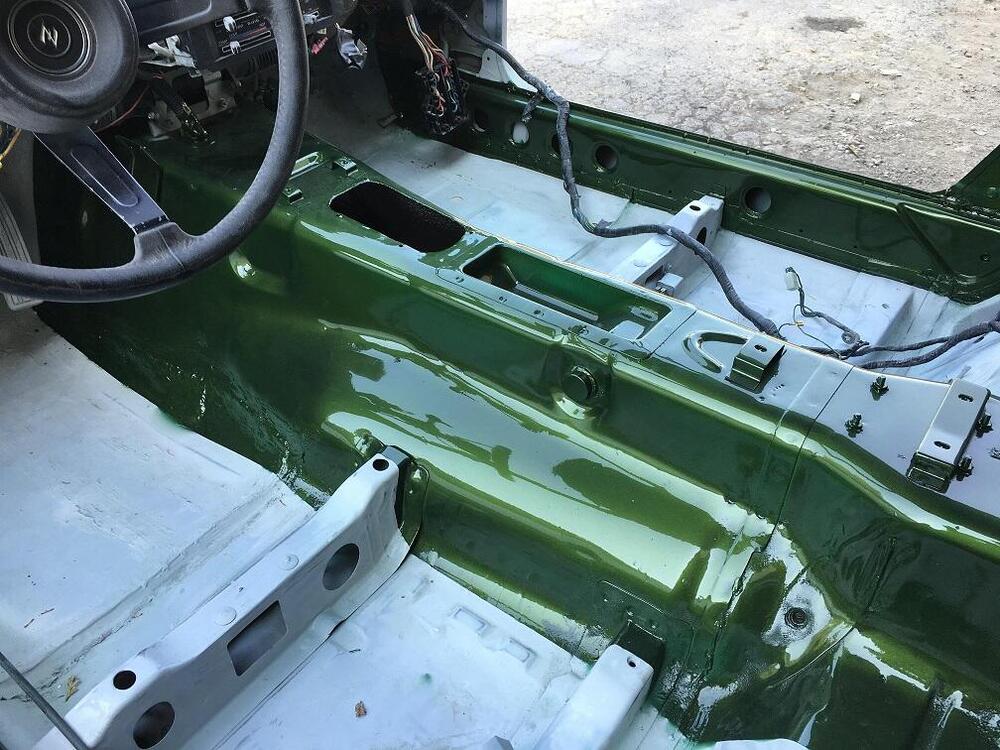
That should make it easier. On my 77, the bump into the interior for the catalytic converter (if equipped) looks larget than what you have on yours. Here's a pic of a 75 or 76 with the bump: And here's a 77-78 bump, hump:
-
"Supposedly up to 10% more." Perfect. So I'm not sure about the openings where the carbs mount. I haven't measured them to compare, but I do know that the carb throats themselves are the same between round tops and flat tops. They are all 46mm, so it seems like all the intake manifolds would have that same hole in them. I've got both varieties of intakes around here somewhere, but it will probably take me some time to find them and measure.
-
Has all your seat work to date been on the right side seat? I ask because the left seat may be a little more complicated if your car has a bulge in the floor for a catalytic converter. It started in CA first, but not sure what year they started that.
-
Actually thinking about it a little more, I think you could put your round tops on the N36 without a coolant leak. There were coolant holes in the previous intake manifolds for the 3-screw round tops in 72, but they gave up on that idea and ran coolant direct into the carbs starting in 73. I don't think there are holes in the carb mounting face of the N36 manifolds. There are "teats on a boar" holes in the back side of the carbs, but no matching holes on the manifold side. So you're back to being able to say that you have the best flowing intake manifolds installed. If I had the manifolds off for some other reason, I'd put the N36's on just because. Not sure if I'd go through the trouble just to switch, but if you had it apart for other work as well.
-
I haven't tested any of the manifolds, but I'll go out on a limb and say that you will not notice any difference at all. And if there is some minuscule difference, you would only be able to pick it up on a well tuned dyno with multiple runs. That said, I've heard the same thing about the N36 manifolds. And if I've heard it and you've heard it, then probably lots of other people have heard it too. The point of that is... If you switch to the N36's, you would be able to say things like: "Lots of people say the N36's flow the best of all the intake manifolds, right? That's why I put them on my car." So, I'm clearly not providing any technical expertise on flow characteristics, but I CAN tell you that you would use the same thick phenolic spacers you are currently running with your E36 intakes. I can also warn you about one potential pitfall... If you are running coolant through your E36's now, you will have a problem with the N36's because they have a hole on the face where the carbs mount that will leak of you run round tops there. I suspect you are not running any coolant through your intakes currently, but thought I would bring it up just in case.
-
At quick glance, I would interpret the torque spec for that nut to be 59 ft-lbs And no... I don't think that nut could handle that.
-
Glad to help. Hope you get it all figured out. If I were energetic, I'd reload those pics into that old thread. Maybe next time I'm allowed out.
-
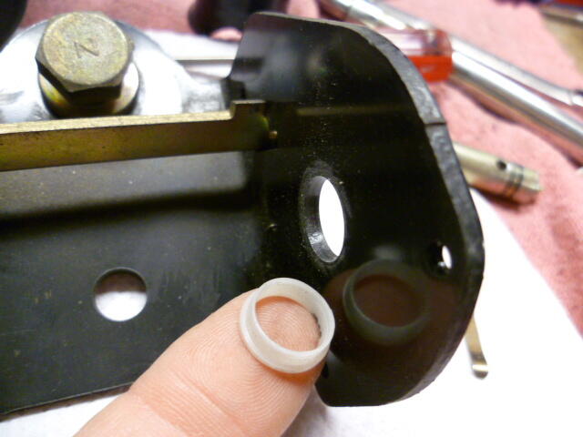
Most of the strut shafts I've messed with are chrome plated carbon steel, not stainless. But I don't know for sure what Koni uses. As for "Is it a mistake?".... I guess that kinda depends on who you ask. If you ask ME, the answer is "Yes, someone at Koni made a mistake." Why do I say that? Because this problem keeps happening over and over again with those parts. It's clear that something is wrong and it's not just you. But WHO at Koni made said mistake, or what KIND of mistake was made is up for debate. It's either a materials specification mistake or a documentation mistake. At bare minimum, there should be warnings in their documentation about this type of failure and how to handle the installation process to avoid the problem. Maybe specify (or even supply) some lube. Maybe switch to different hardware. Something. But the fact that it just keeps on happening to other new purchasers is an indication that something is wrong. I think you should take it up with Koni and see if there is any relief available. There was a Koni guy around here at one time. @KONI Lee
-
Hope that helps!
-
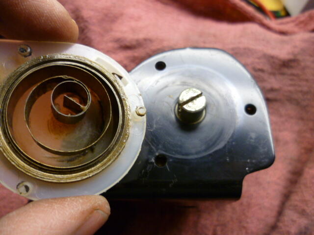
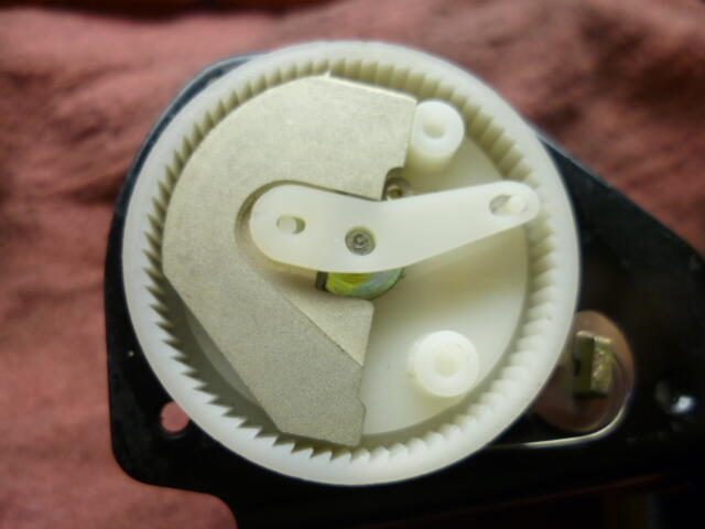
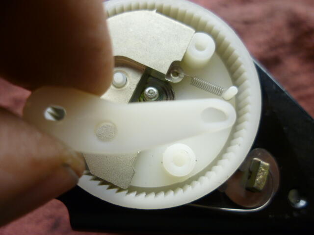
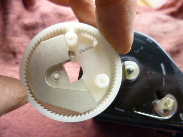
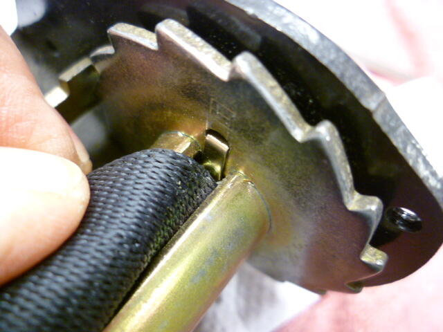
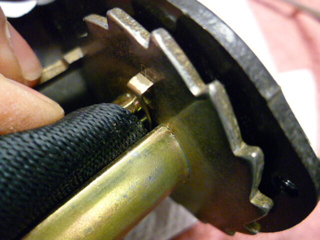
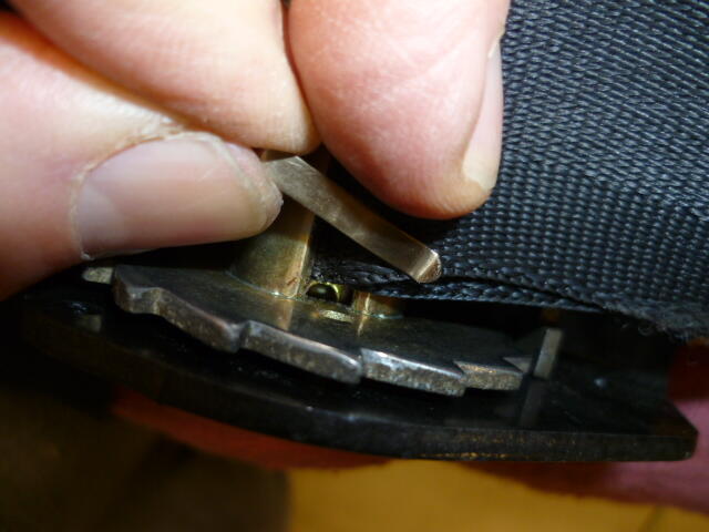
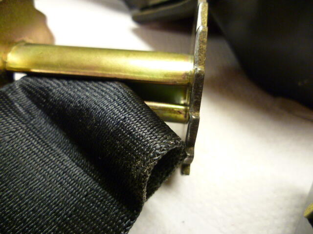
Here's the pics I took of my seatbelt disassembly. First, a caveat... I didn't take these pics with the intention of using them for a how-to... I just had a dead belt with badly frayed webbing and thought I would take it apart to see how the whole thing worked. I figured I would take some pics along the way so I could refer to them again in the future if I ever needed to. Second, these pics are from a 77, and I have no idea if they are the same on other years, but hopefully they will add some value. I also have pics of the assy before I popped off the side covers, but I'm not including those since we all know what that looks like. Step1 - Wind the seatbelt as far as you can into the retractor assy to minimize the tension in the retractor clock spring. In other words, let the retractor spring pull in as much belt as it can before you loosen the side cover. Once you have the belt fully retracted, use a small screwdriver to pop off the side cover. Note that there will still be some spring tension so be careful. Do not let the side cover spin wildly after you pop it free. Hold the cover with your hand to make sure it does not spin and after you get the last retaining pin free, carefully rotate the side cover to release the spring tension. Count the number of turns it takes to release the tension so you know how many turns to wind it up when you put it back together. Interesting to note that the retractor spring function is completely separate from the rest of the assy. That means for those of you guys with retractor spring problems, all you need to do is pop off that one side and replace the spring. You don't have to mess with the latching mechanism at all. In fact, for the shoulder belt portion, you probably don't have to take the assy out of the car. You can probably do that with the assy still attached to the strut tower. Here's the retractor spring and cover after releasing the spring tension: Step2 - Pop the side cover off the other sire. Here's the latching mechanism side: Step3 - Pry off the little support arm: Step4 - Pry off the latching mechanism: Interesting to note that there isn't a whole lot that can go wrong with the latching mechanism. Probably the simplest thing that can go wrong is the tiny release spring can come off or break and then the latch will operate too easily or will not release at all. Step5 - Pull the retaining pin that holds the take up reel into the bracket. Look down into the belt reel and you will see a retaining pin. Here's the pin fully installed: Here's the pin pulled halfway out: Here's the pin pulled all the way out: Step6 - Pull out the center axle shaft and the take-up reel will come free. The belt is held into the reel by the center axle, so once the axle is removed, the belt webbing can be removed from the take-up reel: Reassembly is the reverse of disassembly.
-
What happened to the threads on your struts is called "galling", and it is an unfortunate occurrence when using hardware like you have there. Especially the Ny-Loc nylon insert anti-vibration style of nuts. The worst situation is stainless Ny-Loc nuts on a stainless shaft. Just don't do it. Here's some discussion about such matters in this thread. On or about page 14: https://www.classiczcars.com/forums/topic/61542-koni-sports-for-classic-zs/?page=14 Here's some links that talk about thread galling. Some of these even specifically call out stainless nyloc nuts: https://www.boltdepot.com/fastener-information/Materials-and-Grades/Thread-galling.aspx https://www.anzor.com.au/blog/what-is-stainless-galling https://www.westfieldfasteners.co.uk/Ref_Thread_Galling.html
-
He made those rivets on a lathe. You're not going to find them off the shelf anywhere. Someone would have to custom make them. And the machine he uses to peen the rivets is more than a simple straight down press. It's more like an impact hammer and press combined together to swage the rivets. If you listen, you can hear the buzzing sound of the impact. This guy has access to lots of machines. And your comment about the tolerance stackup is spot on. Each connection needs a tiny bit of clearance in order spin and the stackup causes that play. I've got machine shop envy.
-
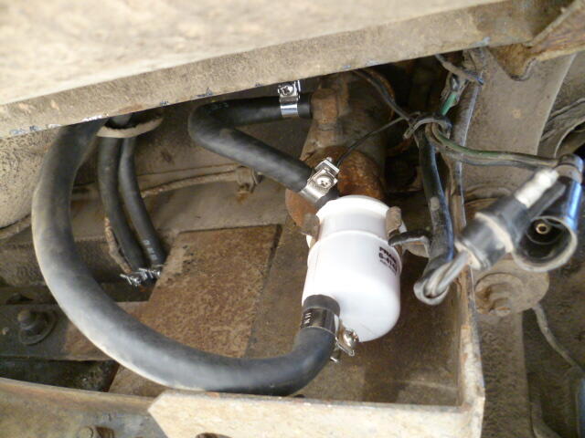
@HusseinHolland is working on the fuel pump primer. I'm just supporting cast.
-
Greg, I have only disassembled the later style rack (280), so I'm not positive about the function of that part you are trying to remove. But if it's like the 280 rack, that thing should either tap off or screw off the end of the rack. I would try to twist (in the "unscrew direction") and pull and see what happens. Was there a lock nut threaded onto the end which you already removed? And as for plcs... I reloaded them on page seven of this thread. Take a look here and see if this works for you: https://www.classiczcars.com/forums/topic/48621-steering-rack-disassembly-and-refurb/?page=7
-
Here's a crappy pic from a 74 260Z. Note that it's not the correct filter. Nipples aren't in the correct location, but it was what I could find at the time: Pic is a little too close-up to get a good handle of what's going on, but that's all I could find in my files. And also, I'm not even sure if the 260 is the same as your 73 240Z. But hope this might help some?
-
Excellent. With newer injectors so much easier to find than the old ones, it's great to figure out alternative!
-
Including the people who wrote the shop manuals?
-
How do you know?
-
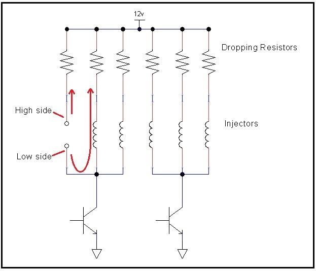
The AFR numbers look good. I'm no engine tuner, but I don't think 10-11 at WOT is that bad. Maybe a tad rich, but you usually want it rich at WOT, don't you? As for the resistance measurements, most of them look good. The two where you are sticking the probes into an empty injector socket (to measure back into the harness) really don't tell you much though. You're just reading a combination of ballast resistors and injector resistances in series parallel combination. Didn't hurt anything, but really no good data to be gleaned from that. If you're not sure what I mean... here's a pic that highlights the situation. You're just measuring a couple injectors and their dropping resistors in parallel, etc. In theory, if you're measuring back into the harness with the key off, you should read open circuit. But you would have to disconnect all the injectors (or at least the correct three) to see that. if you crank the meter up to the 2 MegOhm range. you might be able to pick up the leakage current through one of the output transistors in the ECU, but that's about it. So for the rest of the resistance measurements... You measured the ballast resistors at 5 Ohms and the injectors at 15.5 Ohms. Those measurements look great. Let me think about those numbers a little. In the end, if your AFR's are good, all that theory by the Volvo folks doesn't really matter. Might be applicable, might not. But your AFR's are on target, so who's to say there's a problem?
-
Yeah, I figured you were on top of that, but couldn't hurt to bring it up. And I hope you get your O-ring stuff worked out. Workmanship stuff is a real pet peeve of mine.
-
Cool. I think that would be interesting to compare against stock. Make sure you short your meter lead tips together and subtract that number from the injector resistance measurement. That shorted reading is lead resistance. For example... When I was measuring the injectors here today, I stuck both meter leads down into the injector connector and made connection to the blades in the JPT connector. I got 3.0 Ohms. Then trying not to move much, I shorted the tips of the leads together while also still connected to the JPT blades. I got 0.6 Ohms. In theory that 0.6 Ohms is lead resistance (plus crappy meter accuracy). Subtract the 0.6 from the 3.0 and I got 2.4 Ohms. The smaller the resistance you're trying to read, the more important it is to account for your lead resistance. Hoping this makes sense?
-
Page EF-56 of the 76 Manual says the dropping resistors should be 6 Ohms. I have not measured anything to verify. And I didn't find a spec for the injectors, but I measured a couple here and came up with about 2.4 Ohms. No accounting for the absolute accuracy (or inacuracy) of my meter, but that's what I got. Do you know the resistance of the high impedance injectors you are using?
-
I'm thinking that the higher the injector impedence is, the less impact the dropping resistors will have. What's the static resistance of the new injectors? In other words, if you put an Ohmeter across the new injectors and then do the same with the old, what are the resistances at DC? That dropping resistors would still be in series in the circuit with the "high impedence" injectors, but depending on the resistances, they may be overshadowed by the resistance of the injectors themselves. Voltage divider and all that. For example... If the dropping resistors are 1 Ohm and the injectors are 100 Ohm, it won't really matter whether they are included or not. That may be why you guys aren't seeing much of an impact whether the dropping resistors are installed or bypassed.