


Captain Obvious
Free Member
-
Joined
-
Last visited
Everything posted by Captain Obvious
-
 So much pressure to perform!!! Here's my steering rack thread. The original pics are dead because Photobucket sucks, but the important ones have been reloaded later on in the thread: https://www.classiczcars.com/forums/topic/48621-steering-rack-disassembly-and-refurb/ If there's any other pic missing that you want to see, let me know and I'll see if I can reload it.
 -
Glad to help. No, the TVS should be either "infinite" or "zero", so checking that on the 200 Ohm scale is the appropriate setting. Your HF meter probably reads between one and two Ohms on the 200 Ohm scale with the leads shorted together (mine reads 1.3 Ohms or so). So if you're checking the TVS (TPS), you should see pretty much that same reading when the switch is closed. WOT side closed at WOT. Idle side closed at idle. If the idle side isn't closing, it's probably either an adjustment issue, or someone has been in there messing with it.
-
Yeah, I'm not exactly sure why then needed that device in there at all in the first place. When the fuel vapor expands, you want it to push into the carbon can. It will do that with just a hose. When the fuel vapor contracts, you want to prevent a vacuum on the fuel tank, and there's already a check valve built into the filler cap that will prevent that. I haven't looked into it, but I'm unclear why they thought they needed that fancy unbalanced two way check valve at all. Maybe they wanted to run "a little bit" of positive pressure in the tank to help out the fuel pump?
-
Happy birthday to both of you! bartsscooterservice, You should send me one of those valve compressor tools for your birthday!
-
You have your Ohmmeter on the 200 Ohms range. That means the meter "pegs out" at 200 Ohms and any resistance reading higher than that reads as "1 ." There is probably nothing wrong with the air temp sensors you are looking at. You probably just have your meter on the wrong scale to get the proper reading. At room temperature, the air temp sensor should have a resistance of about 2200 Ohms. So if you try to read that on the 200 Ohm scale, it won't read. And even the next scale up (the 2K scale) is too low as well (since the resistance is greater than 2K Ohms). At room temperature, you'll probably need to go all the way up to the 20K Ohm scale to get a reading off the ATS. The resistance drops as the temperature increases, but the colder it is, the higher the resistance. Check it on a higher range on your meter and see what you get.
-
If you are getting the correct reactions on pins 91, 95, and 97, then the relay is working properly. I suspect the "failure" you are seeing on the test between 95 and 96 is a test procedure error. You're trying to measure resistance on a device while it's under power, and your meter is not interpreting the results as you would expect.* Out of curiosity... What resistance do you read between 95 and 96 if you swap the two meter leads? Put the meter on the 2K range, not the 2M range. * For those who care... The Ohmmeter works by applying a small known voltage across the device being tested and then measuring the amount of current that flows. If you try to measure the resistance of something that already has a voltage applied to it, the meter doesn't interpret the results correctly. And in this case, if pin 95 is connected to +12 and 96 is connected to ground, you're putting an Ohmmeter directly across a 12V power source. Meter will display incorrect results.
-
I really like the roadsters too. If I had all the room I needed for cars I wanted, I'd have one of those. I don't know anything about them specifically though, like... Are those the original door pulls? Very ornate! Look like something from a kitchen cabinet. Looks like you need a replacement brake master cylinder. The one you have now just doesn't match the rest of the car.
-
Well it sounds like progress and you certainly wouldn't be the first person to have multiple failures or things going wrong at the same time. I'm not a big fan of rebuilt components. Let's hope your second rebuilt alternator is the last of the issues!
-
That's what I figured. That spring can't be too strong as it has to be overcome by that small electromagnet. If the valve is frozen shut due to crusted fuel, you just might be able to manually open it to get some cleaner through it. But if it's a packed solid rusty mess inside, even being able to move that pintle tip probably won't save it.
-
Oh. That's fancy. I wasn't thinking hitting it with a hammer... I was picturing just pushing on the end with the plastic handle of a screwdriver. And if that didn't produce any interesting results, a requisite knock with the same said plastic handle. I figure if it takes much more than that, you'll never get it moving freely enough that the electromagnet would work.
-
Too... much... pressure....... You guys don't need me here. You got this! But just because I'm here, here's a couple other threads that talk about that check valve: https://www.classiczcars.com/forums/topic/60827-where-is-the-fuel-vapor-check-valve-located/?tab=comments#comment-558365 https://www.classiczcars.com/forums/topic/58221-starting-problem/?page=5&tab=comments#comment-528408 It's supposed to blow through in both directions (some check valve, huh). The trick is that it's supposed to blow through EASIER in one direction than the other:
-
I suspect the potential holes in the 280 door panel are for electric window and door lock switches that never happened.
-
At fifty cents apiece, it seems like it would be a worthwhile experiment to remove the original plastic pintle cap in order to be able to push on the tip of the valve and see if you can move it, or if it's stuck in place. Since this is a science experiment, right?
-
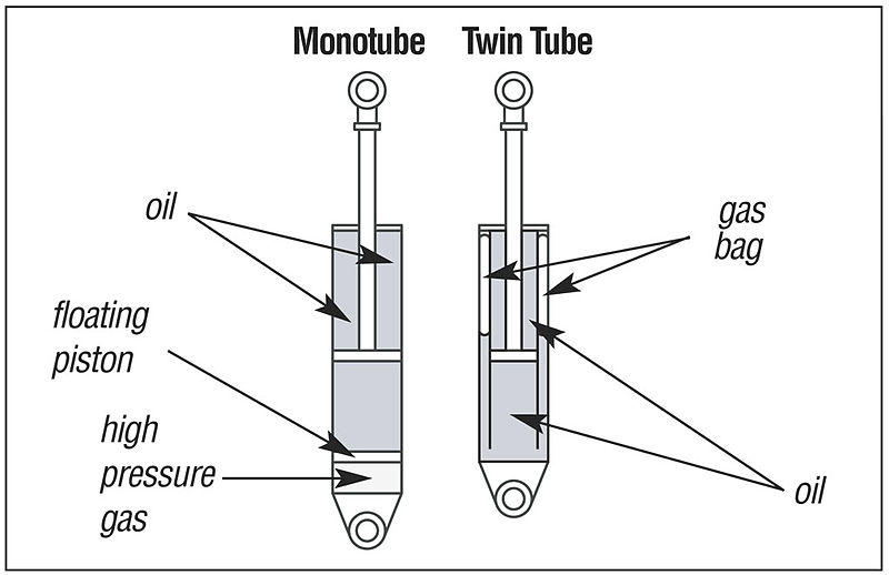
My pleasure. I'm just glad I didn't fall off my limb. One last thing while I'm here... I forgot to emphasize above that the gas in these struts is not intended to be a "lifting" device. It's simply in there to help inhibit foaming of the oil, not to provide any springiness. The fact that the shaft self extends due to the internal pressure is probably considered an unwanted side effect of the gas pressurization. I'm assuming (and KONI Lee would be the perfect expert to provide real insight) if they could get oil that never ever foamed ever, they wouldn't need to gas pressurize at all. Cheaper to manufacture and there wouldn't be all these people talking about how gas shocks raised their car's level. But the point is these aren't the old "air shocks" that you put on the back of your dad's station wagon back in the 70's and pumped up to get that really cool body rake. Everyone did that, didn't they?
-
-
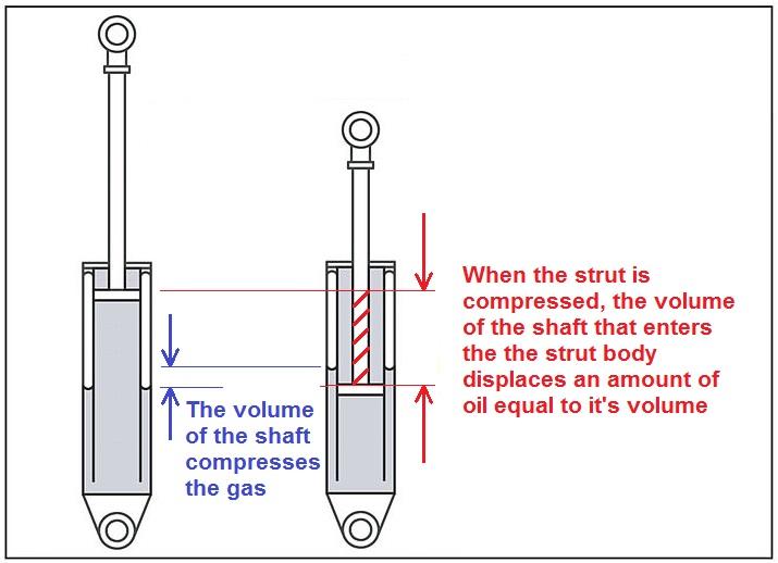
The plate you pointed to is the main hydraulic piston where the damper valve(s) are located. There is a seal around the outside of that plate and valves built into it. It does keep the bottom of the shaft centered, but that's not the only thing it does. That's where the primary "function" of the damper is located. Here's what I'm talking about with the gas compression. When fully extended, there will be some preload factory set pressure in the gas. And then when the strut is compressed, the gas does get compressed some, but it does not see compression proportional to the diameter of the main internal piston. It only sees compression proportional to the diameter of the shaft that enters the strut assembly:
-
-
-
In theory, the pistons only ever completely come to a stop exactly at TDC and BDC. However, in reality, it'll stop for the entire time you are taking up the bearing clearances. Hopefully that isn't very long...
-
I'm no suspension expert and I'm going to go out a little too far on my limb here, but I don't think that's quite right. I believe the force exerted by the gas is proportional to the diameter of the strut shaft where it exits the cartridge, not the diameter of the internal piston. I don't think the diameter of the internal piston has any effect in this case. My understanding goes like this: The more the strut is compressed, the more of the shaft is INSIDE the strut. The additional volume of the shaft (A*L) inside the strut assy will displace oil inside the body. That volume of oil displaced will compress the gas inside the strut, but only by the amount of VOLUME of the strut rod which has entered the strut. The internal gas pressure is static across the internal piston. At least that's how it appears to me way out on my limb here.
-
Well I'm glad that it turned out to be such a non-problem, but is it really OK for there to be that much play in the rack position inside the bushing? I thought the whole point that the bushing on the right left side of the rack is NOT round is to prevent exactly that kind of rotation? What's to prevent it from rotating back to where it was before? I guess I just never loosened mine up and collected all the tolerance in one direction...
-
-
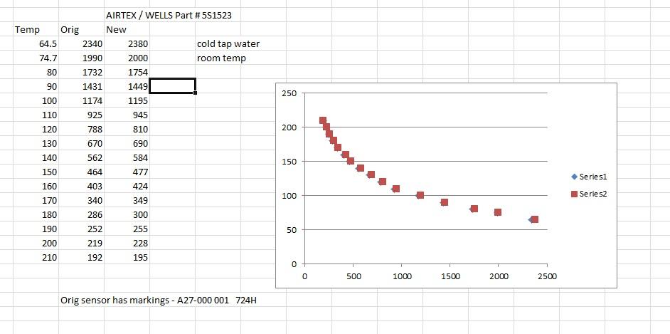
My original temp sensor was looking quite ragged around the edges, so when I adapted that 260 thermostat housing to my 280, I also took the opportunity to replace the temp sensor with a new one. I bought a new sensor off rock auto and to confirm that it had the same characteristics, I compared it to my original on the stove in a pot of water. I just wanted to be sure. They were slightly different, but well within the accuracy limits laid out in the FSM. Here's my "test rig": And here's a summary of the results:

-
-
The middle line is the "typical" (perfect) measurement. and the outside lines are range "limits". So if you are designing a system, you should probably aim for typical (halfway between max and min), but since any sensor you might purchase could be anywhere between those two points, you have to either characterize the sensor and trim the system for that sensor, or your system needs to be able to work acceptably with any sensor within that range. Those sensors are RTD's and they are available with different curves. And looking at the data for that GM sensor, it looks like it's a different curve. Doesn't the EFI system you are putting in place already expect a specific certain sensor curve? Is there any info in the documentation about what it's expecting? And lastly, here's a chart I put together for the 280 coolant temp sensor. I didn't look into it, but I would assume the ZX is the same?


