Captain Obvious
Free Member
-
Joined
-
Last visited
Everything posted by Captain Obvious
-
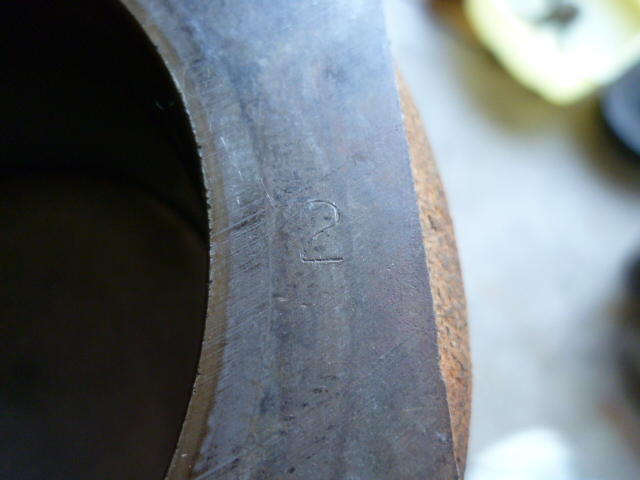
 Haha! I've got calibrated eyeballs. That, and it's easier to spot it when you know what you're looking for. The 82 cam gear looks stock to me. Looks just like the three ZX pulley's I've messed with in recent past. They went to the eight hole version some time between 77 and 81. They also changed if from a sand casting to an investment casting (not that anyone really needs to know that), which accounts for the change in surface texture. Now, as for your 77 cam gear, I'm not sure. My 77 gear has four holes, so it's different than yours. But dies wear out, so it's completely conceivable that yours is stock, just from a previous die revision. They're always trying to cut weight, waste, and cost. Some (most?) of the aftermarket gears don't have the little timing mark gash on the rear. So by virtue that it's got the timing gash, I'd vote for stock. My non-expert tips on pulling the pistons out... Pistons come out the top (just sayin'). And make sure you carb cleaner the carbon ring at the tops of the cylinders completely clean first. Don't want to push the rings over that hump. Don't use anything abrasive on the cylinder walls (don't use sandpaper to remove the carbon ring). Push the pistons out slow and evenly. I have seen a few very rare occasions where a piston ring will break when it snaps out of the bore. So if that happens, don't freak. Did you find the block numbers? Here's a pic of one of my ZX pistons and the corresponding stamp on the block. Piston: And the stamp on the block. Left side right next to each cylinder bore. All my pistons were #2 and all my block stamps were 2 as well:
-
So my ZX motor came out of a car with an auto trans, and I've got a couple questions about that... First, I've noticed that the thin steel plate that goes between the block and the transmission is different. The manual version is one piece, but the auto version uses a two piece version with a separate small piece that bolts into place on the bottom. They did that so you could access the bolts that attach the torque convertor to the flex plate. Question is... Can I use the auto version with a manual transmission, or do I need to source one of those plates? Second, Are flywheel bolts the same as flex plate bolts? I'm guessing that the flywheel is probably thicker than the flex plate and used longer bolts, but I'm sure someone here has been through all of this before and knows off the top of their head.
-
Non-unretouched photograph:
-
I did guarantee it! Hope it's not too bad. I've got a soft spot for the early 260s. (And as you've found... The early 260's have soft spots).
-
Haha!! Fair enough. Hope it comes together!
-
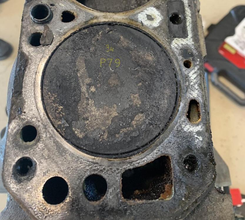
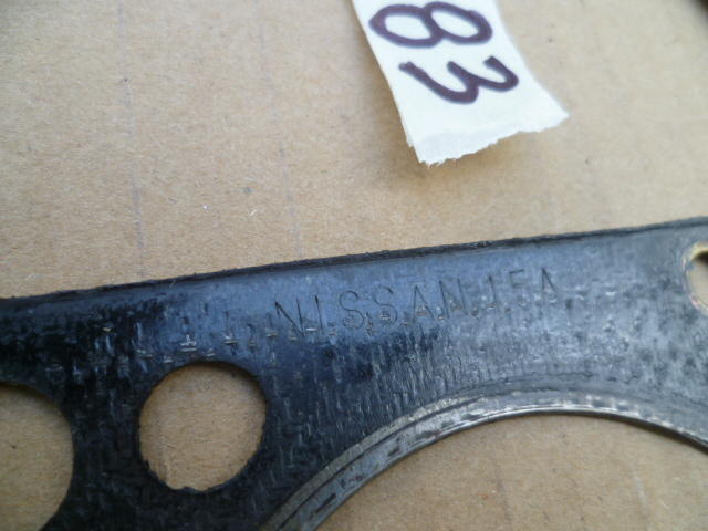
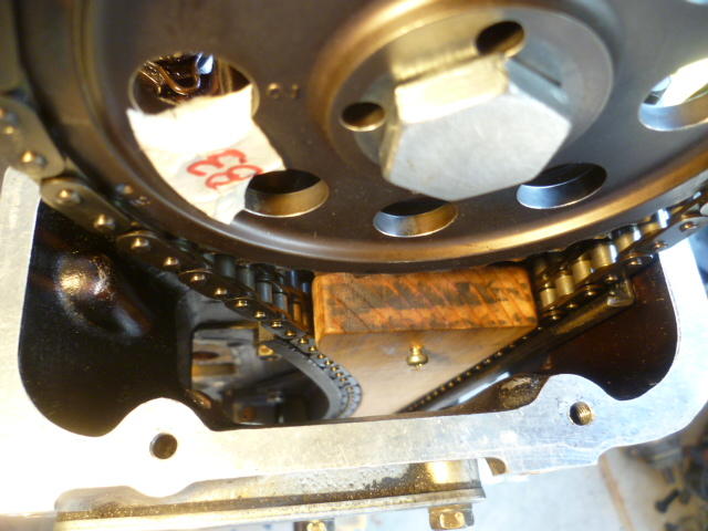
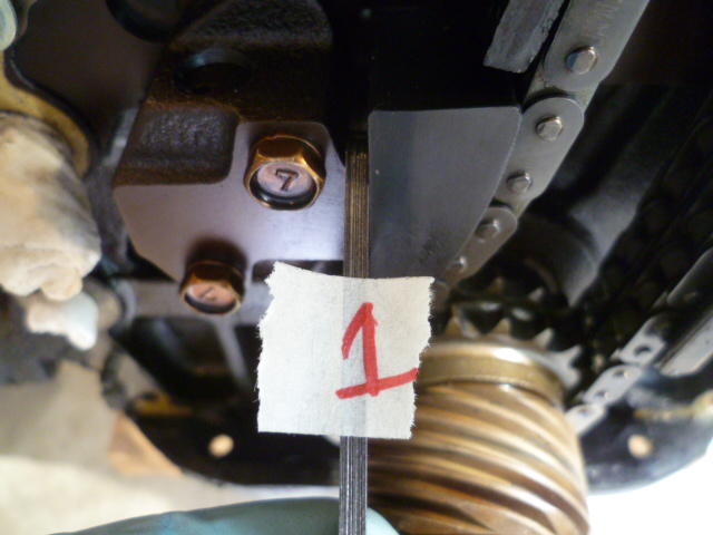
Cool! Standard size stock pistons! I can make out the P79 on piston #6, along with the 34 marking (large "3" and smaller "4") to indicate stock bin sizing. I'm assuming that if #6 is stock, then the rest of them are as well. There should be a "3" stamped into the top surface of the block next to that piston. I can't make that out because it's hidden under head gasket residue. Clean all the pistons up and clean off the block deck and you should be able to see all the numbers. Nothing else really catches my eye, Looks like a completely appropriate amount of carbon for a used ZX motor. Should clean up well. I'll measure the thickness of my head and you can do that same. I'm fairly confident that mine has never been shaved, so you can use that number to check yours too. I've looked at four head gaskets recently from different origins, and all four had manufacturing markings in the same spot... The rib between piston #1 and the timing chain cavity. Like this: Take a look at yours and see if you can find any marks. If it's aftermarket, it'll tell you that someone had been in there before.
-
LOL. Well if you ask me, the problem isn't the balance tube. The problem is that you removed the flat tops. Good luck with the project. Too bad you won't get to enjoy it much this season.
-
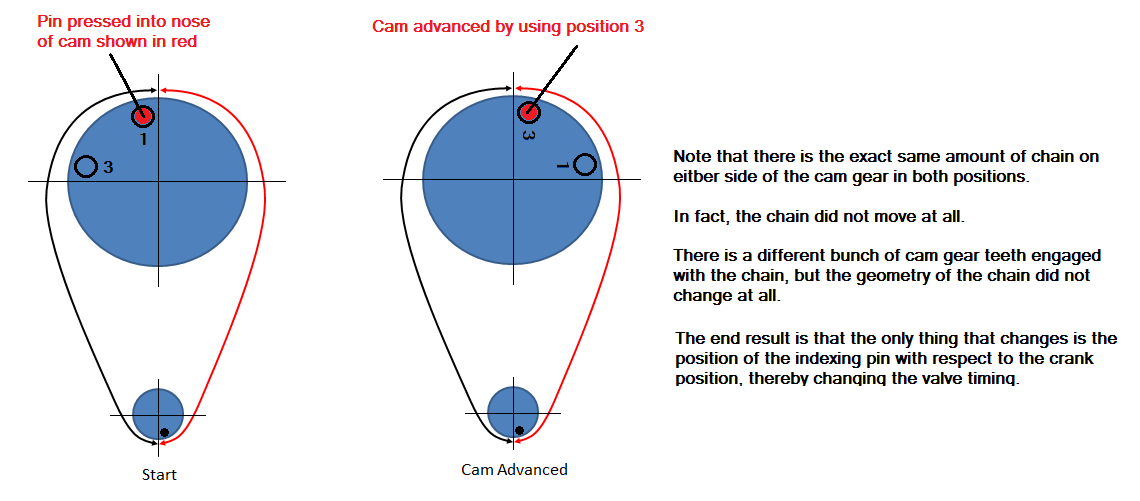
Here's the rub. You asked about a moved link... The point is there was no moved link. You moved the sprocket, not the link. All the links stayed in the exact same location. All the links that were on the tight side before the sprocket change are still on the tight side All the links that were on the loose side before the sprocket change are still on the loose side. You did not move any links. You carefully took off the sprocket without disturbing the chain position, rotated the sprocket one link clockwise (without disturbing the chain position), and then put the sprocket back on (without disturbing the chain position). The links never moved. At all. Ever. After the move, there will be 41 links between the default dots rather than 42 links*. But not because you moved a link. It's because you moved the sprocket. * Note that I have never counted them to verify that number. I'm counting on you for the accuracy of that.
-
LOL!!!
-
There were originally three paths for water to go through the flat top carb system. 1) First was through the carb bodies themselves. Those have already been removed since you are now running round top carbs. 2) The second path is through the intake manifolds. Inlet you have labeled #1 and outlet labeled #2. Since they are disconnected from any water source, you can plug them, remove them and plug the resultant holes, or simply leave hang open. 3) The third path for coolant is routed through the balance tube. Inlet comes up from underneath the two carbs about in the middle. It's the flare style nipple at the bottom of this pic: and the outlet is what you have labeled #3. That outlet pipe #3 is rotated 180 degrees from where it's supposed to go. It's supposed to go around the back of the head and tie back into the water pump inlet. The other thing in the pic above (#5) is your original idle speed control. Again, since you have switched to round top carbs, that thing doesn't do anything anymore (assuming you have it tightened down completely). You can plug, remove and plug or leave it as is.
-
-
Nice!! How's it feel on the road?
-
Oy. That hurt. If that were mine, I wouldn't be in any rush to paint it that color. There.... We're even.
-
All that, and those guns are questionable about aim and area of the target. And there's also emissivity concerns. Good for ballpark, but I wouldn't lend too much credibility to the numbers.
-
Oh, and did you check the wipe pattern on the followers, or since you shimmed stuff the same amount as the head shave, are you assuming it's the same as it was originally?
-
What Zedheadsaid with one exception. I'd do the quick oil change after 100 miles like you mentioned. My thinking on that is that there may be debris knocked loose by all the work you did to the engine that you want to get out of there. Hopefully if something was knocked loose, it'll be in the filter. I'm guessing you were thinking the same thing. And if you're going to do that, I'd try to get the nose of the car up a little bit to make it downhill for more oil to run out the drain hole in the pan. And I'd get it nice and hot first so the oil is all mixed up and runny from the heat. Park it and immediately try to get it draining. Just don't burn yourself on the exhaust pipe or scald yourself with the hot oil. Just let the drain plug fall into the pan and you can fish it out later. My wounds have just recently healed over.
-
Awesome! Looks great so far. One broken bolt on an manifold heat shield? You're ahead of the game! Crack the front main pulley bolt loose before you take the head off. The friction from the valve train will help hold the crank while you loosen the big bolt. And also you won't run the risk of bunching up the chain in a tangle and wedging something. You'll probably need an impact wrench. Do you have one of those? And then when you go to pull the head, remember the special procedure for loosening the head bolts. And don't break any of them!
-
One last try... I see your pic and raise you one:

-
Yeah, I'm gonna try just one very last time and then give up....
-
And no zip ties were harmed during this procedure.
-
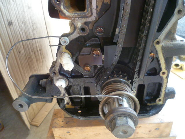
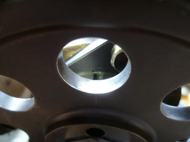
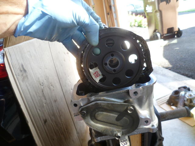
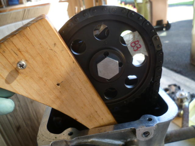
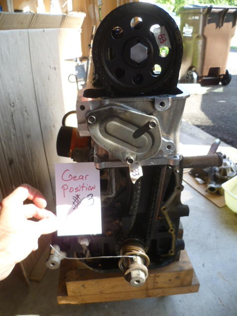
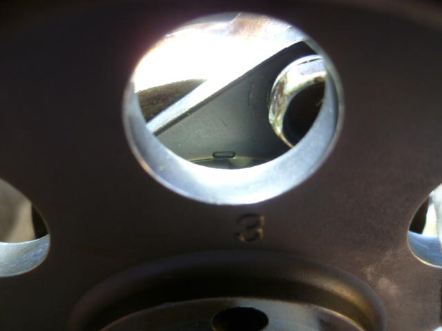
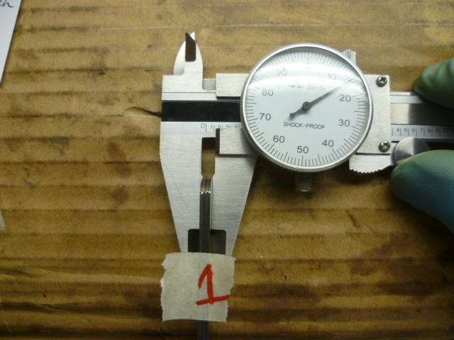
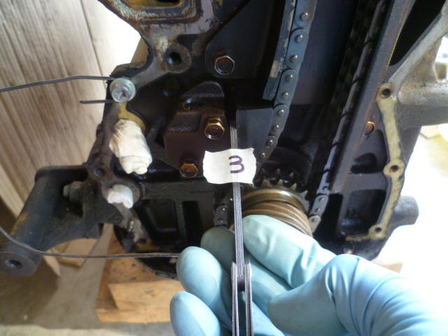
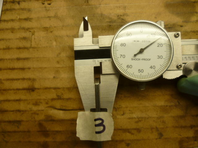
I'm not confused at all, and the proof is in the pics. System with cam gear in position 1: I rigged up a little wire pointer to indicate TDC. Doesn't have to be exactly dead nuts on TDC as long as it's the same spot each time: Here's the timing marks in position 1: Then I used my chain wedge tool (just like if I were doing this in the car). Tool wedged down into place: Take the cam gear off: Move the gear to position 3 and take out the wedge tool: Here's the system in position 3: Here's the timing marks in position 3. The valve timing has become advanced compared to position 1. Exactly as one would expect: Now... For the chain tension. I used a feeler gauge to measure how far out the adjuster is. This is position 1: Measuring the feeler gauge, the tensioner is out about .115 with cam gear in position 1: Repeating the measurements for position 3: End result? The adjuster protrudes the same amount regardless of the cam gear position:

-
Rut roh! Well as I said, I've not proven my calculations to be correct, but with a .049 (1.244mm) thick head gasket and .005 off the block I get 11.54:1 I get 502.45 cc uncompressed volume and 43,55 cc compressed for a result of 11.54. Remember, I'm just a guy with a spreadsheet. You got any airports near you? LOL!!
-
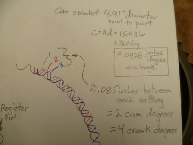
Nope. What he said. It's four (crank) degrees per position change:
-
I disagree completely. I do not believe it depends on the perspective of the viewer. I say that the tension on the chain is independent on which cam index hole 1-3 is used. Would you believe me if I took some pics? I'll put the gear in position 1 and take a pic of the tensioner. Then I'll move the gear to position 3 and take another pic of the tensioner. My belief is that the tensioner will look identical in both those pics. I say the plunger will be the same distance out regardless of what hole the cam gear is in.. If I show you, would you believe it then? What say ye? Haha!! @240260280 I challenge thee to a geek-off.
-
Awesome! What kind of gas are you going to use with that CR? And BTW, when I run the CR on your combo, I get a slightly higher number than you do. I get 11.42:1, but I've not reached the point where I'm completely confident in my numbers, What number are you using for head gasket thickness after it's been crushed into place? I get 11.42:1 with a .120 thick head gasket on an F54 and a 39cc chamber.