


Captain Obvious
Free Member
-
Joined
-
Last visited
Everything posted by Captain Obvious
-
 Dave, I haven't looked at the design of the ignition modules to see if they reference either side to chassis ground. My assumption is that neither side would be tied to hard to ground in the module. That assumption is based on the twisted-pair nature if the pickup wiring. They are trying to reduce the loop area with the twisted pair and it would completely defeat that purpose if they would tie one side to ground in multiple locations. My assumption without any reverse engineering is that the pickup inputs are not galvanically isolated (with a transformer or something), but they may feed some sort of floating input differential amp at the input stage of the module. If that's the case, tying one side to ground might not cause it to malfunction, but it certainly isn't necessary or desired.
 -
Nice work. Some input below: There is play in the spindle bearings, there is play in the feed leadscrews, and once you start putting forces on stuff, everything bends and flexes and squirms. Even steel. That's why it's all really "made of rubber". You're pushing a hardened bearing shell with rounded corners into a hole. The rest of the system will squirm around to make it fit when you start putting pressure on it. Best thing you could do would be to use the co-ax to indicate the center of the original hole and then lock down both the X and Y travel leadscrews (I'm assuming you have gib lock screws on those?) before you start the boring operation. And I know you can't do this because of the set-up, but the less you have the spindle sticking out below the head, the better. The more it sticks out, the flimsier it gets. About that 4mm distance measurement of the wall thickness... That's not what's really important. What you really care about is that the center-line of the two shafts are in the right locations. I know you're interpolating that using the resultant wall thickness, but of course it would be better to measure the centers of the holes. Also, of course, if you get the new hole in the exact same center as the original smaller hole, you don't even have to measure it. You'll be spot on.
-
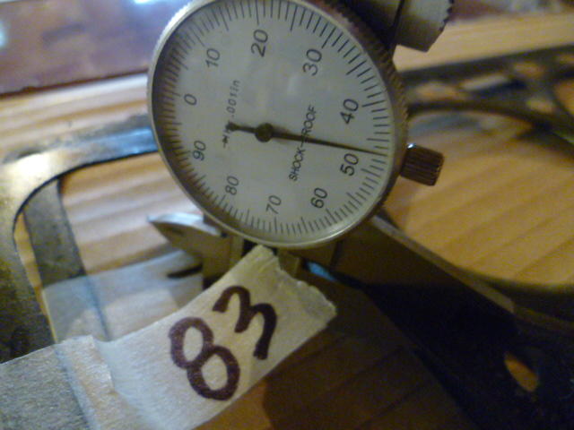
About a thousandth total runout? Kinda hard to tell because the indicator is buzzing around at such a high spindle speed. Usually when I'm doing something like that I disconnect the spindle drive completely and just rotate it by hand to find the high and low spots. Might be nice to know where the high and low are. Would help you determine if the runout is in the tool, the spindle, or just random mounting variation. You work with what you got, but MT3 aren't known to be the most accurate tool in the drawer.
-
I got an 83 2+2 parts car for sale cheap. I know this isn't the classified forum, but thought I would throw that out there.
Nice. You sure do have a long chang! Do you have any fly cutters. Seems your diameter adjustment could be made a littler easier, and no welding required. Usually used for facing a flat surface (like a head mating surface), but with the right cutter grind and geometry, I don't see any reason you couldn't use one to bore your hole:
Glad to help. Hope the project goes smooth.
And... The smaller red and black wires leading deeper into the tach are what makes the gauge needle move. I can tell you more about that if there are problems, but I'm hoping it just works and we don't have to.
Red is +12. Black is ground. Green is speed input.* White is gauge illumination lamps. *Note that I don't know what kind of signal the tach is expecting, but the green wire is where it should occur.
From those pics, I believe the black wire is ground side for power. Can you take the brass hex standoffs off and get a shot of the back side of the board? Is there enough slack in the tether wires connecting the board to the mechanical portion to spin the board over and get a straight on shot?
Maybe. Can you post a pic of the other side of that tach board? I can probably tell you which ones are power and ground.
Agreed. Repair looks fully functional. Might want to use something to pot that wire into place so you don't bump it or catch it on something and pull more of the PCB trace off the board. Hot glue as mentioned above, or an epoxy blob or two.
The flat top pistons for the F54/P79 system stick up a half millimeter (,020 in) out of the block above the deck. I measured the thickness of a used factory gasket for that combo to be about 1.2 mm (.047 in), I don't know if the earlier years head gaskets are thicker, but for the later years, it seemed to work fine.
 For failures like that, typical SOP where I come from is to solder jumper wires over the damaged section (like the PO did), but do it with a little higher quality workmanship. That board looks simple enough that you could probably daisy-chain point-to-point wire the whole thing. Do you have a need to lay down new copper where the damaged trace is, or you just want something that works?
As I mentioned before, based on how clean everything is on the valve train, someone has been in there, and very recently. Way more recently than even 30K miles ago. Today's oils aren't going to keep things that clean, and certainly not 1978's oils. I'm thinking someone had the head off right before your bought the car? That thing is cleaner on the inside than it is on the outside! So what are the paint marks on the cam? Is that a "7" I can see in the one pic? And paint stripes on the tops of all the followers?
I know, and I agree completely. I was just making a joke about the nickname your mechanic coined said some time ago.
And the guy who made preparations A through G. They were complete failures.
Woof. Still considering yourself "lucky"? So you're thinking oil getting pulled up past the rings and then getting sucked out the intake valves into the plenum?
Looking at the cleanliness of that valve train, it's clear someone has been in there not many miles ago. How far are you from Flemington?
So this welded cutter you talked about... You're not using a boring bar in a boring head? In your close-up pic, that's what it looks like. But surely you're not thinking of welding the bar INTO the boring head, are you? I was being sarcastic above, but now that you brought it up again, I'm wondering if you're serious, or I'm simply confused as to what your cutter consists of. So you got a mill-drill. We're not judging. I was going to ask before, but thought you had set-up worked out... Can you mount the bell housing trans side up so the hole you want to bore is closer to the head? Or is the bell then too large to get enough clamps on it to lock it to the table? If you can mount it that way, you'd have no problems with Z travel length. They call that "piloted" as in you're using a "piloted cutter". Not uncommon, and a good way to achieve higher accuracy, especially in flexible set-ups.
Yup. That's what I meant with a standard indicator. Doesn't have to be the fancy co-ax. The co-ax just keeps the reading dial facing forward and makes it easier. Not required, but easier. I use my very old Starrett "Last Word" most of the time. Chuck the tail up in the spindle and take her for a spin:
For failures like that, typical SOP where I come from is to solder jumper wires over the damaged section (like the PO did), but do it with a little higher quality workmanship. That board looks simple enough that you could probably daisy-chain point-to-point wire the whole thing. Do you have a need to lay down new copper where the damaged trace is, or you just want something that works?
As I mentioned before, based on how clean everything is on the valve train, someone has been in there, and very recently. Way more recently than even 30K miles ago. Today's oils aren't going to keep things that clean, and certainly not 1978's oils. I'm thinking someone had the head off right before your bought the car? That thing is cleaner on the inside than it is on the outside! So what are the paint marks on the cam? Is that a "7" I can see in the one pic? And paint stripes on the tops of all the followers?
I know, and I agree completely. I was just making a joke about the nickname your mechanic coined said some time ago.
And the guy who made preparations A through G. They were complete failures.
Woof. Still considering yourself "lucky"? So you're thinking oil getting pulled up past the rings and then getting sucked out the intake valves into the plenum?
Looking at the cleanliness of that valve train, it's clear someone has been in there not many miles ago. How far are you from Flemington?
So this welded cutter you talked about... You're not using a boring bar in a boring head? In your close-up pic, that's what it looks like. But surely you're not thinking of welding the bar INTO the boring head, are you? I was being sarcastic above, but now that you brought it up again, I'm wondering if you're serious, or I'm simply confused as to what your cutter consists of. So you got a mill-drill. We're not judging. I was going to ask before, but thought you had set-up worked out... Can you mount the bell housing trans side up so the hole you want to bore is closer to the head? Or is the bell then too large to get enough clamps on it to lock it to the table? If you can mount it that way, you'd have no problems with Z travel length. They call that "piloted" as in you're using a "piloted cutter". Not uncommon, and a good way to achieve higher accuracy, especially in flexible set-ups.
Yup. That's what I meant with a standard indicator. Doesn't have to be the fancy co-ax. The co-ax just keeps the reading dial facing forward and makes it easier. Not required, but easier. I use my very old Starrett "Last Word" most of the time. Chuck the tail up in the spindle and take her for a spin: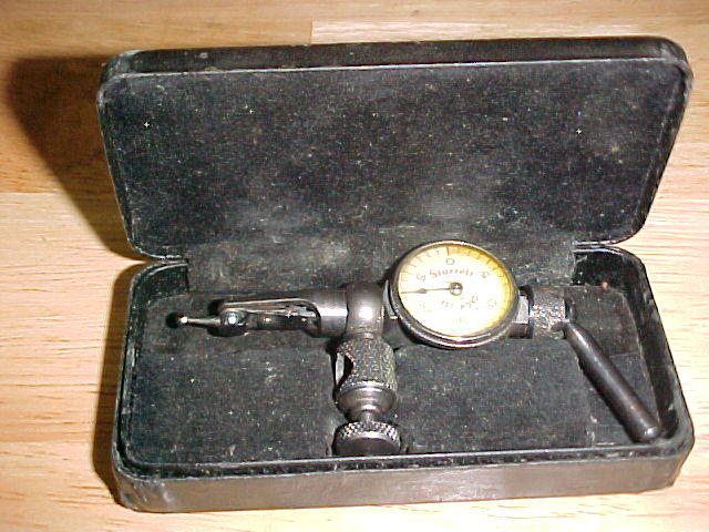 Pretty sure you know this already, but it'll be more accurate if you don't try to do it all in one pass. Flex and all. I would consider a hundred thousandths cut relatively aggressive. And if you're looking for a great cutting oil for aluminum... WD-40. And your spot weld idea is fantastic. I've got a cabinet of boring heads with the bars welded in for specific diameters. Said no machinist ever.
LOL. It's a calling. And for the record... I've never done anything like that. Ever. For sure. Never. Especially when threading. Where's the growing nose emoticon?
Nice! The tooling store works fast for you! I'm guessing you already had the boring head, but just kinda forgot about it? MT3 spindle on the mill? Make sure you have the cutter in the right way... The way you have it now your gonna have to run in reverse. You have a back-gear on the mill? And the co-ax indicator isn't a top priority piece of tooling, but it sure is nice when you get to use it. You could just mount a traditional indicator in a collet in the spindle and spin that. The co-ax indicators are nice because you can keep the dial facing forward and don't need to peek around back to get the reading when the spindle is halfway around or at 270 degrees.
I know you know this already, but you always need more tooling. Always.
Pretty sure you know this already, but it'll be more accurate if you don't try to do it all in one pass. Flex and all. I would consider a hundred thousandths cut relatively aggressive. And if you're looking for a great cutting oil for aluminum... WD-40. And your spot weld idea is fantastic. I've got a cabinet of boring heads with the bars welded in for specific diameters. Said no machinist ever.
LOL. It's a calling. And for the record... I've never done anything like that. Ever. For sure. Never. Especially when threading. Where's the growing nose emoticon?
Nice! The tooling store works fast for you! I'm guessing you already had the boring head, but just kinda forgot about it? MT3 spindle on the mill? Make sure you have the cutter in the right way... The way you have it now your gonna have to run in reverse. You have a back-gear on the mill? And the co-ax indicator isn't a top priority piece of tooling, but it sure is nice when you get to use it. You could just mount a traditional indicator in a collet in the spindle and spin that. The co-ax indicators are nice because you can keep the dial facing forward and don't need to peek around back to get the reading when the spindle is halfway around or at 270 degrees.
I know you know this already, but you always need more tooling. Always.


Important Information
By using this site, you agree to our Privacy Policy and Guidelines. We have placed cookies on your device to help make this website better. You can adjust your cookie settings, otherwise we'll assume you're okay to continue.