


Captain Obvious
Free Member
-
Joined
-
Last visited
Everything posted by Captain Obvious
-
 LOL. I suspect you're not far behind me! Haha!! OK, OK... I'm gonna take a stab and say that @Dave WM was involved? Maybe?
I just took a quick look at the parts breakdown and they call that front gear the "Main Drive Gear, and it's mate is "The Counter Drive Gear". 6 GEAR-MAIN DRIVE GEAR-COUNTER DRIVE The do, however, number the remaining gears: 19 ASSY-GEAR,1ST MAIN S 20 ASSY-GEAR,2ND MAIN S 22 ASSY-GEAR,3RD MAIN S I probably should have checked first.
I don't believe I'm misconceived or confused. I've not been inside a Z tranny, but your description of operation is exactly how other transmissions I have been inside have worked. I guess my only confusion is why are you calling it a 4th gear pair? Does Nissan refer to that main front driving gear as the "4th gear"? And my point is that there is no 4th gear pair because when you're in 4th no power is being put through any gears when you're in 4th gear. In fact, you could grind all the teeth off that front gear completely and 4th gear would still work. It doesn't need a pair. it's just semantics really. You clearly know exactly what's going on inside. I'm just protesting the implication of the naming convention I guess.
I didn't pay complete attention (because it wasn't my horse in the race), but I remember someone sent injectors out for cleaning and then when they came back, they didn't use them for a "while". And after sitting, some of them didn't work right? Something like that? Theory being that they rusted up inside over the delay time. I don't remember if that was on this forum, or someplace else. May not have even been a Z. But I remember something about that.
Yeah, that's a nice plug. Way nicer than using a normal bolt. The shoulder provides a much better sealing surface (as it was intended). So, is the head metric? Or is it (like so much of the other "metric" stuff available here) metric threads, but an English sized head (like 1/2 inch)? Also, I wouldn't use the O-ring. I'd use an aluminum or brass crush washer designed for that. I don't think the O-ring is the right seal for that type or twisting/crushed sealing application. That O-ring was probably designed for an application that had a counterbore cut in the female portion as a groove to hold the O-ring. It's nice that it came with, but I wouldn't use it.
If you're going to order some stickers from a pro, PM me first. We might be able to work out a split cost.
I like those plugs. Are they flat bottoms? Like made to be used with a crush washer seal of some sort?
I've got one listing sheet that I "found on the internet" somewhere, but I don't like the numbers. Doesn't look right to me so I'm reluctant to even post it. Got a question though while I'm here... You said you want to know the "4th gear tooth counts". My understanding is that 4th gear doesn't HAVE a count. I've never been inside a Z tranny, but with the others I've been inside, it would be straight through with the input shaft locked to the output shaft. All the counter gears just coasting along for the ride. None of the intermediate gear counts matter at all. Is the Z tranny not like that in 4th?
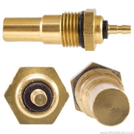
And although nobody asked (rarely stops me), here's some additional info about those sensors. The original sensors are actually two pieces. A steel threaded portion and a brass sensor portion. The steel part uses a straight thread and the reason they can get away with a straight thread (not tapered) is because that's not what holds back the coolant liquid. The liquid sealing surface actually has nothing to do with the threads. The liquid is sealed by the small beveled edge further down the sensor. Taking liberties with Granny's photo: Some of the newer aftermarket sensors are all one piece brass like the below. Note that the O-ring does not hold back the coolant. All it does is keeps dirt and junk out of the threads. The same beveled surface is what keeps the coolant in:
LOL. I suspect you're not far behind me! Haha!! OK, OK... I'm gonna take a stab and say that @Dave WM was involved? Maybe?
I just took a quick look at the parts breakdown and they call that front gear the "Main Drive Gear, and it's mate is "The Counter Drive Gear". 6 GEAR-MAIN DRIVE GEAR-COUNTER DRIVE The do, however, number the remaining gears: 19 ASSY-GEAR,1ST MAIN S 20 ASSY-GEAR,2ND MAIN S 22 ASSY-GEAR,3RD MAIN S I probably should have checked first.
I don't believe I'm misconceived or confused. I've not been inside a Z tranny, but your description of operation is exactly how other transmissions I have been inside have worked. I guess my only confusion is why are you calling it a 4th gear pair? Does Nissan refer to that main front driving gear as the "4th gear"? And my point is that there is no 4th gear pair because when you're in 4th no power is being put through any gears when you're in 4th gear. In fact, you could grind all the teeth off that front gear completely and 4th gear would still work. It doesn't need a pair. it's just semantics really. You clearly know exactly what's going on inside. I'm just protesting the implication of the naming convention I guess.
I didn't pay complete attention (because it wasn't my horse in the race), but I remember someone sent injectors out for cleaning and then when they came back, they didn't use them for a "while". And after sitting, some of them didn't work right? Something like that? Theory being that they rusted up inside over the delay time. I don't remember if that was on this forum, or someplace else. May not have even been a Z. But I remember something about that.
Yeah, that's a nice plug. Way nicer than using a normal bolt. The shoulder provides a much better sealing surface (as it was intended). So, is the head metric? Or is it (like so much of the other "metric" stuff available here) metric threads, but an English sized head (like 1/2 inch)? Also, I wouldn't use the O-ring. I'd use an aluminum or brass crush washer designed for that. I don't think the O-ring is the right seal for that type or twisting/crushed sealing application. That O-ring was probably designed for an application that had a counterbore cut in the female portion as a groove to hold the O-ring. It's nice that it came with, but I wouldn't use it.
If you're going to order some stickers from a pro, PM me first. We might be able to work out a split cost.
I like those plugs. Are they flat bottoms? Like made to be used with a crush washer seal of some sort?
I've got one listing sheet that I "found on the internet" somewhere, but I don't like the numbers. Doesn't look right to me so I'm reluctant to even post it. Got a question though while I'm here... You said you want to know the "4th gear tooth counts". My understanding is that 4th gear doesn't HAVE a count. I've never been inside a Z tranny, but with the others I've been inside, it would be straight through with the input shaft locked to the output shaft. All the counter gears just coasting along for the ride. None of the intermediate gear counts matter at all. Is the Z tranny not like that in 4th?
And although nobody asked (rarely stops me), here's some additional info about those sensors. The original sensors are actually two pieces. A steel threaded portion and a brass sensor portion. The steel part uses a straight thread and the reason they can get away with a straight thread (not tapered) is because that's not what holds back the coolant liquid. The liquid sealing surface actually has nothing to do with the threads. The liquid is sealed by the small beveled edge further down the sensor. Taking liberties with Granny's photo: Some of the newer aftermarket sensors are all one piece brass like the below. Note that the O-ring does not hold back the coolant. All it does is keeps dirt and junk out of the threads. The same beveled surface is what keeps the coolant in: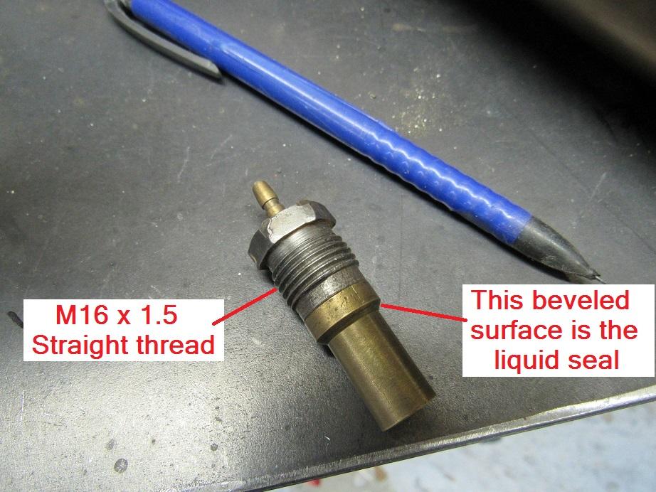
 Gotcha. So the traditional options are silk screening and pad printing. I know very little about either one and have never done either personally. Have you investigated someone who's business is to make stick-on labels? This should be a simple one for them.
I've never been inside a Z transmission, let alone an early one. But just because it's been 19 hours and there's been no action... So what is it I'm looking at here? Is that the 5-R section of the trans, or is that an unsynchronized first gear? (Did they use an unsynchronized 1st gear version on the trucks of the same era?)
Actually it wasn't that glamorous. It was actually black printing on a white background, but was done in reverse so the lettering was the (white) unprinted portion. If I were doing this, I would change the design so that the lettering is recessed into the fuse block cover. Then when the printing was done, I would slather the whole top surface of the cover up with a thick white paint, making sure it got down into the recessed lettering "divots". Then I would sand the whole face carefully on a flat surface with some fine grit sandpaper. That would do two things. 1) Take the paint off everywhere except the recessed lettering, and 2) take the printing lines off the top surface of the cover and make it look better because it's smoother. Only problem is... It's a different cover printing for each different year.
I suspect the only thing they would be good for is the core return on a new battery. Lead-acid batteries don't like to be taken down completely dead and usually suffer permanent damage. Probably shorted cells internally.
How about something like this? https://www.amazon.com/Mayhew-Pro-37019-Seal-Puller/dp/B008M238HU?ref_=ast_bbp_dp I've got something similar from HF, but I can't find it on their website.
Nice. I was sure you could come up with something! I've got some small suggestions to make it better now that proof of concept has been successful, but none of that matters until you decide to make the next one. Good work! I'm happy that this is one of those "difficult Datsun jobs" that I've never had to deal with!
Gotcha. Shows what I know! LOL. So all you need for a proof of concept test is a citric acid based thixotropic paste. I suspect the finer the sawdust, the better, and (again, for proof of concept), don't know if you need to spring for xanthan gum. That stuff is a lot more expensive than corn starch (which you already have). Cooked corn starch slurry (cooked to activate the corn starch), with citric acid added. Only thing I'm not sure about is the reaction between the starch and the acid. I spend a fair amount of time in the kitchen, but I'm a little rusty* on which thickening agent to use in which application and I'm not sure if there will be compatibility issues. I do remember there are some restrictions on which starch to use when preparing a citrus fruit based dessert, so I'm assuming those restrictions would apply here. Could maybe use plain ol' gelatin as a thickener if corn starch isn't compatible? Maybe put in a little propylene or ethylene glycol to slow down evaporation? *See what I did there?
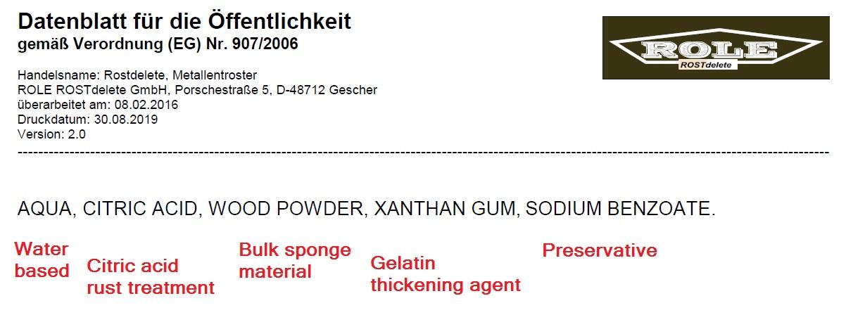
Honestly I'm not sure any garage chemistry is even warranted. My read on the whole thing is all that stuff is (is) a rust converting acid suspended in a bulky spongy gelatinous base material that slows down evaporation. The preservative is necessary because the citric acid will harbor critters over time and "spoil" (probably smell bad and lose effectiveness). But the point is.... It's a rust converting acid in a gelatinous bulk material to slow evaporation. I believe there are lots and lots and lots of phosphoric acid based materials on the market available at this side of the globe. My (own untested) suspicion is that I bet the phosphoric based stuff would work better, but is less safe to use and potentially worse for the environment. I suspect the citric acid based stuff is uber-safe and all that. From the list of ingredients, it looks like you could eat it. But that doesn't mean it works better, and in fact, most times the worse something is for you and the environment, the better it works. Is there some reason people would believe that citric acid based compound would be more effective?
From their website (with my additions in red):
Gotcha. So the traditional options are silk screening and pad printing. I know very little about either one and have never done either personally. Have you investigated someone who's business is to make stick-on labels? This should be a simple one for them.
I've never been inside a Z transmission, let alone an early one. But just because it's been 19 hours and there's been no action... So what is it I'm looking at here? Is that the 5-R section of the trans, or is that an unsynchronized first gear? (Did they use an unsynchronized 1st gear version on the trucks of the same era?)
Actually it wasn't that glamorous. It was actually black printing on a white background, but was done in reverse so the lettering was the (white) unprinted portion. If I were doing this, I would change the design so that the lettering is recessed into the fuse block cover. Then when the printing was done, I would slather the whole top surface of the cover up with a thick white paint, making sure it got down into the recessed lettering "divots". Then I would sand the whole face carefully on a flat surface with some fine grit sandpaper. That would do two things. 1) Take the paint off everywhere except the recessed lettering, and 2) take the printing lines off the top surface of the cover and make it look better because it's smoother. Only problem is... It's a different cover printing for each different year.
I suspect the only thing they would be good for is the core return on a new battery. Lead-acid batteries don't like to be taken down completely dead and usually suffer permanent damage. Probably shorted cells internally.
How about something like this? https://www.amazon.com/Mayhew-Pro-37019-Seal-Puller/dp/B008M238HU?ref_=ast_bbp_dp I've got something similar from HF, but I can't find it on their website.
Nice. I was sure you could come up with something! I've got some small suggestions to make it better now that proof of concept has been successful, but none of that matters until you decide to make the next one. Good work! I'm happy that this is one of those "difficult Datsun jobs" that I've never had to deal with!
Gotcha. Shows what I know! LOL. So all you need for a proof of concept test is a citric acid based thixotropic paste. I suspect the finer the sawdust, the better, and (again, for proof of concept), don't know if you need to spring for xanthan gum. That stuff is a lot more expensive than corn starch (which you already have). Cooked corn starch slurry (cooked to activate the corn starch), with citric acid added. Only thing I'm not sure about is the reaction between the starch and the acid. I spend a fair amount of time in the kitchen, but I'm a little rusty* on which thickening agent to use in which application and I'm not sure if there will be compatibility issues. I do remember there are some restrictions on which starch to use when preparing a citrus fruit based dessert, so I'm assuming those restrictions would apply here. Could maybe use plain ol' gelatin as a thickener if corn starch isn't compatible? Maybe put in a little propylene or ethylene glycol to slow down evaporation? *See what I did there?
Honestly I'm not sure any garage chemistry is even warranted. My read on the whole thing is all that stuff is (is) a rust converting acid suspended in a bulky spongy gelatinous base material that slows down evaporation. The preservative is necessary because the citric acid will harbor critters over time and "spoil" (probably smell bad and lose effectiveness). But the point is.... It's a rust converting acid in a gelatinous bulk material to slow evaporation. I believe there are lots and lots and lots of phosphoric acid based materials on the market available at this side of the globe. My (own untested) suspicion is that I bet the phosphoric based stuff would work better, but is less safe to use and potentially worse for the environment. I suspect the citric acid based stuff is uber-safe and all that. From the list of ingredients, it looks like you could eat it. But that doesn't mean it works better, and in fact, most times the worse something is for you and the environment, the better it works. Is there some reason people would believe that citric acid based compound would be more effective?
From their website (with my additions in red):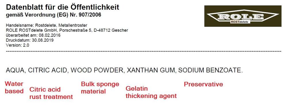 Snuggles.
I was thinking the same thing when I was reading about the difficulties of getting that pin out. Seems like it should be a relatively simple matter of pushing that pin backwards using the shaft as the "anchor" for some kind of device to hook on*. In fact, if the large end of the pin (the non threaded end) is not proud of the surface on the fork casting, you wouldn't even need a recess for the pin to press through. Since it's tapered, all you need to do is break it free a little and it should move much easier after that. * Proof is left to the student?
I suspect it was the cussing. That sometimes works for me too.
LOL! The IC's have numbers on them, but there's no info (that I can find) anywhere about what's inside. My assumption is that they are parts made by Hitachi for use only inside Hitachi produced devices and they didn't publish datasheets for them outside their own business. So you put a lamp in place of one injector and it blinked. That tests one output transistor. Can you move the lamp around to the other injectors and make sure the second output transistor is "working" too? If the wiring harness hasn't been messed with, I believe the injectors are grouped 1-2-3 and 4-5-6. You can pull the ECU off the harness and Ohm out the wires to the main ECU connector if you have to. As for the altitude compensations and stuff like that... The cars that did not need that stuff (non CA?) simply did not have them installed. My assumption is that the ECU defaults to "normal" non-altitude corrected if the other stuff is just left as no-connects. In other words, I strongly assume that you can just leave all the altitude compensation pins unconnected and it should work like a 49 state version.
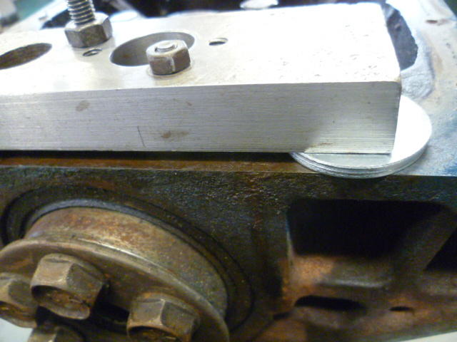
My build buddy hit the PCV screen holder screws with an impact and said they came out easy-peasy. Thanks for the info guys. On another topic, this was my experience pulling that troublesome rear main bearing cap. I made this little puller adapter contraption from a scrap parts I had laying around. Riddled with extra holes from previous fixturing and holding uses. Anyway, couple holes and some threaded rod: Put it on the rear main cap and run the three threaded parts down into the holes in the cap. The two smaller threaded parts get threaded into the oil pan mounting holes while the larger part goes into the other threaded hole in the cap. Put a couple washers under the puller as jacking points and then run the nuts down against the puller to lift the cap out. It's not pretty (or symmetric), but it's what I had laying around. When you run the nuts down, it pulls the cap out a little. Keep stacking washers and repeating the process until you have the cap off: The FSM uses just the one larger threaded hole, but I found the bearing cap tends to cokk sideways as you pull it. I found I could keep the cap even and pull much straighter out if I used the oil pan mounting bolts as well as just the traditional puller hole.
Snuggles.
I was thinking the same thing when I was reading about the difficulties of getting that pin out. Seems like it should be a relatively simple matter of pushing that pin backwards using the shaft as the "anchor" for some kind of device to hook on*. In fact, if the large end of the pin (the non threaded end) is not proud of the surface on the fork casting, you wouldn't even need a recess for the pin to press through. Since it's tapered, all you need to do is break it free a little and it should move much easier after that. * Proof is left to the student?
I suspect it was the cussing. That sometimes works for me too.
LOL! The IC's have numbers on them, but there's no info (that I can find) anywhere about what's inside. My assumption is that they are parts made by Hitachi for use only inside Hitachi produced devices and they didn't publish datasheets for them outside their own business. So you put a lamp in place of one injector and it blinked. That tests one output transistor. Can you move the lamp around to the other injectors and make sure the second output transistor is "working" too? If the wiring harness hasn't been messed with, I believe the injectors are grouped 1-2-3 and 4-5-6. You can pull the ECU off the harness and Ohm out the wires to the main ECU connector if you have to. As for the altitude compensations and stuff like that... The cars that did not need that stuff (non CA?) simply did not have them installed. My assumption is that the ECU defaults to "normal" non-altitude corrected if the other stuff is just left as no-connects. In other words, I strongly assume that you can just leave all the altitude compensation pins unconnected and it should work like a 49 state version.
My build buddy hit the PCV screen holder screws with an impact and said they came out easy-peasy. Thanks for the info guys. On another topic, this was my experience pulling that troublesome rear main bearing cap. I made this little puller adapter contraption from a scrap parts I had laying around. Riddled with extra holes from previous fixturing and holding uses. Anyway, couple holes and some threaded rod: Put it on the rear main cap and run the three threaded parts down into the holes in the cap. The two smaller threaded parts get threaded into the oil pan mounting holes while the larger part goes into the other threaded hole in the cap. Put a couple washers under the puller as jacking points and then run the nuts down against the puller to lift the cap out. It's not pretty (or symmetric), but it's what I had laying around. When you run the nuts down, it pulls the cap out a little. Keep stacking washers and repeating the process until you have the cap off: The FSM uses just the one larger threaded hole, but I found the bearing cap tends to cokk sideways as you pull it. I found I could keep the cap even and pull much straighter out if I used the oil pan mounting bolts as well as just the traditional puller hole.


Important Information
By using this site, you agree to our Privacy Policy and Guidelines. We have placed cookies on your device to help make this website better. You can adjust your cookie settings, otherwise we'll assume you're okay to continue.