


Namerow
-
Joined
-
Last visited
Posts posted by Namerow
-
-
On 1/19/2018 at 3:04 PM, zKars said:
Yeesh indeed. The only thing that is changed is the use of vintage air's generic laser cut Sanden compressor bracket to ease that part of the fab and my new found love for EZ-Clip AC hose fittings so I can make my own hoses more easily. The hoses are also smaller and have a tighter bend radius. Still pricey'r than generic crimp hose and fittings but worth it.
I was reading this thread out of idle interest and decided to check out Jim's recommendationre the EZ-Clip hose fittings. Look's like a great solution for aftermarket AC installers. Check out this Eaton Corp. video for details...
-
 1
1
-
-
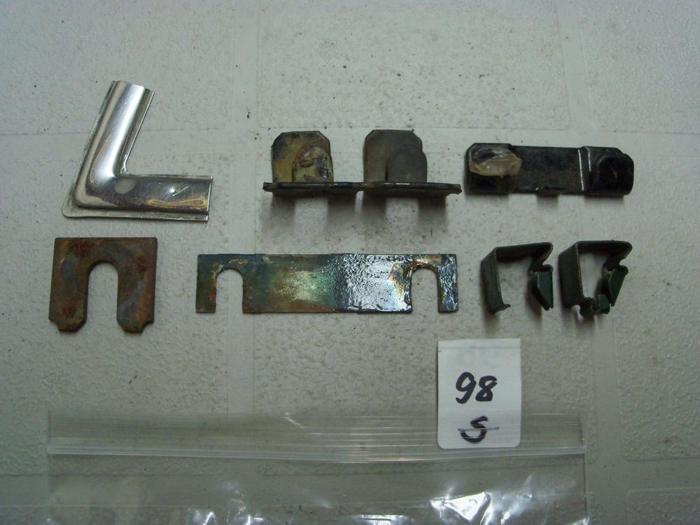
Among all of the assorted little bits of hardware that I've accumulated over the years is a 'slotted' shim plate (lower row, centre, in the photo below). I could never figure out what it was intended for... until now!
If you find that you need something like this, it shouldn't be that difficult to to make up a pair from some sheet stock. Maybe make two or three pairs, so that you can stack them. If you go with metal, rust will be an issue so brass would be best (if you can find it this thick). It might be easier and better, though, if you make them from 1/32" or 1/16" clear plastic sheet stock. A little more fragile for installation, but easier to fabricate and zero rust issues. A quick cruise of your local hardware store's shelves should turn up lots of items that could be used as material donors.
-
1
-
-
If the locating pin on the old control arm was bent, you may want to check for frame damage back there too. Look for a wrinkled wall on one of the reinforcement 'ribs'. At some point in its life, the car may have slid off the road and smacked a curb with the rear wheel (easy to do in the snow). Probably a separate incident from whatever caused the frame twist up at the front. Hopefully, it just bent the LCA pin. Maybe somebody else who's seen similar LCA damage like this can comment.
-
-
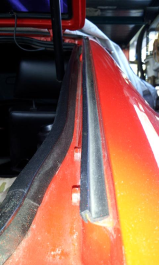
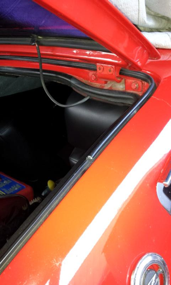
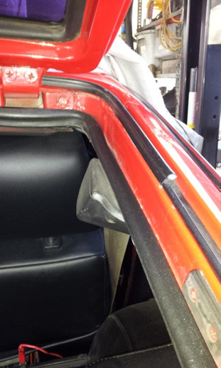
Not sure why you've had problems, 'breaking these when I close the hatch'. Maybe you can explain where the problem is occurring. Pix #1-3, below, were posted by another CZCC member (sorry, no name to credit) and show the OE-style, 3-piece outer seal. It uses a bulb-type seal across the top and around the upper corners. After that, the bottom pieces on the left and right are -- as Jim says -- really just water gutters, rather than seals. The aftermarket, one-piece seal uses a bulb design along its entire length
In my experience, the top piece was difficult to install properly with the hatch in place. Also, the metal lip on which this seal mounts isn't that deep, so you shouldn't really rely on just a mechanical fit to hold the seal in place. Some judicious use of weatherstrip cement is called for here (see photo #4). If you've just been pushing the seal into place and hoping for the best, that may be the source of your problems.

-
1
-
-
Edited by Namerow
further comment added10 hours ago, Elliott000 said:I am a bit nervous about the quarter repair tho. I basically need thier panel but right down to the bottom.
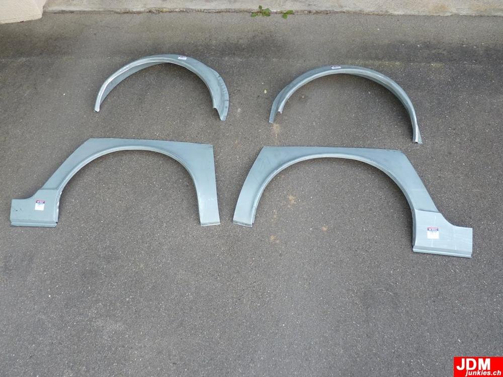
This photo may help you understand the details for the Tabco rear-quarter patch panels. Unfortunately, it doesn't answer your specific question, because the door jamb edge can't be seen on either panel. Looks like they may be difficult to integrate properly unless you also replace the outer wheel housings (also shown in the photo) so as to get a decent bonding/sealing surface around the lip. The four pieces will probably cost Cdn $800 - $1000 after you've paid for shipping, tax, duties, etc.
-
-
I think the chemical engineers designed that old brake fluid in keeping with the idea of owners trading in their vehicles every four years or so. How many people do you know who actually ponied up the money for a brake system flush? Oil and filter replacement? Absolutely. Maybe even a can of STP or top-cylinder lube. Ignition system tune-up kit? Of course. New brake pads? OK, if I really have to. But new brake fluid? I think not.

-
1
-
-
11 hours ago, TomoHawk said:
My wiper linkages have been cleaned to death, and I lubricate (with DeOxit and light oil) everything regularly, especially after driving in the rain, so I'm sure that's not why its swiping slowly. Sarah (FastWoman) mentioned to me that she was successfully able to restore the speed of her wiper motor by jut cleaning the internals and the power contacts. It makes sense, but the insides are very complicated, IMO.
Not sure what you are including when you say, 'wiper linkages', so just in case: The main cause of slow wipers isn't the linkage joints. Instead, it's dried-out bushings for two stub spindles that the wiper arms are mounted to. The grease used by the factory for these bushings seems to coagulate over time and ends up performing like 'anti-grease'. Some owners have claimed that cleaning and re-greasing these bushings makes it unnecessary to upgrade the motor. I'm not sure I'd go quite that far, but it does make a big difference.
-
Given the traditional reluctance of (mainstream) auto manufacturers to spend money on parts not vital for a functioning and legal-for-sale vehicle, it's interesting that someone within the Z's product design/engineering team was able to recommend and get approval for these competition-use-only attachment points to be installed in every one of the tens of thousands of cars that were going to be produced. That's eight (maybe twelve?) captive nuts, individually tack-welded in place.
-
3 hours ago, Zup said:
expected to see a photo showing your feet under the car up on wood blocks used for jackstands with a tub of grease in your hand.
I was instantly a fan of anyone who could do those kind of repairs and mods while lying underneath a jacked-up car parked outdoors on on a crushed-rock driveway. None of that 3-bay-garage, epoxy-coated floor stuff for our Mr. Blue.
Always made me wonder, though: Aren't there any mosquitoes or blackflies in Nova Scotia?
-
2
-
-
-
The plugs are conveniently available (in various colors) from any of the leading suppliers of Z replacement/accessory parts. Try any of these:
- Motorsport Auto (Los Angeles)
- Z Car Source of Arizona
- Z Car Depot (St. Louis)
- Banzai Motorsport (Virginia)
BTW, the plugs don't have to be broken to remove them. Just push the center pin all the way through (can't be extracted - sorry), then use a forked trim-removal tool to lever out the plug. The center pins typically fall down into deep recesses in the body cavities. If you rig up a length of 1" rubber hose on the end of your shopvac hose, you can probably recover most of them. A plug without the center pin is useless.
Brand-new plugs and pins are easier, of course. Depends on how frugal you are.
Be careful not to flex the plastic panels too much when your re-and-re-ing them (especially the one that covers the antenna location). They're a lot more expensive to replace than the plugs. Note, too, that the panels don't react well to overzealous use of heat gun to make them flex better. A blow drier is a better bet.
-
Here in my part of Canada, we are fortunate to have access to Rick Scott, parts dept manager at Brantford Nissan (Brantford, Ontario is a small city located about 60 miles west of Toronto). Rick is a long-time Z owner, restorer and enthusiast who knows the cars, the parts, the company, and the customers. He and the dealership make their lot and service area available for a Z-parts swap meet once a year.
By contrast, my local Nissan dealership couldn't care less.
-
1
-
-
14 hours ago, Elliott000 said:
I think ill go the route of multiple pieces attached to make a final form.
Grannyknot did some comparable fab work when he modified the front crossmember on his 240 to provide clearance for the sump of the BMW he was installing. Maybe he can post a sketch of how he'd go about fabbing this part.
Great reference pix posted by 240260280. Notice the doubler plate that's installed in the region right next to the shock tower.
-
2
-
-
2 hours ago, Elliott000 said:
Dude that's awesome and I really appreciate all the research! I've got my tower braced right now at about 907 center to center while I've been working on the rails and inner fenders. I'm currently re attaching the fenders to the frame and have confirmed number in the vertical on both sides are the same. I'm pretty confident that everything will line up. I laid one of my old fenders on there and bolted on the door. Checked gaps etc because of having to lift the one side, i was worried it may cause issues but shes spot on. I measured the hood just now and it "seems" as though there will be sufficient gap for it to close low n behold the gap is same front and rear in relation to hood width.thi g's are looking up! In the topic of this actual thread. Once I finish the tie in, I'll be onto the over wheel air things. Should be fun.... I still haven't decidied on what the plan is haha. Maybe full on tin basher, or I might do card board cut outs and basically replicate it but with square corners essentially boxing it.
Sent from my SM-N950W using Tapatalk
The 'air horns' (aka 'over the wheel air things') are apparently known in more polite circles as the 'upper beams'. I suppose the ones on the bottom should therefore be called the 'lower beams', but we've all decided to keep calling them 'frame rails', because that's what they were/are called in body-on-frame designs ('side rails').
I'm pretty sure that these beam stampings were made from extra-heavy-gauge steel. In fact, I've got a dimension of 0.054" in my notes (with a credit to Z-guru, Carl Beck). That's at least 18 gauge (maybe 16), so considerably beefier than the wimpy 0.032" / 20 gauge stuff used on the exterior panels. Remember that these upper beams take most of the vertical loads from the suspension, so there's a reason why they need to be strong. According to Carl, the wall thickness of the lower rails is a bit less, at 0.050". Maybe someone else can confirm or correct on these panel thickness numbers?
It would probably be tough playing panel-beater with 16 or 18 gauge. Maybe -- as Grannyknot suggested earlier -- you could fabricate the piece from a set of smaller pieces. I'm thinking bent-to-shape vertical strips (2" wide?), tack-welded together into a final form. Maybe make a wood buck, then lay in the strips, one after another, bending in-place and then tack-welding as you go along. To make it easier, you could perhaps used 20-gauge and then lay some lengthwise gusset strips along the inside surfaces to add some bending strength.
Whatever you do, remember to post some pictures for the rest of us to look at.
-
On 5/2/2018 at 10:34 PM, Elliott000 said:
I've got a center line and plumb bobs off the strut towers for reference measurement. BUT i do have a discrepancy of 7mm or about 5/16 of an inch on the dimension between towers.
Hi Elliott:
Hope this note arrives in time to be useful...
Your comment about your shock towers measuring at 906mm separation distance caught my attention, so I asked a few other CZCC members offline if they'd mind measuring that distance on their own Z's (none of which have experienced any collision damage). I've received 4 measurements:
Owner #1 - 240Z: 905mm (measured between the centres of the shock tower cover 'buttons')
Owner #1 - 280Z: 906mm (ditto)
Owner #2 - 280Z: 905mm
Owner #3 - 280Z: 916mm (measured to the centres of the top surfaces of the strut rods)
All three are well-known and well-respected members of the CZCC community (they can self-identify if they want
") ), so I trust their measurements.
), so I trust their measurements.
You can make of this what you will. To me, it suggests that the factory may not have been that successful in assembling the cars to meet this particular part of the dimensional design spec.
I've done a lot of reading on unibody structures over the past few weeks and it appears the manufacturing tolerances of +/-3mm were accepted on 'long' dimensions like this in the 1960's and 1970's. That would allow a car with a 910mm shock tower separation to pass inspection on the line.
That said, we now have three cars that measure 6mm - 7mm under design spec. i.e. 100% more than 'acceptable'.
What does the distance between the front shock towers affect? The obvious answers are: 1) suspension camber angles, and; 2) hood-to-fender bodyline gaps.
Camber Angles:
A 3mm inboard movement of the top of the suspension struts amounts to 1.5mm on either side. That gets played out over a strut length of about 250mm. So -- if my grasp of high school geometry hasn't slipped too badly -- that's the equivalent of adding 0.35 degrees of camber on either side. Double that, to 0.7 degrees, if the shock tower separation is 6mm under spec.
I've read that most passenger cars with strut-type front suspension run a static camber setting of between 2 - 3 degrees (positive). My feeling is that making that less positive by 0.35 - 0.7 degrees isn't going to affect the car's road manners that much.
Of course, if the change in the shock tower separation is the result of accident damage that plays out on only one side of the car (i.e. one of your towers has moved inboard by 7mm), then you can double all of these numbers.
Hood-to-Fender Panel Gap:
Based on visual evidence, 1/8" to 3/16" seems about right. That would be 3mm - 5mm, so 4mm nominal. The width of the hood outer stamping is probably going to be consistent to +/- 1mm from one car to another. If 913mm really is the target, then regular production tolerances ( +/- 3mm) would allow this to be under by 1.5mm on each side. Combined with a hood that over-spec in width by 1mm (or 0.5mm on each side), then the hood-to-fender gap would shrink from the nominal 4mm to 2mm. That's about as tight as you'd want to get for these cars. If the shock tower separation distance is only 905 - 906mm, that implies that the hoods for Owner #1 and Owner #2's cars won't be able to close without hitting the fenders. But they do. And that makes me wonder whether the FSM design spec of 913mm is either wrong, or was purposely published at the high end of 'tolerable' so that there would never be hood closure problems (i.e. the spec should really be read as '913mm, +0 / -6'... or maybe +0 / -8).
For purposes of what you're doing to get your Z back on the road, my thinking is that you may not need to bother spreading the tops of the shock towers apart in order to be assured that the hood will close. In fact, that may end up simply generating extra-wide gaps between the fenders and the hood edges. From the evidence of the measurements supplied by Owner #1 and Owner #2, we seem to have some degree of assurance that your hood will close just fine with your shock towers sitting at their current separation distance of 906mm. Your call, though.
-
2
-
-
On 5/18/2018 at 7:25 AM, Namerow said:
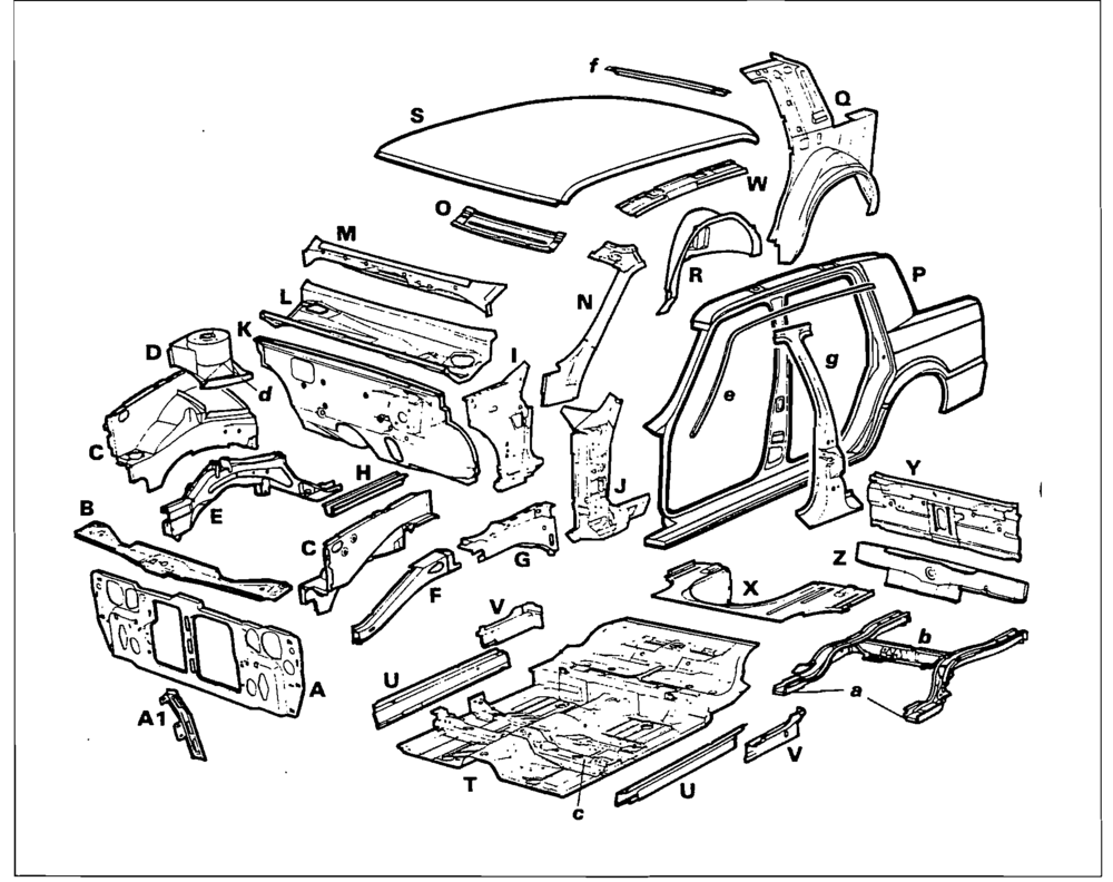
Further to Grannyknot's comment, I suppose you could be tricked by certain diagrams into thinking there's a separate frame...
... but there really isn't. It's just a collection of panels, ribs and rails, all spot-welded together.
Here`s a more complete illustration of the set of panels that make up a typical unibody structure (not a 240Z, but remarkably close)...
-
9 hours ago, Elliott000 said:
In Canada, if the car was previously registered with a clean title then im good to go. As far as the safety side of things go, let's be honest there is a danger factor in this setup ill agree to that. Theres also danger inherent in driving my lifted truck over 80 km if I swerve hard with no sway bars she will probably be on it lid. If i hit something head on in the 240 and put the engine into my nuts I don't think the frame rail will be of my biggest concern. On the other hand, Im more concerned about getting driven over in this low arse car. I appreciate that some people, And I don't really know what u guys mean when referring these porsche types.... But some. Guys might not be happy with the way certain things get done and not only on my build. In my case, I got a rusty z, ive always wanted one, and I'm goin to build this one to the best of my ability and budget, and when it's done I'll enjoy and try my best to avoid any trees. If it's an auto mobile vs automobile accident chances are it will happen at some sort of angle or ill drive under a truck and cut my head off anyway.
Wins my vote for, 'Reply of the Year'
 . Hope you didn't take my 'Porsche' comment the wrong way. I am always impressed by this type of 'git 'er done' resourcefulness and outside-the-box thinking. As for the 2mm-wall steel tubing, there was a day when almost all cars were body-on-frame and the concept of, 'crush zones' didn't exist. As you correctly point out, the only person possibly at risk here is you (and your passenger). Keep us posted on your progress. I'm learning a lot from the solutions you're developing along the way.
-
1
-
-
Resourceful and fearless. Thanks for the pix. Red Green would be proud. It's a good thing that there aren't any Porsche types on this site. They'd be apoplectic after seeing this kind of solution!
Speaking of 'resourceful', my old friend Kees Nyrop (Porsche hero and past winner of the Sebring 12 Hour race -- you can look it up) is also a 240Z fan and built a rotisserie for his restoration out of lumberyard wood. He lives in Kelowna.
-
1
-
-
-
If and when you do any pulling to take out the twist, here are some safety tips that I found online. They're not all appropriate to a unibody repair or to the type of repair you're going to attempt, but they'll give you something to think about...
- Inspect clamps and chains before each use.
- Wrap chain around a frame member several times. Do not twist the chain.
- Place padding around sharp corners of frame members that rub against the chain links.
- Ensure that the chain hook is connected to a link with a firm grip. Test it before applying tension or hydraulic pressure.
- Place a heavy blanket over the chain and clamp before pulling to minimize fly-back if the chain breaks.
- Stand to one side of the chain, not behind it. Stand behind a strong acrylic plastic or safety glass shield during all but the lightest pulls.
- Use two or more chains for pulls that require a great deal of force.
- Reinforce weak parts before pulling.
- Check the level of hydraulic fluid.
- Inspect hoses and connections frequently for leaks and general condition.
- Screw all body attachments (clamps or hooks) on tightly. Avoid damaging threads on the attachments.
- Replace damaged links with same quality and size of link. Do not use temporary threaded links for high stress applications.
- Teeth of clamps need to be clean and dry.
- Inspect clamps and chains for wear. Replace clamps that have worn teeth. Replace the chain if it is nicked or otherwise damaged. Make sure the chain is rated for the intended pulling force, including a large safety factor.
- Remove all undercoating where the clamp is attached.
- Before attaching the clamp to a rusted panel, tack weld a metal brace to the panel for support.
- Have the vehicle on its wheels or bolted to mobile safety stands when pulling. This prevents the vehicle from falling off the stand during the pull.
-
1
-
Edited by Namerow
comment added about FSM vs. actual dimensionsCharles:
Would you mind also measuring between the centre of the front shock towers, if convenient? FSM says 913mm.
Interesting that your measurement of the pinchweld separation distance (51.25" = 1302mm) is smaller, rather than larger, than the 1326mm value I got from scaling off a screen blow-up the FSM diagram. The difference is almost exactly 1.0"... which makes me suspicious.
-
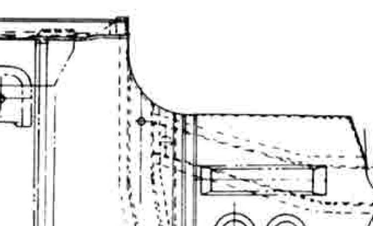
Nope. I think the 'C' point is something that you have to mark for yourself, based on the visual info inferred (implied?) by the FSM diagram. It seems to be in line with the outboard wall of the longitudinal rear sub-rail where that rail ties into the front transverse sub-rail, and then positioned dead-centre on the front transverse sub-rail. Note that there is a hole (factory-punched) in the transverse rail in that vicinity, but it sits about 1/2" outboard of the location that the FSM diagram suggests. Who knows? Maybe the punched hole is the C-point. It would certainly serve quite nicely for purposes of fore-aft measurements, but it would be off a bit for width-wise and diagonal measurements. See pix below (and, again, apologies to the unknown owner of the newest photo I'm about to post):


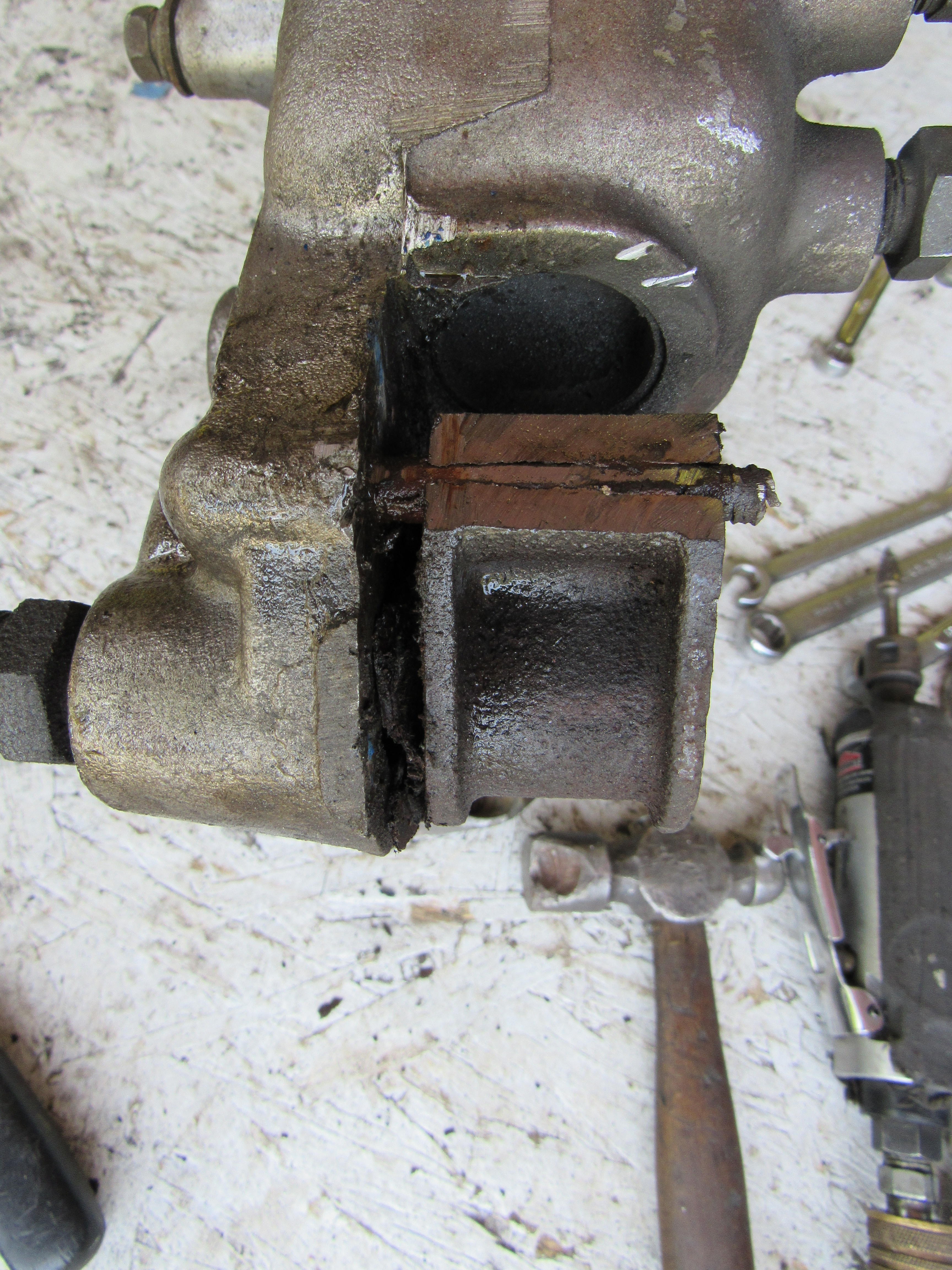
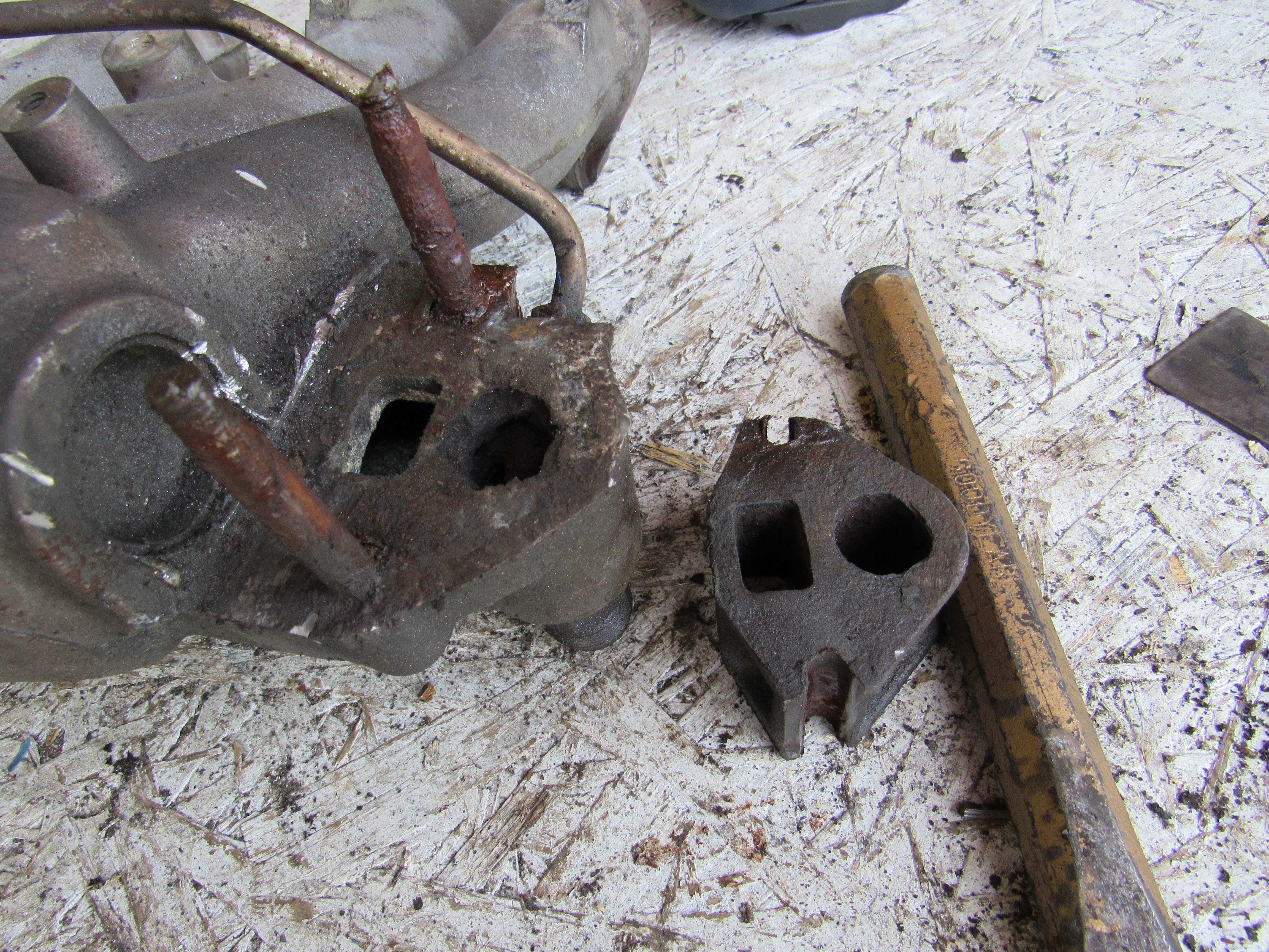

How Do I hate Rebuilt Components? Brake Booster
in Wheels & Brakes
Here's a picture of that tool, copied from 240260280's rebuild write-up on the old AtlanticZ website. A pragmatic solution (and environmentally sustainable, too!)