Namerow
Free Member
-
Joined
-
Last visited
Everything posted by Namerow
-
 The springs that appear in the ebay vendor's site (PN 951606) are not listed in the 2015 Vogtland catalog. They're probably a discontinued item. The 2015 catalog contains no parts listings for the 240-260-280Z's. Before you buy, you may want to check with Vogtand customer service in Germany ( http://www.vogtland.com/en/contact_persons.php ) to make sure that these are the correct parts for a Z and that the characteristics (stiffness, amount of drop) are going to be acceptable for you. A quick read of the Vogtland company materials indicates that you should have no worries about product quality or customer support. If you manage to get the specs for these springs, please remember to post them here on the CZCC site. I suspect that a lot of other Z owners may be interested.
 -
Re the brand of brake shoes that MSA sells, I think you mis-heard the sales rep. It's 'Valeo' -- one of Europe's largest automotive parts manufacturers for both OE and aftermarket applications. You can review their service parts catalogue here: http://www.valeoservice.com/html/export/en/produits.catalogueproduits.php Valeo started out in business in the 1920's as 'Ferodo' making brake and clutch linings. They moved into heaters and air conditioning systems ('SOFICA' brand) in the 1960's, and then into electrical systems ('Marchal' and 'Cibie' brands) in the 1970's. Originally a French company. Tt now has plants all across Europe, as well as in the USA, South America and China.
-
Motorsport Auto sells a product called 'Battery Mat'. It's an acid-resistant, absorptive sheet that fits inside the plastic battery tray. Under $10, IIRC. Can't vouch for its long-term effectiveness -- probably good for one or two incidents. Way better than the alternative, though.
-
I have the next-smaller size of the Eastwood series . It's loud. I put in in a separate room and close the door. These things aren't, '5 minutes and you're done'. More like several hours (of noise). I use the pyramid-shaped green media for the de-rusting step. I'm not sold on this design as a 'one stop solution' for de-rusting fasteners. I suspect that use of a powered brass wire wheel may still be a worthwhile pre-treatment (although I bought the Eastwood shaker to get away from that). Someone else in another thread has provided a lot of suggestions about adding detergents to the media. Check that out. In the end, I suppose these 'tumblers' have a place in the workshop, esp. if your budget doesn't permit buying all-new fasteners like some do. The idea of media-blasting fasteners seems a little silly, and chemical de-rust treatments leave a residue that isn't very attractive. The real issue is what to do after you've de-rusted the fasteners. Paint? Plating service? I'm playing with a DIY plating rig. Results are promising but the jury's still out. Not sure if I'm up to doing this with all of my de-rusted fasteners. Life is short.
-
Might be easier to find and install a different balance tube than to find a early-style, engine-side vacuum hose that's in good condition. I have the same issue with my 5/70. I measured both the OE hose (tattred braiding, ok hose) and the brass fitting and found that they're 'odd' compared to all of the other S30 hose fittings: Hose ID: 9.5mm Fitting OD: 10.75mm Hose 'stretch' over fitting: 13% Hose Wall: about 4mm (compares with 3.5mm measured for an OE coolant hose... | 10% thicker wall) Unfortunately, all that`s out there in the way of braided hose is 9mm or 11mm (ID), both with a coolant-hose-type wall thickness. Neither is suitable for the Nissan OE fitting -- one is too small, the other too big, both are too thin. But: An 11mm hose with a formed metal-tube liner/shaper might work -- if you properly seal the two ends over the slightly-too-small OE fittings. Just thinking out loud, here...
-
Some further insights into wiring for a dealer-installed aftermarket A/C system, as posted by member 'AZ 240z' on 21 January 2014: "The dealer added FrigiKing air conditioning incorporated a micro-switch that may have utilized one of these wires. The micro-switch was mounted at the intake duct actuator located behind the blower motor in the passenger side footwell area behind the dash. When the top slide lever on the heater control panel was moved from the center "vent" position to the left "off" position, the intake duct door moved to close off fresh air intake and open to allow the air from the evaporator to pass through the blower assembly for cabin distribution. Also, with the movement of this vent lever to the off position, a circuit was completed via this micro-switch through the dealer added A/C ON-OFF/ RHEOSTAT switch to allow electrical actuation of the A/C compressor. This on-off switch was mounted to the bottom of the dash below the hazard switch. The micro-switch assembly on my car is incorporated in a red plastic housing mounted next to the cable actuator for the intake duct behind the blower motor." I believe that the FrigiKing A/C system was just one of the two or three different aftermarket systems that were installed by Datsun dealers back in the day. The choice of system may have depended on the sales region, or it may have been simply up to the individual dealer (carl Beck would probably know more on this). They probably all operated and were wired in much the same way. So: The wire connection point you're looking for may, in fact, be at the microswitch that is, "mounted at the intake duct actuator located behind the blower motor in the passenger side footwell area behind the dash." I wonder if anyone else has ever posted a wiring diagram for one of these aftermarket A/C systems?
-
According to carpartsmanual.com, the Instrument Harness went through a series of PN changes in the early days of the S30. Not sure, though, exactly what this means with respect to actual changes in the design and features. The production periods for the first five (of many) iterations were: 1 SOP - 7009 2. 7010 - 7012 3. 7101 - 7108 4. 7109 - 7112 5. 7201 - 7206 My May-70 car has an Instrument Harness whose design matches (mostly) with the factory wiring diagram labeled, 'Late Model' that appears in the 71 FSM Supplement. The next available FSM wiring diagram appears in the 72 edition of the service manual (and probably a lot of the 'transition' cars' built in the few months leading up to the formal start of MY-72 in/around Oct 1971). Your car's Sep-71 build date falls squarely in that transition period, so who knows what you've got and what wiring diagram and PN apply. There is a label with the PN that's taped into the Instrument Harness loom, but you'd have to pull the dash to find it. FWIW, the owners manual that was shipped with your car might have a wiring diagram at the back. In the case of my May-70 car, this version has proven to be the only one (of the three or four possible) that accurately depicts the wiring and switching that's in my car. If you have an owners manual and you know that it's the one that was shipped with the car from the factory, it may prove to be the only accurate reference for your car's wiring. SteveJ is an expert on these cars' electrical details, so perhaps he can comment further. The equipment anomalies of the MY71-MY72 'transition cars' has been the subject of owner comments in many past threads on this site.
-
Not surprised you couldn't find the earlier reference. I posted it in a thread about a 4-relay system for headlights and I referred to what you call the 'bowl' as a 'bucket' (we're all colonials over here and we use different words). Anyway, the bowl that I have was purchased new some thirty years ago and has sat in its box ever since. It's ink-marked 'L' on the back face of the mounting flange, and that means its designed to be mounted on the 'traffic' side (as opposed to 'curb' side) here in North America. Looking from the front of the bowl, the mounting tab for the alignment tensioning spring sits at the 7:30 position. My LHS unit has to following info stamped,into the front face of the mounting flange: "110-24152 Koito Japan SAE H 69 DOT" There is a second stamping, located on the stamped-metal headlamp mounting platethat, itself, mounts to the bowl: "10-41371 Koito Japan" This leads me to believe that the numbering is just Koito's internal parts numbering (i.e. not a date code). Nissan PN for the complete (from the label on the original box) is 26060-E4601. It includes outer bowl (c/w 4 body-mount bolts), headamp mounting plate, alignment tensioning spring, chrome trim ring, rubber mounting gasket, alignment screws and plastic bosses, 3-wire electrical pigtail c/w black plastic and white plastic connectors, connector dustboot, and rubber grommet (where the pigtail passes through the bowl).
-
Different part numbers, FWIW. Changeover was as of 7409. Part number changed again in 7608. Hard to say, though, whether the PN changes mean that the rails are/are not interchangeable.
-
Both the metal headlamp bucket and the black plastic connector for my headlamp assembly are labeled as 'Koito' (stamped into the metal part, molded into the plastic part). FWIW, the brass wire-end terminals at the lamp end of the pigtail are all the same size. Same goes for the brass wire-end terminals at the harness end.
-
I have a brand-new LHS headlight assembly sitting in front of me (PN 26060-E4601). According to carpartsmanual.com, this (and the matching RHS assy) were used up until July 1973. Some details, for those interested: Pigtail length (exposed length, from exit of headlamp bucket to start of white connector plug): 23" Wire colours (continuous, plug-to-plug):RW - hi-beam... marked 'Drive' on the lamp-end, black connectorRB - lo-beam... marked 'Pass'B - ground... marked 'Ground'All 3 pigtail wires are 16GA (which is interesting, given that the 'arriving' wires from the engine harness are 10GA, 12GA and 14GA) T-connector terminals (viewed from plug-in face): LAMP PLUG HARNESS PLUG Top RB B Bottom-left RW RW Bottom-right B RB In other words, the B and RB terminal positions switch places from lamp plug to harness plug (necessary to let Nissan mate it's oddball headlamp switching/grounding arrangement to the standardized terminal positions on a sealed-beam headlamp unit?). Unfortunately, I can't find my RHS headlamp assembly at the moment, so I can't verify directly that the pigtail is the same. I do know, however, that the mating headlamp plugs on the engine harness use identical wiring orientations, LHS to RHS. That is, the LHS and RHS plugs are not mirror images. Instead, both have the RW wire located on the driver's side and the RB wire on the passenger side. This same-ness is reflected in the wiring diagram.
-
And then there's our friend, the moose. Not so many of them as there are deer, but they're slower and a lot bigger. They will destroy a car if you are so unfortunate as to hit one at speed. Not a happy event for the moose, either.
-
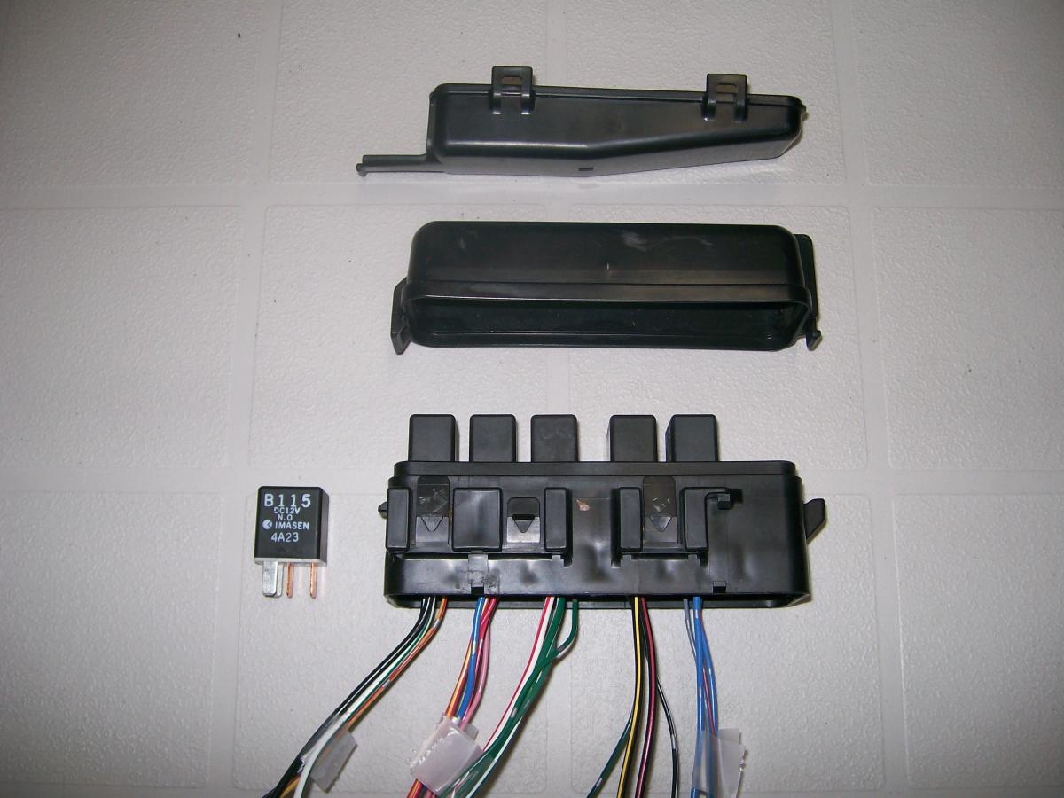
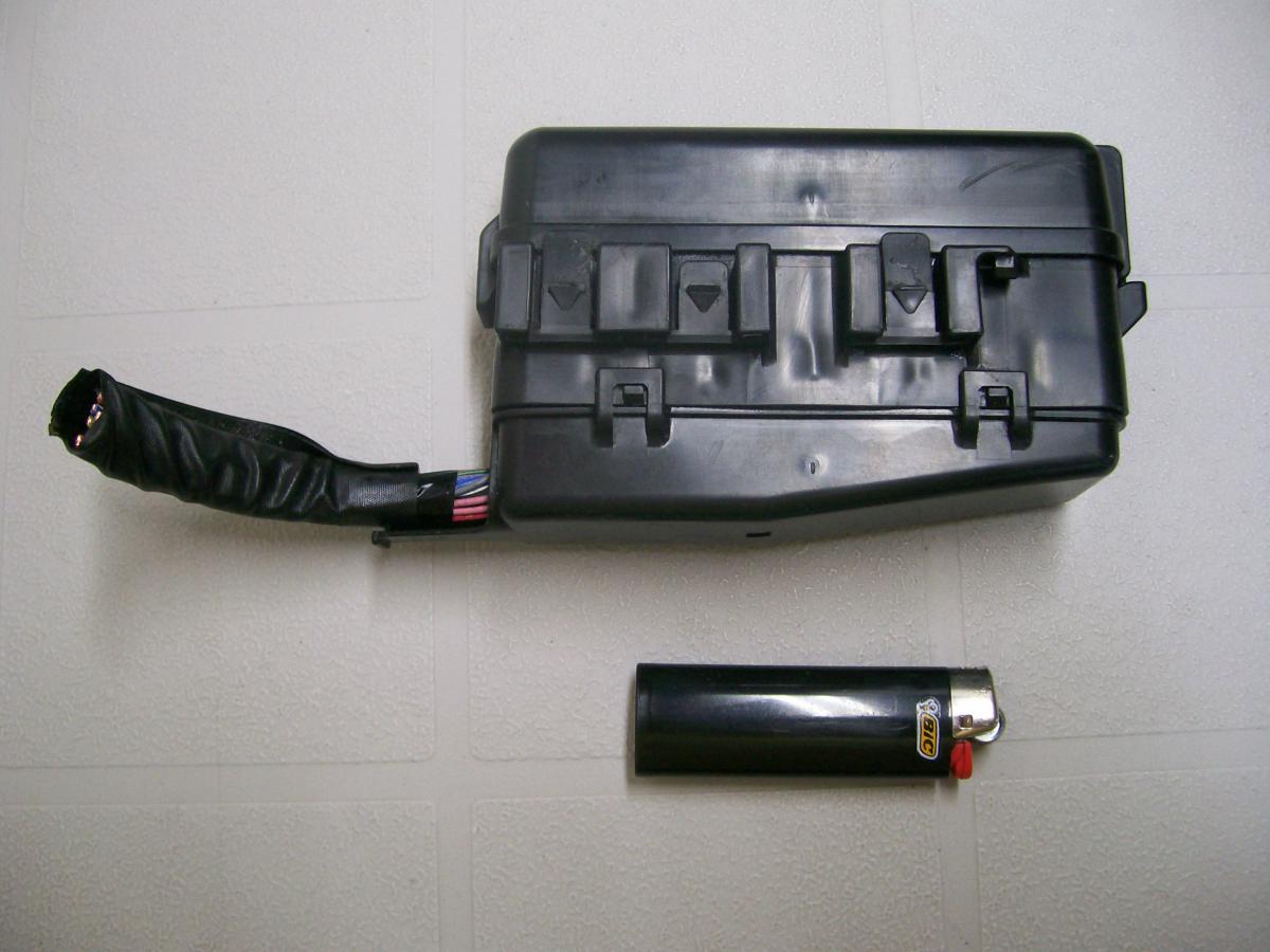
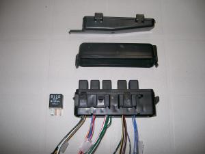
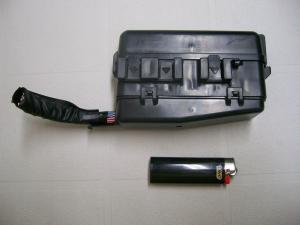
Thx for the additional input. I think that's pretty much in line with what I've sketched out. I'm aware of the Starter relay possibility, but haven't been able to convince myself that it's really necessary, given that the Starter's solenoid seems to be already there to serve exactly the same purpose. Do I really need a relay to operate a relay? Your thoughts on this? About the MPV relay block: It has no sockets for fuses. Just relays. The relays were mostly of one spec and terminal configuration, but one was quite different. That one used a white-plastic adaptor socket at its base to match its connector blades to the basic socket configuration that's molded into the base block. I pitched all of the oddball relays and their plug adaptors and will be using all-identical relays (made possible because I took away two relay blocks from the pic-and-pull and used them to mix-and-match to create one to my liking). I couldn't find any specs on-line for the relays that I'm going to use, so I took one of the spares and levered off the protective housing. Underneath, I found what appears to be a standard-issue automotive relay. It uses a resistor (rather than a diode) to help protect the ECU and the other on-board computers from possible voltage spikes. In its original habitat, the MPV's relay block clips onto the side of a much bigger plastic box that I'll call the 'electrical centre'. The bigger box has a few more relays, along with many, many fuses. Both boxes are easy to get at -- they're up top, at the driver's-front corner of the engine bay. If anyone else decides that they like this unit, just be sure to cut the wires as far out of the relay block as you can. I was able to get about 6" of loose wire to play with, but not much more. Try to get two relay blocks. All of those loose wire ends from the relays will receive Nissan-issue brass connector terminals, which will then be inserted back into the white-plastic Nissan 3x2 connector blocks.
-
Already with you on that. The design I've come up with uses an 'intermediate harness' with Nissan T-3 connectors to plug into the engine harness at the appropriate places (when I said I was going to start cutting wires, I was talking about the wires for this harness and not about cutting into the car's engine harness). BTW, a recent search through the local pic-n-pull produced a very nice relay block, taken from the engine compartment of a 91 Mazda MPV. The casing has removable upper and lower caps, with all of the wiring entering and exiting at a common conduit at the front. The internal wiring and relay set-up was, of course, specific to the Mazda application. However, the wire terminals can be extracted from their sockets and moved around to suit a new requirement. I grabbed two of these relay blocks and have used them to produce a single block with 5 identical relays (4 for headlights, 1 for fog lights, one empty socket for possible future use for an electric engine cooling fan). The new, intermediate harness will be connected up to the relay block using two pairs of spare Nissan 3x2 connectors. The fog light relay will take its switching signal off the rhs pair of bullet-connector plug-in points up at the front of the car. Power for the fog lights will come off the alternator. Headlights and fog lights will now all be grounded to the chassis with dedicated local ground wires. The relay block will be mounted in the engine compartment, using the mounting bosses from the now-discarded voltage regulator (I'm using a 280ZX internally-regulated alternator, along with the MSA/Dave adaptor plug).
-
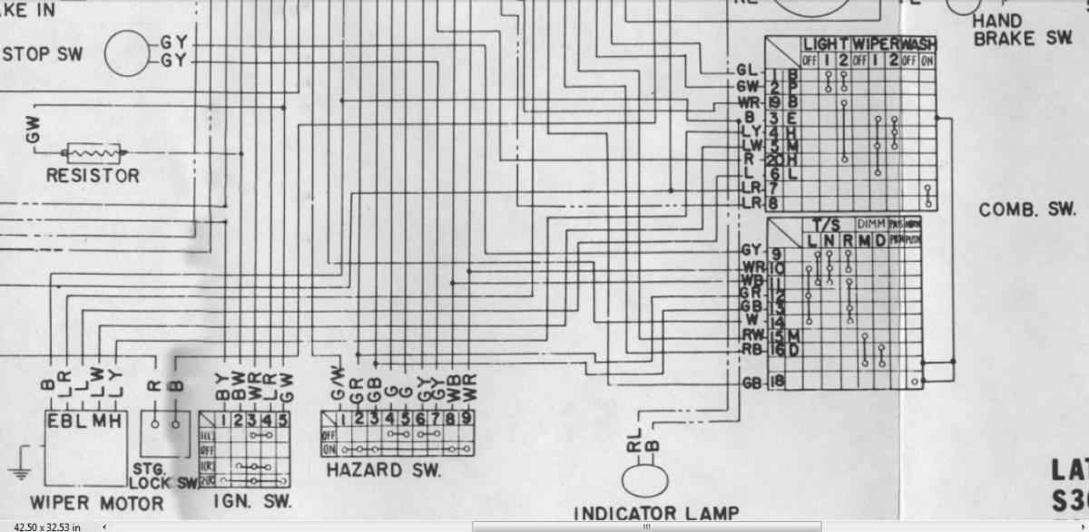
Thanks for the quick reply, Captain O (and thx also to Steve for chiming in on my original question). I wanted to be 100% sure before I start cutting and soldering for my 4-relay set-up. The two FSM-sourced electrical diagrams just didn't seem to line up with what I had in front of me (nor did the one from the Haynes workshop manual, or any of the other permutations that I've found on this site), so I'm really happy that you reminded me about the one I had sitting in a drawer in my Owner's Manual. Some trivia I noticed during this exercise: The wiring diagram in my 1970 Owner's Manual shows the #2 fusible link (at the Alternator) that the 71 FSM diagrams managed to omitUnfortunately, the 1970 OM diagram doesn't show the Accessory Relay that powers the Rear Defrost heating grid (although it at least shows the grid and switch)The 1970 OM diagram also completely omits the Blower wiring and control switchThe 1970 OM diagram has the pairings of the aux gauges mixed up (should be Amps/Fuel + Water/Oil, not Amps/Water + Fuel/Oil)Also: The embossed graphics for the Light/Wiper settings on my Combo Switch show a third (but unpainted) 'dot' for the Wiper speeds, hinting that Nissan was already planning to add an 'Intermittent' feature at some later date. Counting those in my 'spares' box, I have four Combo Switches on hand. They're all different!
-
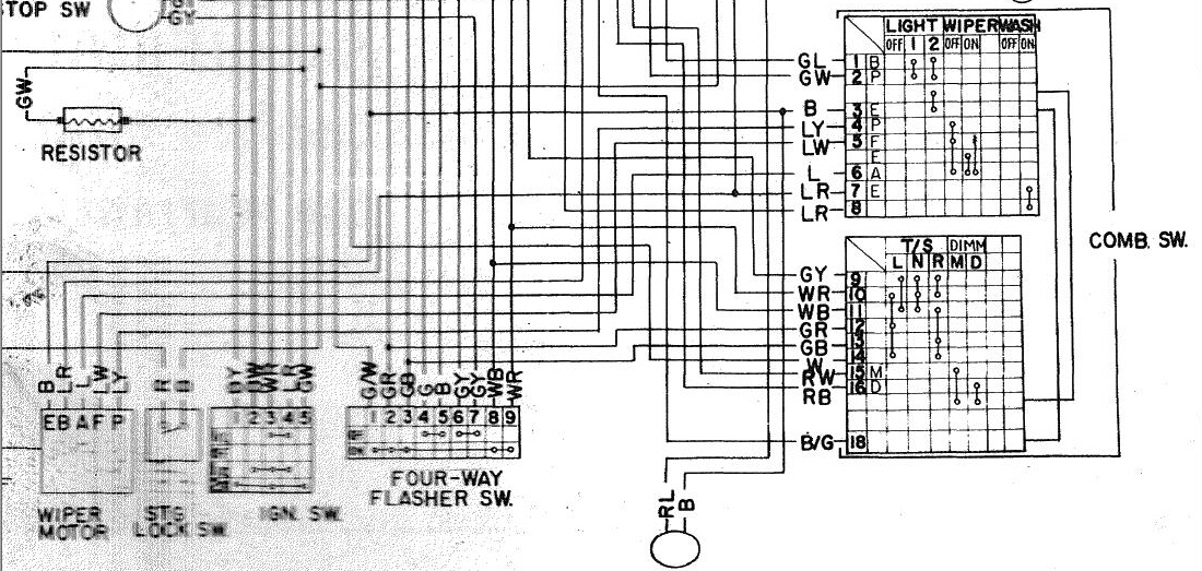
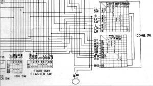
I should have added the full electrical diagram from the 70 Owner's Manual. Here it is, just as I scanned it from the hard-copy manual that came with my car... S30 Wiring Schematic - 70 240Z - B&W - 70 Owners Manual - v3 (darkened).pdf
-
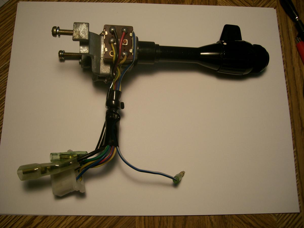
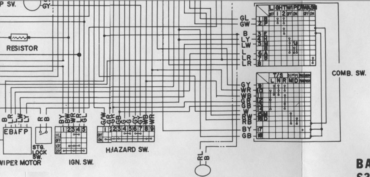
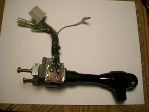
Ay chihuahua! There's another wiring diagram!! I forgot all about the tiny little version that's tucked into the back pages of the MY-70 owners manual (and humorously labeled, 'Minor Maintenance'... ha!) So now I've burned up another morning staring at yet another version of the wiring and connection logic for the early Z Combination Switch. This wasn't helped by the fact that the wires on the 'Lights' side of my car's combo switch are different from those shown in all three of the wiring diagrams (see photos). I finally decided to check the 6X connector from the dash harness that plugs into the matching connector on the Combo Switch. Ahah! The wire colors change as they pass across the connection. For my switch: Switch Wire Harness Wire RL L YG LW YB LY So now I had something to compare with the 3 wiring diagrams. After a lot of playing around with my continuity checker, I determined that the Combo Switch in my May-70 Series 1 is best represented by the diagram that appears in the 1970 Owners Manual that came with my car (for reference, my manual is labeled as a 20-Mar-1970 printing). The fun didn't stop there, though. Even this wiring diagram isn't absolutely accurate in its depiction of the connection logic for the Combo Switch. The logic for the Wiper function is shown incorrectly. In fact, if you look at all three diagrams, you'll find that the details for the Wiper function are, um, 'erratic'. In the FSM versions, only 'ON' and 'OFF' are depicted. In the Owners Manual version, all three Wiper positions ('OFF' / 'LO' / 'HI') are shown, but connection details are shown only for the 'OFF' and 'LO' positions, and even these are depicted incorrectly. I scanned the diagram from my 70 Owners Manual and then created a modified version that depicts the Wiper connection logic the way I traced it from my actual Combo Switch. Combo Switch details from all four versions are shown below... So, anyway, I've now verified that my particular Combo Switch uses a switched ground for the headlights that is controlled on both sides of the Combo Switch... On the 'Lights' side - Ground continuity for the headlights is only established when the Light control knob is in the '2' position On the 'Turn Signal' side - The Dimmer Switch provides 3 possible ground paths/settings... Open, Hi-Beam, and Lo-Beam). And then, of course, there appears to be a 'Flash to Pass' function, which I think allows the hi-beams to be triggered by a partial pull on the T/S stalk (and doesn't care what position the Dimmer Switch is in). Can somebody explain how that works? But the 'Main Question', now, is this: With the set-up in my car (per the wiring diagram from the 70 Owners Manual), what do I need to do -- if anything -- to make my two headlight fuses always hot? 71 FSM Supplement - Basic Model 71 FSM Supplement - Late Model 70 Owner's Manual (dated 20-Mar-1970) 70 Owner's Manual - Wiper switching logic corrected


-
Some questions for Captain Obvious: I'm trying to adapt your 4-relay scheme to a May 70 Series 1. Its wiring arrangement seems to be pretty much in agreement with the second of the two electrical diagrams that appear at the end of the 1971 FSM 'Supplement' (specifically, the schematic that's labeled, 'Late Model S30 Series for USA'). I have questions relating to the re-jig of the Combo Switch wiring that you've shown earlier in this thread. Your instructions and pix discuss to two main objectives: 1. Make the Dimmer Switch switch to ground 2. Make the 'Headlamp' fuses always hot Your instructions appear to be specific to a Series 2 and/or Series 3 car. Certainly, your discussion of the Combo Switch wiring colours is quite different from what I find on my Series 1. I've read that there was a switch in electrical 'design philosophy' on Nissan's part when they updated things for the Series 2 launch. Specifically, the Series 1 headlights circuit used a 'switch to ground' approach. The Series 2 and Series 3 evidently do not, hence the re-worked Combo Switch wiring that you discuss as being necessary to make your scheme work. (BTW, I don't think the change had anything to do with overheated fuses and overworked switch contacts, because that didn't change for the new design. I think it had to do with electrical corrosion problems that were a problem for the headlamp connector plugs up at the front of the car. Perhaps you or someone else can comment?). Anyway, looking at my car's Combo Switch, I find that the hi/lo dimmer switch 'already' switches to ground (by way of a Red jumper wire that leads out of the Dimmer Switch and connects via a bullet connector into a Black wire that goes to the back of the Light Switch and then directly to the main ground wire in the Dash Harness. Also, it appears that the two Headlight fuses in my Series 1 fuse block are 'already' always hot. They're supplied by the big White-Red wires that come to into the fuse block from the Alternator by way of the Ammeter 'NEG' terminal (Battery connects to the Ammeter's 'POS' terminal). So, it looks to me like the 'Late Model S30 Series USA' Combo Switch found in my car doesn't need any re-working in order to adapt directly to your 4-relay scheme. Would you mind having a look at the Series 1 wiring diagram to see if you agree? Thx in advance for your help.
-
My 5/70, with original engine: '2400' valve cover = yes 'Warm/cold flap' on the air cleaner snorkle = noalso 'no' re warm-air-delivery flex hose, and 'no' re the matching shroud plate mounted around the bottom of the exhaust manifold (has a 'spigot' where the flex hose attaches) Back in the day, I owned a 72 Z as a daily driver. On really cold Canadian mornings in January or February (days that were much colder than I expect Skinner-Union ever imagined) the cold-start drill consisted of: Choke to 'full'open hoodset warm-air flap to 'warm' position3-second shot of ether into the air cleanerset warm-air flap back to 'cold'close hoodstart engine
-
The wire you're looking for (that is, the wire that comes through the firewall) wasn't installed by Nissan when it built your car. It was installed by the person who installed the 'aftermarket' A/C system in your car. That person would have used whatever color of wire and type of connector they had available. This, of course, is the same person who soldered that short, add-on Green wire onto your car's Blower switch. Chances are that they used more of that same Green wire for the longer run from that goes from under the dash and through the firewall into the engine compartment. Or maybe they used a different colour of wire. We don't know. It's a pretty safe bet, though, that they used a spade connector for the end of the wire that's (hopefully) hiding somewhere under the dash. There is one other possibility, though, and you need to be aware of this: The wire you're looking for (the one that goes through the firewall) may have been stripped out of the car by someone who got there before you or your dad started working on the car. I don't know why anyone would do this, but it's a possibility. If you can't find a likely-looking wire, then you'll have to put in your own (not a big deal) and figure out how to hook it up to the A/C thermal switch in the engine compartment. My car doesn't have A/C, so I can't tell you what to look for at the switch end. Anyone else want to jump in here?
-
Explained in my earlier post, but here it is again: The A/C control wire provides power to a thermal switch that controls the electromagnetic clutch on A/C system's compressor drive. You can find that wire up in the engine compartment by tracking backwards from the A/C compressor (which is the bigger of the two 'cans' that are powered off the drive belts at the front of the engine -- the other 'can' is the alternator). When you find a likely looking wire, track it back to the thermal switch, and then track back from there towards the firewall. Check the colour of the wire at the last place where you can see it in the engine compartment. (Hopefully) the wire will stay the same colour in the Interior all the way to the place where the Green wire used to connect to it. Then: Go back inside the Interior and look for that same-colored wire. Clues: 1) it should be lying somewhere within reach of the disconnected Green wire, and; 2) it won't be connected to anything else. It'll also probably have the same kind of end connector that's fitted to the loose end of your Green wire. Based on your correction of my earlier note, that means you're looking for a loose wire with a female spade connector on the end. New note: There's always the possibility that your dad found this A/C control wire during his earlier efforts and, not knowing what it was for, taped off the end and stuffed it up somewhere out of harm's way under the dash. You never know.
-
Joe, the reason why you can't a male connector for the Blue wire is this: 240Z's did not come with factory-installed air conditioning systems. The air conditioning system was installed by someone in the USA after the car arrived off the boat from Japan. That 'someone' was probably the dealer who received your car back in 1971 as part of their new-vehicle allocation from Nissan. It might also, perhaps, have been installed-to-order for one of the previous owners by an air conditioning shop. It might even have been installed by a local garage, or even by the owner. In any case, whoever put the air conditioning system in your father's car didn't know about the hidden Blue wire on the car's HVAC mini-harness. All they knew was that the A/C system they were about to install needed a 12V power wire with an ON/OFF switch. The ON/OFF switch was already there (in the form of the Blower switch), but the wire wasn't. So they simply soldered on one to one of the POWER-OUT terminals on the back of the Blower switch. To avoid creating confusion with any of the factory-installed wires down in the same area (none of which are green), they used a Green wire. Then they connected the other end up to the control wire that provides power to a thermal switch that controls the electromagnetic clutch on A/C system's compressor drive. You can find that wire up in the engine compartment by tracking backwards from the A/C compressor (which is the bigger of the two 'cans' that are powered off the drive belts at the front of the engine -- the other 'can' is the alternator). When you find a likely looking wire, track it back to the thermal switch, and then track back from there towards the firewall. Check the colour of the wire at the last place where you can see it in the engine compartment. (Hopefully) the wire will stay the same colour in the Interior all the way to the place where the Green wire used to connect to it. So: Go back inside the Interior and look for a same-colored wire that's: 1) within reach of the disconnected Green wire, and; 2) not connected to anything else. It'll probably have the same kind of end connector that's fitted to the loose end of your Green wire. Based on your picture, that means you're looking for a male spade connector. One caution: There's always a chance that the A/C installer got creative/lazy/frustrated and used a completely different color of wire on the Interior side of the firewall. If this turns out to be the case, all you can do is look for a loose wire-end (probably with a male spade terminal). When you find a candidate, you should check to see if it's really the A/C controller wire by using a multimeter (or even just a test light) to confirm that 'loose end A' (the one in the Interior) does, in fact, connect to the A/C compressor clutch wiring up in the engine compartment. Once you've found the right wire: If you decide to get rid of the Green wire coming off the Blower switch and, instead, use the factory-provided Blue wire, then you'll need to cut the male spade connector off the end of the A/C control wire and replace it with a male bullet connector. Now it will plug into the factory Blue wire. Just to be completely clear: If you keep the Green wire, then you don't need the Blue wire. If you decide to use the Blue wire, you can unsolder the Green wire from the Blower Switch and throw it away (the wire, not the switch).
-
The Black wire (with the 'C' connector lug) is the dedicated ground wire for the HVAC mini-harness. On my 70 Z, the lug is secured by one of the lower mount bolts that secures the dash centre frame legs to the transmission tunnel. The Red wire is the main power 'IN' for the HVAC mini-harness. The male bullet connector plugs into a matching female bullet that you'll find at the end of another red wire coming down from the dash harness on the right side of the centre stack. This red wire is distinguished by an in-line fuse holder (that should have a cartridge fuse with 30A rating). According to the FSM wiring schematic, the wire leading into the fuseholder is Blue and the wire coming out (the one you're looking for) is Red. On my car, both the entry and exit wires for the fuseholder are Red. The Red entry wire ties into a Blue wire somewhere upstream in the Dash harness. The Green wire emerging from your Blower switch is not stock. It was undoubtedly added by the A/C installer (who didn't realize that the taped-back Blue wire is there to fill the same purpose -- i.e. provide switched power for an add-on A/C system). If you decide to keep the Green wire, there's probably no need to concern yourself with the Blue wire (or vice versa). One makes the other redundant. The only possible difference between the Green option vs the Blue option is that the Blue wire may offer not only ON/OFF function, but also 3-level speed control. I haven't checked this yet with my harness. However, it seems possible, because the Blue wire emerges from the 6X connector where the HVAC mini-harness plugs into the rheostat block in the Blower housing. My guess is that your added-on Green wire offers only ON/OFF. However, that may be all that your particular A/C system needs to make it work. Others with more experience with dealer-installed 240Z A/C systems may be able to comment with greater certainty. FYI, the only diagram I've been able to find for the 240Z's HVAC mini-harness appears in the bottom RH corner of Figure I-2 of the 'S30 Supplement Chassis Manual' (easily available online -- there are links to this elsewhere in the Forums section of this site. Use the 'search' function). The FSM wiring diagram labelled, '240Z (Late model S30 series U.S.A. - manual and automatic transmission' has an accurate (but not necessarily easy-to-understand) depiction of the HVAC mini-harness connections. You'll see the Blue wire clearly marked as, 'AIR COND POWER'. Hope this helps. Use caution when powering up for the first time. Be sure all fuses are in place and of proper rating, and make sure that the engine harness is properly equipped with 'black' fusible links at both the Starter and Alternator locations.
-
"Electrical system was being repaired". Check out the photos of the interior and dash!
-
Not able to attend but have been to Memphis a few times in the past. Be sure to visit Corkie's (ribs and beans -- a favourite of Elvis and his entourage). They specialize in 'wet ribs'. Dry-rub ribs, however, are the local specialty. A couple of places downtown make these a feature of their menus. And while you're there, drop by the Peabody Hotel -- a famous downtown landmark that maintains a small flock (covey?) of trained ducks in the lobby fountain as mascots. The ducks perform a march through the lobby every day at 11 AM and 5 PM. And, no, I am not making this up.