Namerow
Free Member
-
Joined
-
Last visited
Everything posted by Namerow
-
 I also used the SEM Bumper-Bite bumper repair material. Not my favourite filler, by any means -- I found it very difficult to work with. Not all that flexible either. The Dupli-Colour bediner paint dries with a kind of 'dry rubbery' feel, but it coats more like paint than like the 'vinyl dye' stuff that I used for my hard and soft trim pieces. I don't think it would fill hairline cracks successfully, but that's based on memory. You could always experiment on a test piece and judge for yourself. Try this: apply some of the SEM bumper repair filler on a piece of cardboard, let it set, sand a smooth patch, then bend the cardboard to crack the filler, then try the Dupli-Colour bedliner spray to how good a job it does of masking the crack. If you don't like the result, I think I would be inclined to fill those cracks with glazing putty and then spray on the bedliner as a top coat.
 -
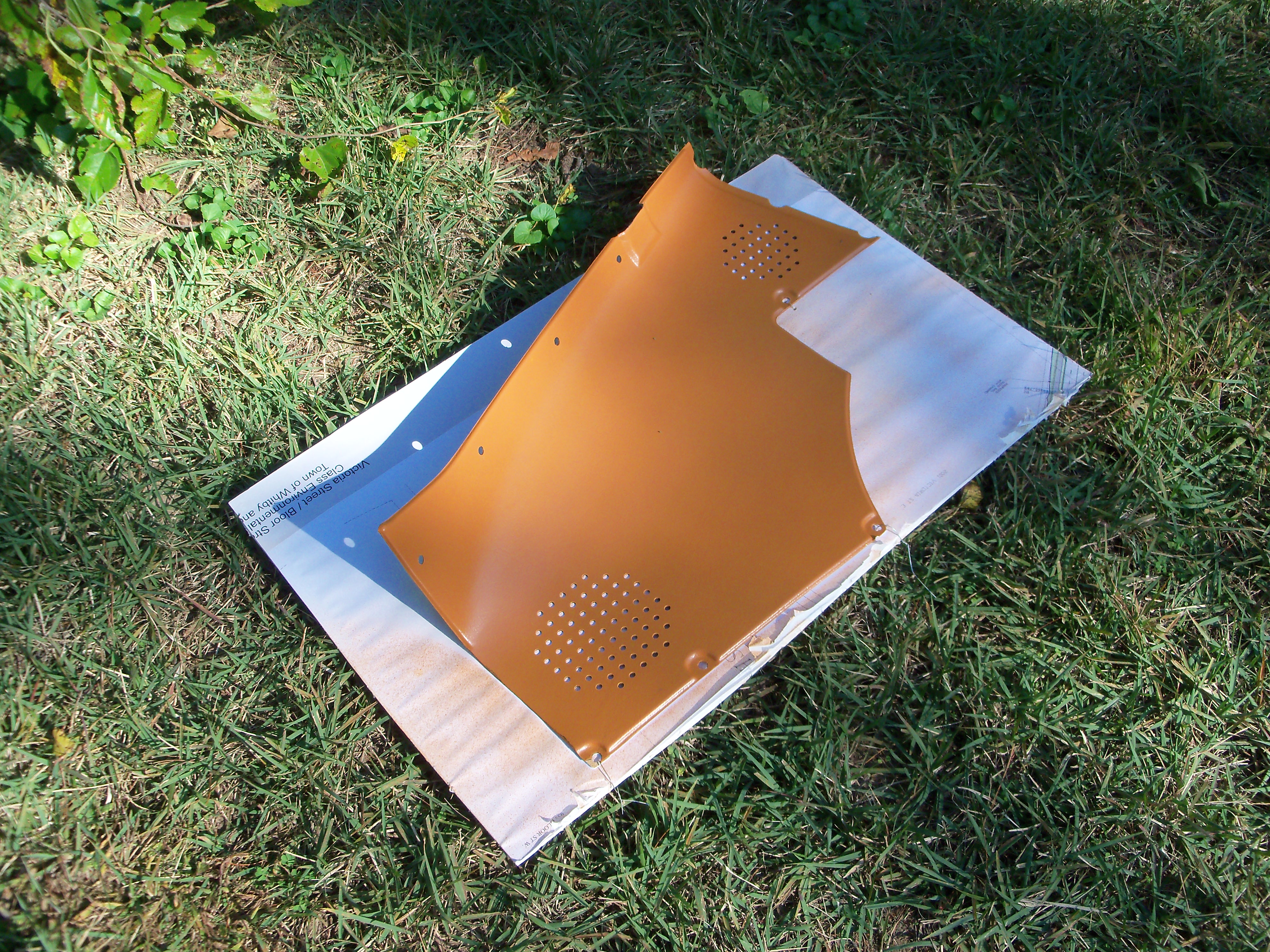
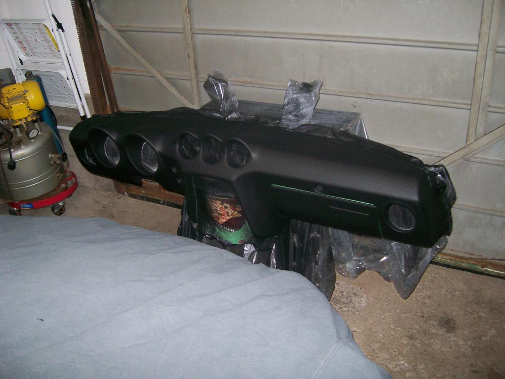
That looks very promising. I experimented with thin, flexible vinyl (stretchy fabric backing) for my dash project before deciding to go with textured paint. I found that the vinyl simply did not have enough formability to contour around and into the gauge recesses -- even in bright sunlight and assisted with a heat gun (see photo). Even if I'd been able to get it to form down fully into the recesses, it looked like there were going to be major wrinkles happening around the outsides of the pods. The Z dash has some very challenging contours! BTW, the vinyl I tried was the thinnest fabric-backed material I could find at the local fabric store. I did actually find a manufacturer that makes a textured vinyl with the exact 'haircell' design used by Nissan in the Z. It was 3-mil thickness IIRC. The manufacturer wouldn't answer my emails, so I gave up. That said, these new commercially-available automotive wraps are also only mils in thickness and they seem to have the ability to form around significant contour changes successfully. Not sure whether wrinkling around the gauge pods isn't still going to be a problem, though. And if my dash repair starts to show cracks (it hasn't, 2 years later), I think this stuff might be my next strategy. If you try it, be sure to post some pictures of the results.

-
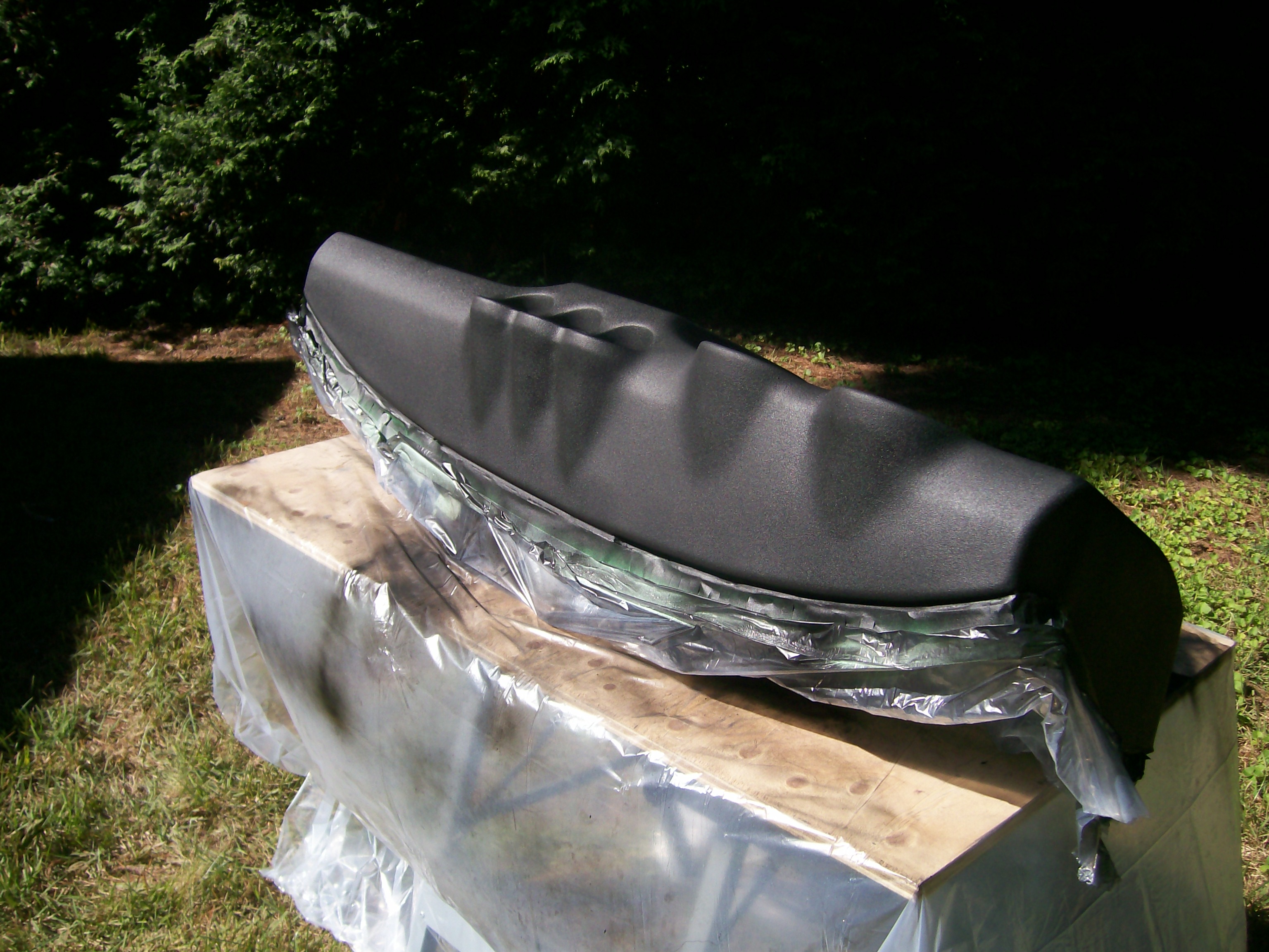
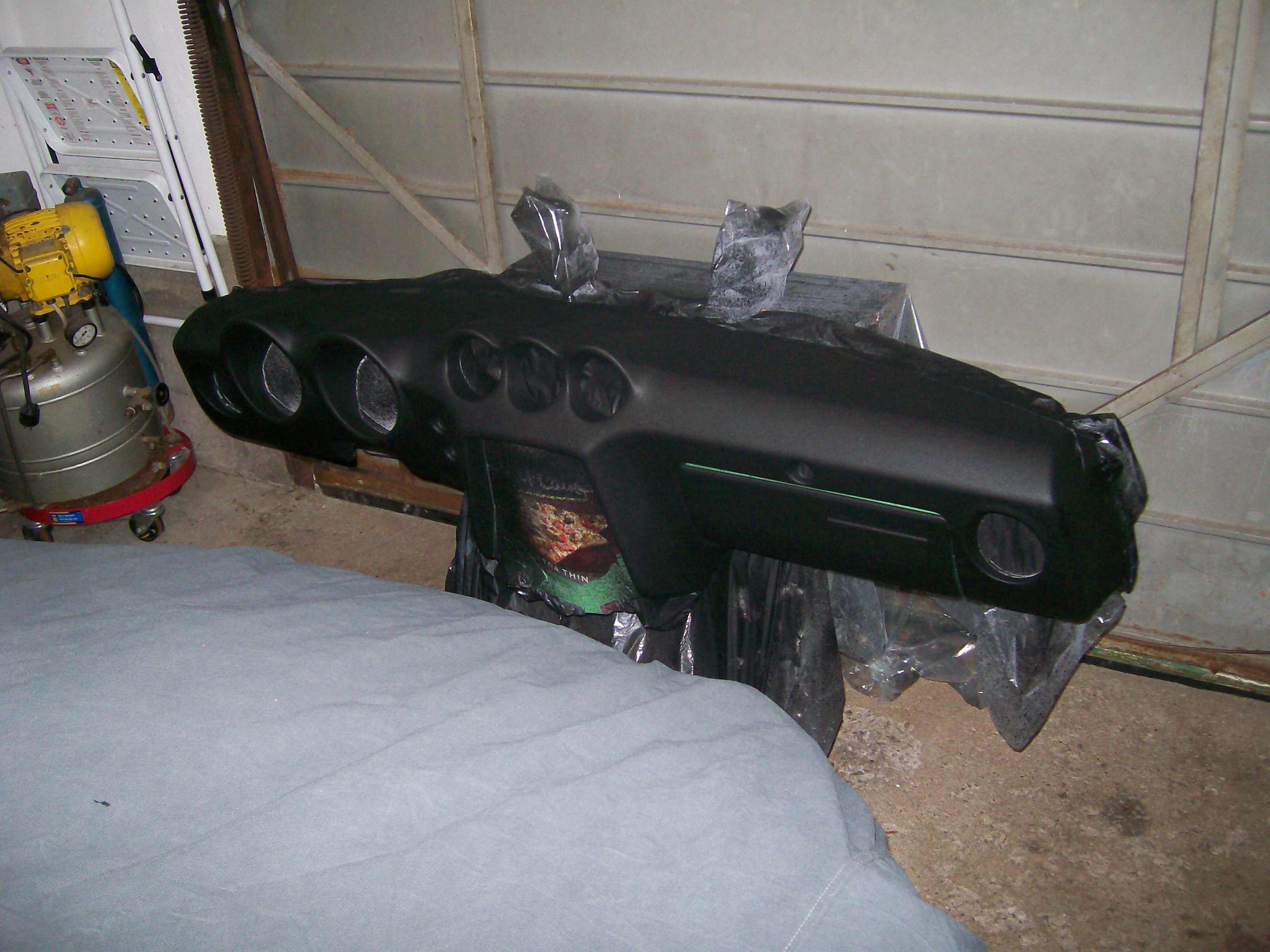
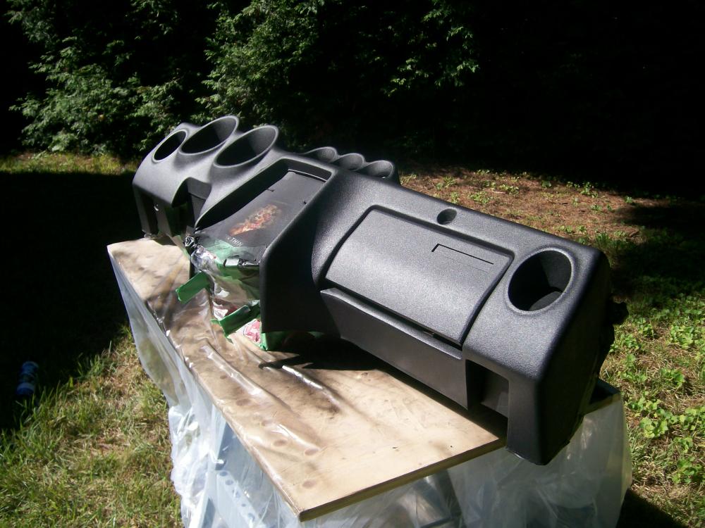
Re application tips: I refinished my dash with similar results. I'm happy with the outcome, even if the texture I ended up with isn't the same as the factory 'haircell'. Based on the pictures Chris has posted, the final appearance I got looks to be about the same. In my case, though, I used Dupli-Color's bedliner paint rather than the SEM texture product. I found one curious thing during the spray application that may help others who try this repair-and-paint process with their own dash: The bedliner/textured paint tends to start 'spitting' out of the spray can, no matter how much you keep it shook up nor how well you keep the spray tip clear. The result is 'blobs' of wet paint that appear to have ruined the finish. Out of desperation, I tried lightly touching one of those surface blobs with my fingertip to see if maybe it could be smoothed out. The result surprised me. Just that light touch settled the blob right out. I don't understand the mechanics, but the action was self-evident. I ended up making this a standard part of my spray-application routine with this kind of paint. The end result (three coats) was a nice uniform finish, with no 'blob residue' in evidence. I covered the bedliner paint with a finish coat of SEM's 'Landau Black' to make the surface feel a little harder/smoother to the touch (the bedliner paint feels a little 'grippy'). If you decide to try one of these texturized paints, I recommend you experiment on a big piece of cardboard before you start on the actual dash. In my case, I had a spare glovebox lid to play with. You may also want to experiment with the different texture paints that are available to which one you like the best. A difficult aspect of the paint application is getting coverage inside the instrument pods without accidentally over-applying to the surrounding areas. Takes some practice and forethought to avoid problems. BTW, I found that my B&D 'Workmate' folding bench was perfect for mounting the dash during both the crack-filling and the paint-application steps (see picture #3). Note the big C-clamps used to clamp the sheet-metal armature of the dash to the top of the bench.

-
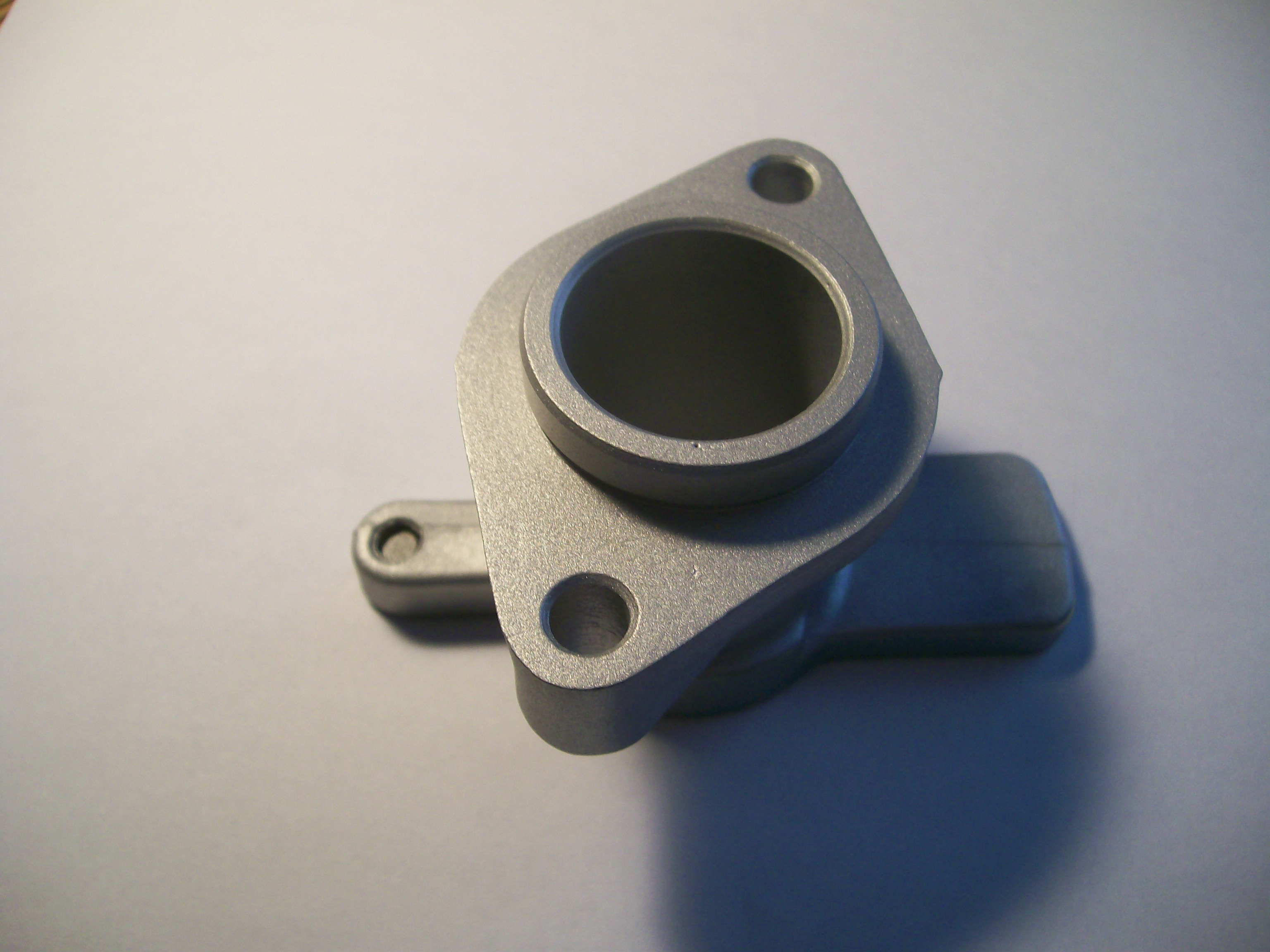
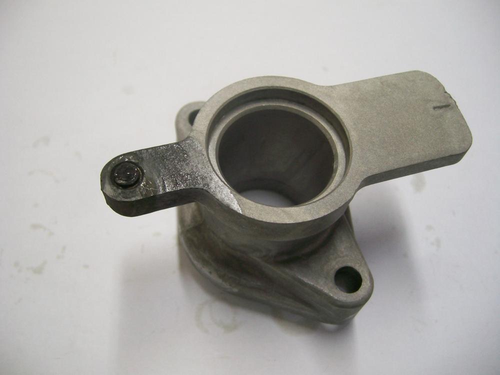
Sorry, but those are pix of the same part. Just turned upside down in the 'after' shot. No way I was going to leave this part in this solution any longer than I did. Too much action happening on the aluminum surfaces and I didn't want to damage the machine bore. In any case, my experiment wasn't really about fixing this part. Instead, I wanted to see whether this technique had any promise for getting the snapped-off manifold stud out of my car's cylinder head. The distributor casting was just a guinea pig. I just had lunch with my my friend the chemical engineering prof earlier this week, but we talked mostly about my zinc electroplating set-up and I forgot to ask about this other process. If I pick up any insights in a future conversation, I'll let you know.
-
and once again we head down the rabbit hole...
-
I had high hopes for this treatment but -- like many things that appear too good to be true -- I can now report that, after trying it out, this whole thing is 100% bogus. My test piece was a spare distributor base casting, complete with the remnants of the snapped-off locking screw. I bought a small can of alum off the grocery store's cooking spices shelf and then dumped it into a small saucepan full of water. After bringing the water up to just below boiling temperature, I dropped the casting in to see what would happen. There was a lot of bubbling action, although it all seemed to be coming off the aluminum surfaces rather than from the area of the snapped-off screw. After watching this for about a minute, I started to get concerned that the process was attacking the wrong metal (i.e. the aluminum, and not the steel). I re-jigged the casting so that only the 'ear' with the screw shank was immersed in the water, and then let things go for about 20 minutes. There was still no sign of anything really important happening around the steel screw. After the twenty minutes were up, I pulled the part out of the water to inspect it more closely. As you'll see from the 'before' and 'after' pictures below, my suspicions were correct. The aluminum had been eroded (you can see the etching lines from where the water surface was located). The exposed surfaces of the screw shank were darkened, but that's about it. I still had hopes that maybe the chemical action had attacked the corrosion between the screw threads and the casting threads, so I took it down to my workbench to see if the screw was perhaps now loose (or, at least, not as frozen as before). Nothing doing. It still wouldn't budge, and now I'm back to having to drill it out and re-tap the hole. In addition, the 20 minutes of full immersion had 'pickled' the rest of the aluminum casting's surface, making it darker and -- well -- not as nice as it looked at the start, fresh out of the blasting cabinet. End result: Perfect alloy casting is now not so perfect any more, and the snapped-off screw is still firmly stuck in place. Conclusion: Don't waste your time on this 'miracle cure'. It doesn't work and it will eat your aluminum parts.

-
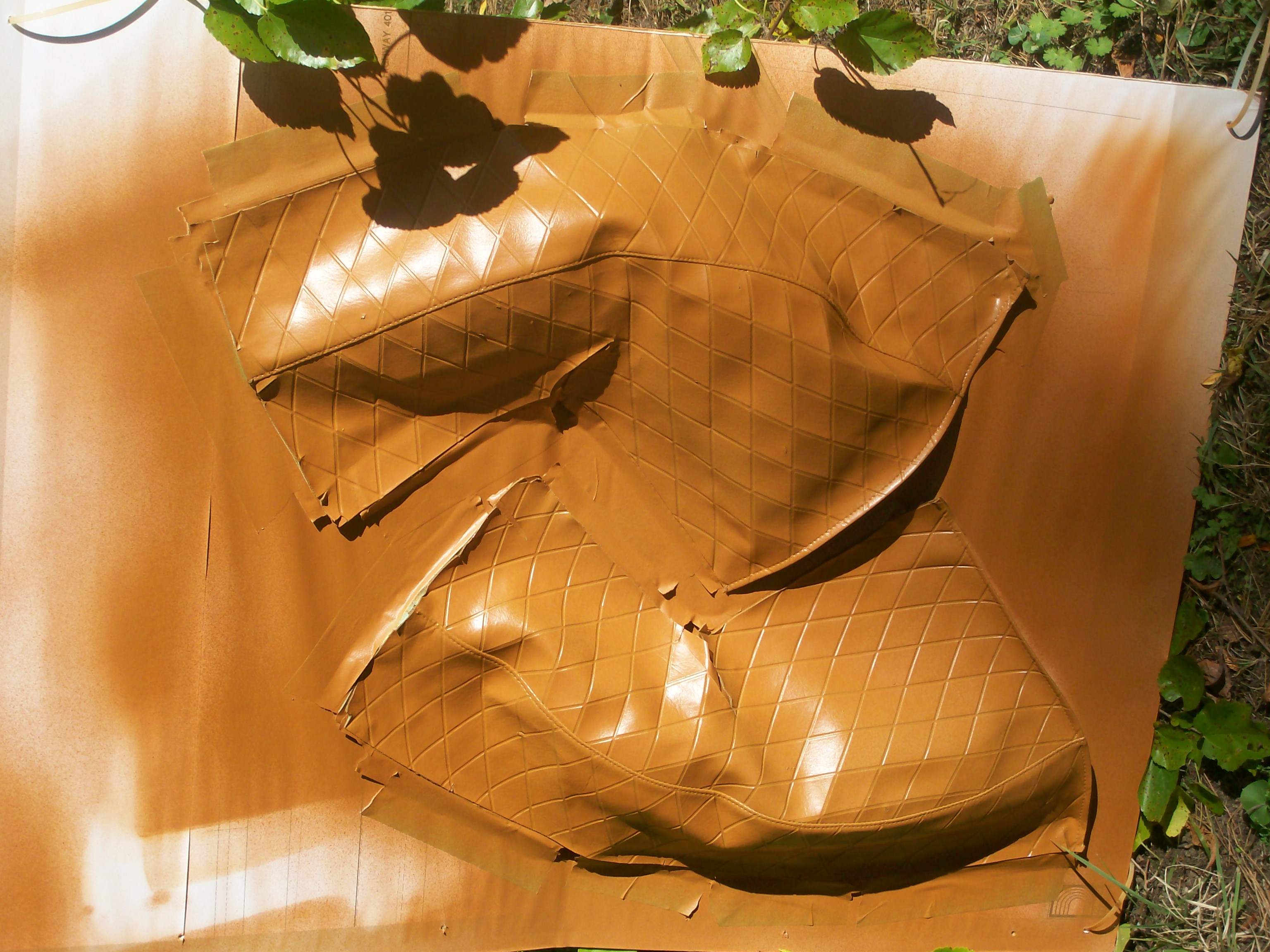
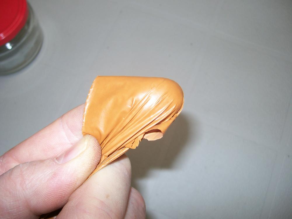
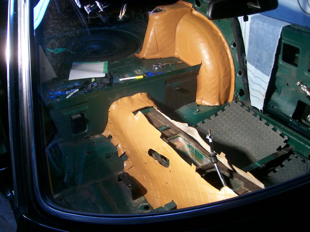
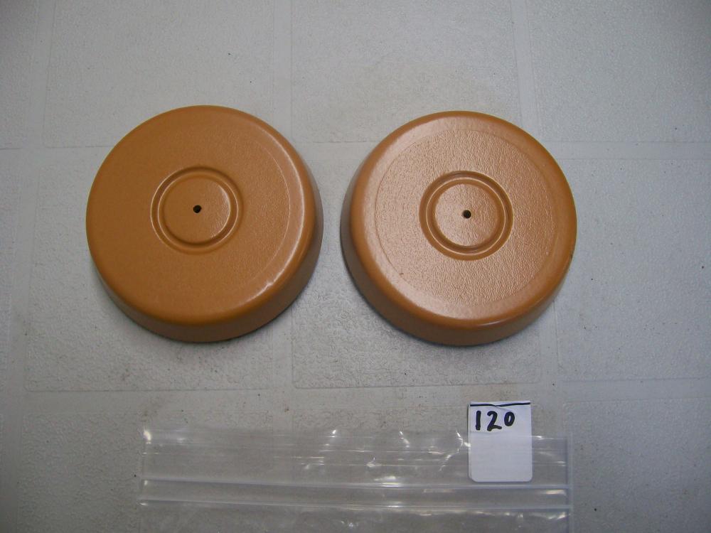
Hi Chris: You've seen my Z's interior panels, treated with spray-on 'vinyl dye' that I sourced from Parasol in Toronto. Here's a picture (#1 of 5) I took of some oversprayed material that I peeled off a test surface. It should give everyone a sense of the thickness and consistency of the 'dye' material after it's cured. As you can see, it's not really a dye at all, but more like a flexible-vinyl coating. I have zero concerns about its adhesion to the hard plastic parts, and the coverage (butterscotch dye applied over black plastic) was excellent. A bonus was that Parasol were able to color-match the dye to my new (Banzai Motorsports) butterscotch seat covers (thank you, Mike). The soft vinyl parts were a bit trickier, due to the challenges of fully removing years of ArmorAll applications. It took a lot of scrubbing with a scotchbrite pad and SEM's vinyl cleaner product to get these pieces ready for painting. For the most part, I'm happy with the end result (once again, butterscotch applied over black) and I do not foresee any application-related lifting or peeling problems. I would not recommend vinyl dye treatment for seat covers, though. That's just asking for trouble. As for resistance to scuffing and scraping (esp. in the cargo area), I think the first picture tells the story (i.e. it probably will tear if it's abused).


-
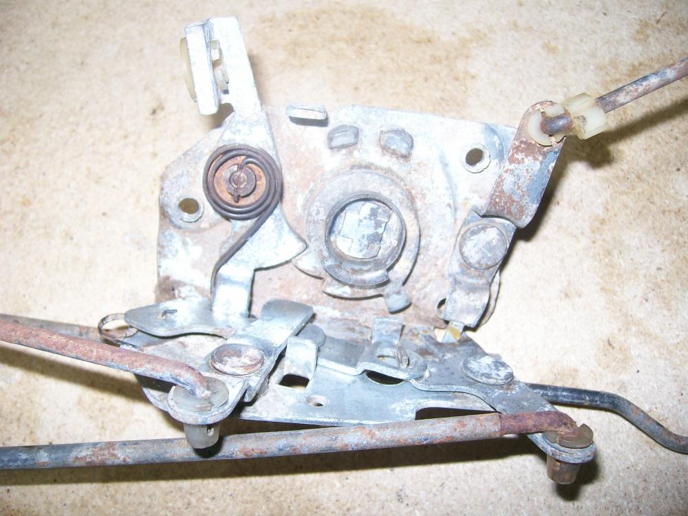
The Latch works on a kind of ratcheting principle. Hard to visualize until you play with one that's been removed from the door. If you get it cocked into the 'latched' position, you should be able to get it to release by pulling on the inside door handle. The hidden workings of the Lock (i.e. on the other side of door, per your photo) can get pretty gummed up and rusty, so getting lubricant in there is a lot more helpful than trying to oil from the outside (which only addresses one of the many moving parts in the assembly).
-
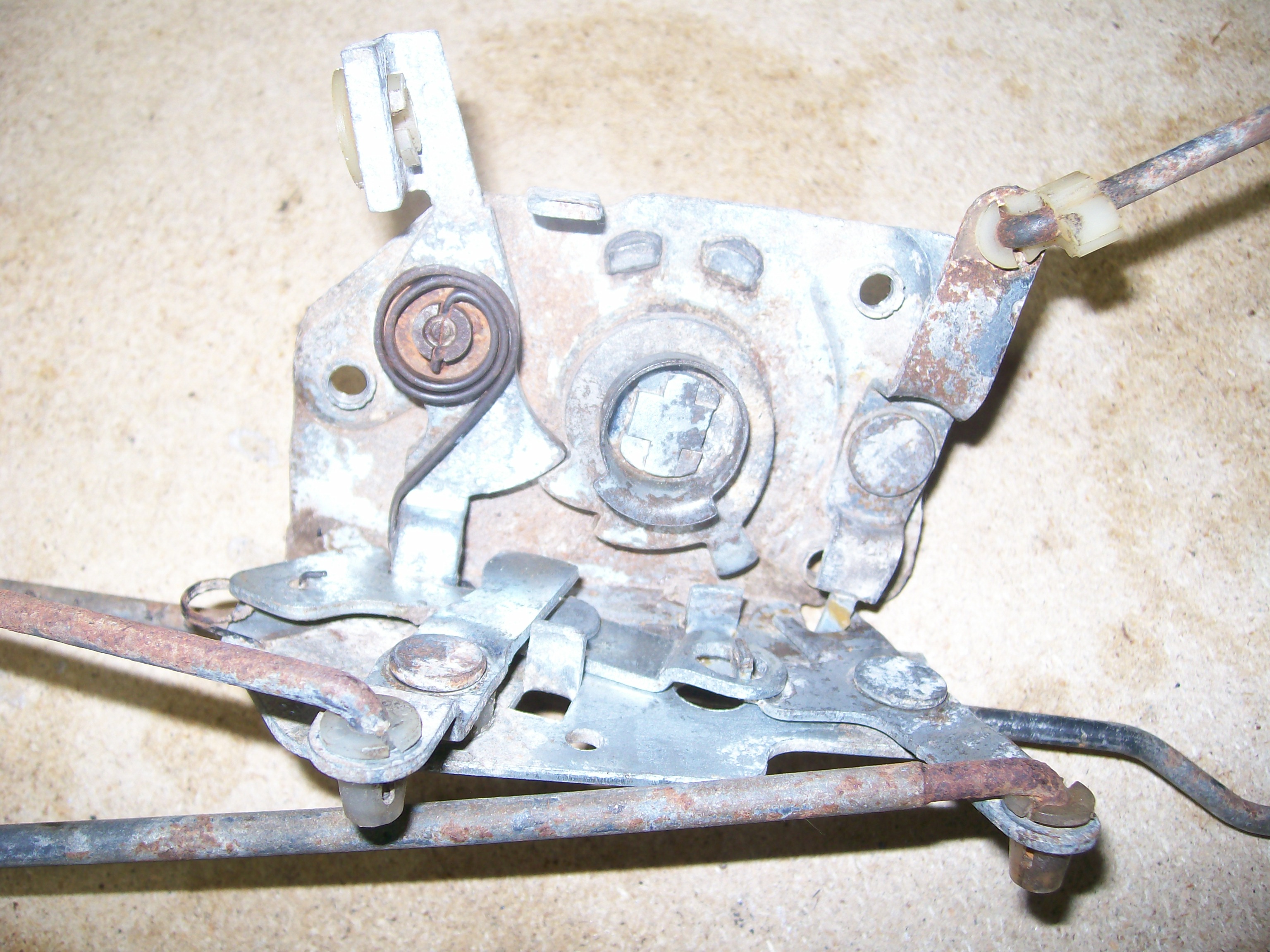
That is the 'Assy-Lock Door LH' (Nissan PN 80501-E4100). You can't see most of it in the photo, because it's on the other side of the door panel. The part of the Lock Assy that you can see from the outside (per your photo) is sometimes referred to as the Latch. The little plate below it is called a Dovetail. Shouldn't be hard to find a replacement Lock Assy. Unfortunately, they come equipped with lock/latch control rods that are very hard to disassemble from the actual Lock unit, so you'll probably need to buy one as a complete unit. Z Car Source of of Arizona offer them for about $225 (used). I suspect that somebody on this site might be willing to offer you one for a lot less. Yours can probably be fixed, though. In fact, it may not need fixing at all. Instead, your Striker Plate (the part on the door jamb) may be mis-aligned, in which case the door won't latch closed properly. There are some very good write-ups on this site for how to carry out the lock/latch/striker alignment process. The best one, IIRC, was done by our late friend EScanlon. In addition, I see that at least one of the two engagement lobes on your latch has lost its rubber cover. It's been documented by others that this apparently minor reduction to the outside dimensions of the lobe can cause the door to not latch properly. You can buy new rubber covers inexpensively from Steve at www.240zrubberparts.com. I also see that someone has replaced one of the mounting screws for your Lock assembly with a slot-head screw. It should, instead, be a stubby countersunk machine screw (like the two used on the bottom of the Lock, and also on the Dovetail. Of the three csk machine screws used to mount the Lock to the door, two are 12mm long while the third is only 10mm long. IIRC, the 10mm screw belongs in the lower inboard hole. If one of the long, 12mm screws finds its way into that hole, it can block the Lock's action. Check this on your Lock, just to be sure. If necessary, you can steal one of the mounting screws from the Dovetail (which are also the short, 10mm variety -- or, at least, they should be). A bent control rod (inside the door) may cause problems of a different kind -- either with locking (via the lock button), or with unlatching (via the inside door handle). A control rod that's fallen out of its socket could cause similar problems. You'll need a new plastic socket insert to fix this. Lubrication of the lock assembly might be possible without taking the door apart, but you're going to need a very long spray wand to get the lubricant into the right places (lubricating from the outside, per your photo, will only accomplish 20% of the job). A good-quality penetrating oil will probably be a better bet than WD-40. You'll probably need to pull the interior door trim panel off to do this job properly (be careful -- these panels are expen$ive to replace and they're easy to break if you don't use care and a proper trim removal tool). If you need to replace or fix any of the innards of the lock assembly, you may need to take the door apart. Read and follow the procedures in the FSM. I suggest you start by replacing the rubber pieces, checking the mounting screws, doing a visual check of the internal control rods, and lubing the Lock assy (from the inside). Then do a check on the Lock's latching action by exercising it with the door handles and the lock push button. Make sure the latch/lobe piece is rotating and releasing freely. If all looks good, get the latch back to its neutral position and then try closing the door. If there's still a problem, it'll be time to check the adjustment of the striker plate. It will probably help if you can describe exactly how it is that your door, 'doesn't close'.
-
I've asked this question before and never got what I thought was a satisfactory explanation. Maybe you know: Why are the rubber dampers mounted on a spring-loaded pivot? If they're designed to pivot, why does the spring loading act in what seems to be the wrong direction (i.e. the spring loads the damper against the striker plate, while the metal tang on the damper's metal carrier stamping prevents the rubber damper from pivoting out from the striker plate)? It just seems wrong.
-
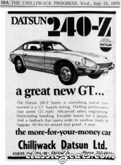 Great posting of a dealer ad from back in the day. There was a time when the pecking order for Japanese imports went like this: Honda Datsun (not Nissan) Toyota everybody else Now the pecking order (for all brands, not just Japanese) seems to be: Toyota everybody else
 -
What Jim said. The forty-year-old copper wiring will often be coated with a hard black tarnish. In fact, out of curiosity I completely stripped off all the insulation from one of my harness-to-headlight wires and found that the surface corrosion on the wire strands extended over pretty much the whole length of the wire. Doesn't impair the actual conductivity of the strands, but it will create high resistance at a mechanical connection (and it won't take solder, either). FWIW, I've had good results cleaning up the wire ends, pre-crimp, using a wire wheel (steel works faster than brass) in my Dremel rotary tool. Orient the wire wheel so that it spins along (rather than across) the wire strands.
-
Another vendor: Vintage Connections sells a pair of terminal removal tools (along with a full range of new terminals, shells, and crimping tools). The terminal removal tools work very well -- much better than any DIY solution I could come up with. Not expensive and highly recommended. Same for their crimping tool (and don't try to do this job with regular pliers -- the resulting mechanical and electrical connections be suspect and without a properly-formed crimp you won't be able to get the terminal to insert back into the plastic shell). As Chickenman says, it's better and easier to replace the old, corroded terminals than to try cleaning them up.
-
If you're interested in the history of the industry, 'Boss' Kettering's biography makes an interesting read. One other component of the capacitor story that adds uncertainty is the report that the foil-in-a-can designs used for automotive applications apparently have a shelf life and lose their effectiveness over time. So that shiny new replacement that's been sitting on a shelf in a warehouse or parts-store for years may no longer be 100% effective. Or so I've read.
-
As I understand it, the use of a capacitor (aka 'condensor') in points-type ignition systems is not dictated by tachometer issues -- although it can create them. The capacitor is there to store the electrical energy that's generated in the ignition coil's primary (12V) circuit when the points open and the electromagnetic field around the coil's windings begins to collapse. That collapsing electromagnetic field generates a reverse-direction current in the primary circuit -- a process called 'self-induction'. The capacitor is there to absorb this electrical energy. Without it, a heavy electric arc would occur across the separating/closing contact points, resulting in pitting and burning of the points surfaces. The capacitor dumps its stored energy back into the primary circuit when the points are actually closed. A nice side-benefit of the points capacitor is that it eliminates/reduces the 'noise' that the car's radio can pick up when points arcing takes place. I'm not sure whether that 'noise' is electric (travels in the wiring), electromagnetic (travels in the air), or a combination of both. Unfortunately, it appears that the cyclic energy storage/dumping action by the capacitor interferes with the ability of some electric tachometers to see a proper signal. You'd need an oscilloscope, I suppose, to be able to study the difference in the shape of the signal, with and without the points capacitor in place. Our absent friend, Blue, did a nice write-up a couple of years ago on how to swap a later-generation Z tach into an early car.
-
Not sure what wiring diagram you're looking at. None of the versions I've seen make a specific call-out of the wiring colours at the dimmer rheostat. It seems obvious that the wire on the right (in the wiring diagram) is RL, but the diagram leaves it for you to guess at the colour of the wire on the left. Anyway, the wiring on the rheostat from my '70 is intact. Both wires are RL. In your #1 photo, you have one wire intact, located at the 3:00 o'clock position. It has a male spade connector at its loose end. The one that's snapped off belongs on the terminal located at the 5:00 o'clock position. This one has a female spade connector at the loose end, c/w the usual clear plastic shield. Both wires are the same length. If you're going to try to fix your dimmer rather than jump it, you'll need to clean the wiper and resistor coil with De-Oxit. Then put a light smear of dieletric grease on the rubbing surface of the resistor coil. Finish with a tiny drop of light oil in the control shaft bushing and you should be good to go. Mine works ok, except for an annoying dead spot over the 30% - 50% part of the control range.
-
Bonzi Lon's comment about watchmakers using this technique got my attention, so I did a little internet searching and came up with a site dedicated to watchmakers. http://mb.nawcc.org/showthread.php?94417-Removing-broken-screws-with-Alum-bath&s=9a54a148536c988626245b769919efd8 Here's a good summary comment from one of their members: "Alum is pretty danged safe stuff, and one of the safer things to get steel out of brass or aluminum. In other uses, it's used in heavily-silted water to flocculate (clump) the silt so it'll settle, and it also disinfects the water somewhat. My uncle used it to treat his tan-colored well water way up in the Colorado Rockies; a few cupfuls of alum would clear up 350 gallons (over 1000 liters) in a couple of days. It made the water taste a bit funny-sweet, but was perfectly safe. It's also used to make pickles crisper. It's the active ingredient in a styptic stick (used to clot shaving nicks). As people have said before, it works far faster at removing steel leftovers if it's hot. (WARNING! Don't use a steel pan or can to do this in - it'll eat that, too! Stainless isn't as reactive, but just use glass (Pyrex or its equivalent) or an aluminum pan, ok?) Bring some water to a simmer, and dissolve as much alum in it as will dissolve (saturated solution), toss in the brass or aluminum doohickey with the steel whatzis in it, leave it at or just below a simmer, and come back in "a while" to no more whatzis. It'll still work at room temperature (if you don't want a glass thing on a cooktop, always a valid concern), but it'll take longer (like overnight). The alum reacts with the iron, but not the aluminum or the brass. <geek> According to the chemistry book, it has to do with the trivalent nature of iron (which doesn't exist in copper or zinc). It starts out full of aluminum ions (which are also trivalent), so no reaction there. </geek> The stink is from the sulfates being ionized and released. If you inhaled enough of it, you'd eventually have a tiny fraction of the the sulfates bond with the water in your mucosal membranes to form a mild sulfuric acid, but your body will make you leave waaay before it comes close to doing any damage. In other words, don't stand and force yourself to snort the fumes, but don't break out the hazmat gear, either. Trust your nose to tell you when enough is enough. Use common sense." It's evident from the rest of the thread on that site that the alum technique is well known and proven effective -- at least, effective on tiny watch parts. A couple of commenters there speculate that it's especially effective on the threaded areas of a steel bolt -- and that may be true, although probably just because the liquid can penetrate along the threads, where it has a very large steel surface to work on (compared to just the head of the stud). In general, the watchmaker site commentary expresses full confidence in the safety of this technique for use with steel-in-bronze and steel-in-copper, but nobody steps right up and says they've used it successfully for steel-in-aluminum. We'll have to wait to see how it does on a a quarter-inch worth of snapped-off 6mm bolt in my aluminum casting.
-
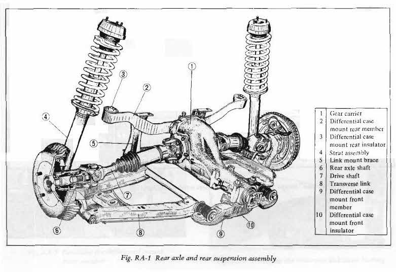
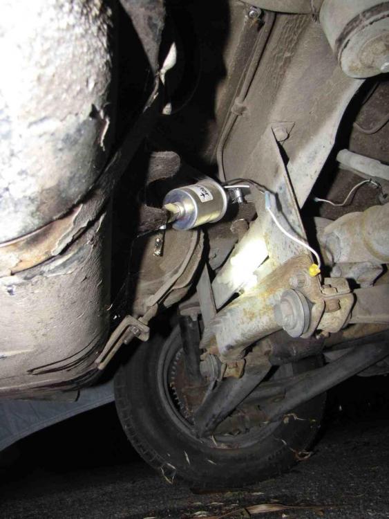
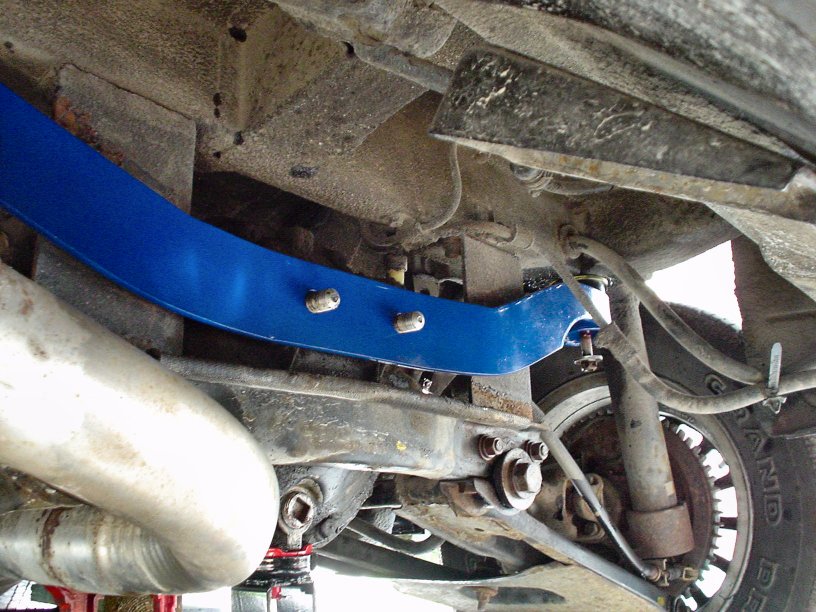
I've been looking at pictures and scratching my head over this. Maybe someone can solves the puzzle for me... I think everybody knows that the design of the S30's moustache bar (MB) was changed from the original 'flat' version to a new 'curved' version at the beginning of MY-72. This was part of the re-design done by Nissan to re-locate the diff further to the rear so that the halfshafts would no longer need to operate at a 5 degree fore-aft angle. The 71 and 72 FSM's both use the same diagram of the Diff/Rear Suspension (see below). It shows the MB mounted with its end loops sitting on the front side of the bar. The MB is shaped so that it 'droops' down from the body. That droop means that the MB can't be mounted 'upside down'. If you're going to flip it (for whatever reason), it only be 'flipped' around its vertical centre axis, so that the MB will now mount with its end loops sitting on the rear side of the bar. Note also that the diagram from the 72 FSM shows the MB sitting in front of the hanging vertical brackets for the lower diff crossmember. Now look at the smaller diagram, taken from the 75 (280Z) FSM. It shows the MB mounted so that end loops are positioned on the rear side of the bar. Why? What happened to the rest of the drivetrain design to force this change of mounting orientation for the MB? And is the MB for the 280Z a completely new design, or is it just the later-style MB from the 240Z, installed in a flipped orientation? Just to confuse things further, now have a look at the two photos I've imported from other threads. The one with the blue MB is Blue's old 280Z project car. The other one is believed to be a stock 72 240Z with the MB correctly mounted so that the end loops are on the front side of the bar. Can anyone confirm that this photo shows the correct MB orientation for a '72? So, why is it that Blue's car has the MB 'flipped' (compared to the diagram from the 75 FSM) and, as a consequence, now sitting behind the hanging vertical brackets? This would seem to result in the Diff being moved a lot further back than the factory had intended (by maybe an inch or more?), and maybe even contacting the lower suspension crossmember under certain circumstances. BTW, this isn't the only photo I've seen with the MB sitting behind the hanging suspension brackets. Did these owners make a mistake and put the MB back in the wrong way?... and I ask this with all due respect, because I make this kind of mistake all the time!

-
Outstanding video. Hoser gods Bob and Doug MacKenzie and Red Green would be proud! Since I brought this whole topic up in the first place, I may as well volunteer to take on the role of 'Test & Analysis Department' on behalf of everyone else. Here's what I plan to do over the next couple of days: I still have a snapped-off (steel) bolt that's firmly stuck in the (aluminum) housing of the Honda Civic wiper motor that I plan to install in my Z. That bolt has defied heat, shock, ATF/acetone and torque. And the thread length is only 1/2" or so! It simply will not budge. So: this will become my test piece for the alum/water/hydrogen peroxide treatment. I'll report back on Monday morning. Stay tuned. Later next week, I'm having lunch with a friend who has a PhD in chemical engineering. I'll ask for an explanation of the science (or lack thereof) behind exposing iron/steel/aluminum to alum/water/hydrogen peroxide. I hope this works out better than the experiment I tried with boiling lemon juice as a parts cleaner. What a mess that made! (Didn't work either)
-
An old friend worked in the metal-producer industry for his entire career, eventually rising to senior management. He told me that the auto industry decided to try out higher-impurity-level hot-rolled steel back in the early and mid-1970's and it backfired, big time. It seemed like all cars of that era -- not just Z's -- had issues. I remember a guy in my office who bought a brand-new full-size Chevrolet sedan, circa 1977. It had a very attractive dark green metallic paint job. A year later, a rust blotch about 1 in. in diameter appeared out of nowhere in the center of the driver's door. Pinto's, Vega's, FIAT's, TR-4's, Volvo's, Jensen's, Porsche's -- the list of rust buckets from that era is endless. Except for American Motors, that is. They ran their unibodies through an immersion tank filled with anti-corrosion primer (zinc?) before painting. Rust is triggered by localised galvanic (electrical) activity. Impurities in hot-rolled steel serve to set up exactly that kind of localized electrical cell (and poor-quality steel had a lot of those impurities built right in). If I remember my Chemistry properly, moisture (esp. with salt added) acts as the electrolyte. On exposed panels, the moisture evaporates before it has a chance to get things going. However, when you trap moisture in the seams between two panels that have been spot-welded together, you're off to the (rust) races. Even the spot-welding process seemed to aggravate the problem -- or, at least, in the cases where the steel sheet wasn't very good quality. Add a little salty seaside air (e.g. loading and unloading docks, deck-top storage on the ship) and it permeates right into those seams. If you look at photos of a typical, moderately-rusted Z after it's been lightly sand-blasted, you can see the darker corrosion areas that creep out from all of the seams. Scary. 'Rust never sleeps'. A wash with phosphoric acid ('Ospho', 'Rust Neutralizer', etc.) helps to neutralize this -- and, I believe, might even serve as a 'sacrificial' coating on top of the steel. Nowadays (after the industry finally figured out how to get paint adherence), we see one and even two-sided galvanized steel sheet used for body stampings. You rarely see rust on a modern car's body panels, except for upper-bodywork (roof, trunk, hood) where some manufacturers still used non-galvanized steel.
-
Guys on the back corners look awfully relaxed, compared to the guy at the front. I wonder if this photo has been, um, 'altered'?
-
-
There was an, "I'm leaving" message posted about a month ago by someone who might have been Blue (but he didn't come right out and say so). The poster said that he'd tired of the website's ad-tracking features, etc. -- and of the internet in general -- and was therefore checking out. It certainly sounded very Blue-like. If it was, it's our loss. He was a famously helpful contributor and seemed to be always willing to assist someone who had a problem with their Z (I think Hardway can vouch for that). He also invested what must have been an enormous number of hours in creating some of the best 'how-to' articles I've seen, covering a huge variety of jobs. I'd put him right up there with Enrique Scanlon and Carl Beck as top contributors.
-
@ CanTechZ - I had looked at exactly the same picture in the 70 sales brochure, but the image file that I was using wasn't high enough in resolution to let me zoom in on the back of the engine. Yours is, and I agree with your conclusion. At least, to an extent. Sales brochures are usually printed a long time before a new model actually hits the showroom floor, and the vehicles used for the shoots may or may not be 100% faithful to the final production version re the odd small detail. BTW, it was fun to see in that picture how those cloth-braided ho$es came pre-frayed from the factory! @ Zed Head - Once again, I had looked at the same picture -- this time on the Z-Therapy site The caption on the picture of the 70-71 intake manifold is misleading. It says, "1970-71 non-water heated", despite the fact that the coolant pipes for manifold heating are clearly visible. Of course, what Z-Therapy are really talking about is non-water-heated carburetors, not manifolds, and in that respect they are absolutely correct: the 1970-71 carbs are not water-heated because the water-heating cavities in the manifolds -- which are there -- are not ported out to the carb bodies. I think that your take on the evolution of the whole manifold/carb-heating system is probably right. It went in steps: first, the obvious/easiest step of heating the manifolds, then the fix-up via the addition of the thermostat, then the improvement by adding carb heating. We're still left with the question of when the Manifold Thermostat was added to the design (and neither CarPartsManual.com nor the FSM's nor the TSB's seem to offer a definitive answer). Was it added on the fly at some point during 70-71 production, or did it arrive in conjunction with the carb heating feature in 72? Maybe Chickenman, c/o his Nissan Service background, has the answer...
-
Picture of front brake assy would seem to answer the plating question asked by Careless re yellow-zinc vs. plain-zinc for the calipers.