Namerow
Free Member
-
Joined
-
Last visited
Everything posted by Namerow
-
 According to the Caswell folks, the orangey-yellow-green irridescent appearance requires a two-step process: 1) dip in blue chromate, followed by; 2) dip in yellow chromate. It worked for me. Actually, I'm kind of partial to the appearance that the blue chromate creates all on its own -- but that's just me. Sorry, I don't have any photos of a part going through the various stages. I just have photos of 'after'. BTW, I tried finishing a part by bypassing the zinc plating altogether and just dipping the part in the yellow chromate bath. It was an unhappy result. The chromate didn't spread evenly across the part's surface. And it didn't adhere very well either. Even after letting the p[art dry for a day, I could wipe the chromate off with a rag. Do not use sugar (or corn syrup) as a brightener. No matter what you read on the internet, it will probably just poison your electrolyte. And it doesn't work. Just pay Mr. Ca$well the money. I have no idea what's in the little bottle they sell, but it sure made a difference for my plating results. Dull grey finish before adding. Shiny silver finish after. Of course, I have no idea what you're using for your electrolyte bath. If it's not based on Caswell's chemicals, then their brightener may not work for you. BTW, I wasted several weekends playing around with a DIY electrolyte made from vinegar and epsom salts. It really didn't work very well, despite meticulous parts cleaning beforehand. So much for all the promising pictures shown by others in their web articles. After a lot of time spent fooling around with plating, I've come to the conclusion that a healthy dose of luck or good karma is required. If you are able to generate good results, I'm happy for you. But if I had it all to do over again, I think I'd just go with a commercial plating shop.
 -
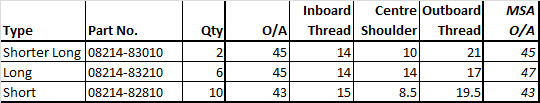
These are the length measurements I've taken (by eye, using a metric ruler) for the Nissan OE studs that came out of my 70 Z's head. The overall length for the studs supplied in MSA's kit is shown on the right... The Nissan OE studs are ground flat on the inboard end (the end that goes into the head), whereas the MSA studs aren't. You can see this in my photos. My 'thread' and 'shoulder' length measurements should be considered +/- 0.5mm, because it's kind of difficult to decide where the threaded-to-unthreaded boundary occurs.
-
I'll measure and post later today.
-
Might be worth getting the long through-bolts re-plated. They like to rust.
-
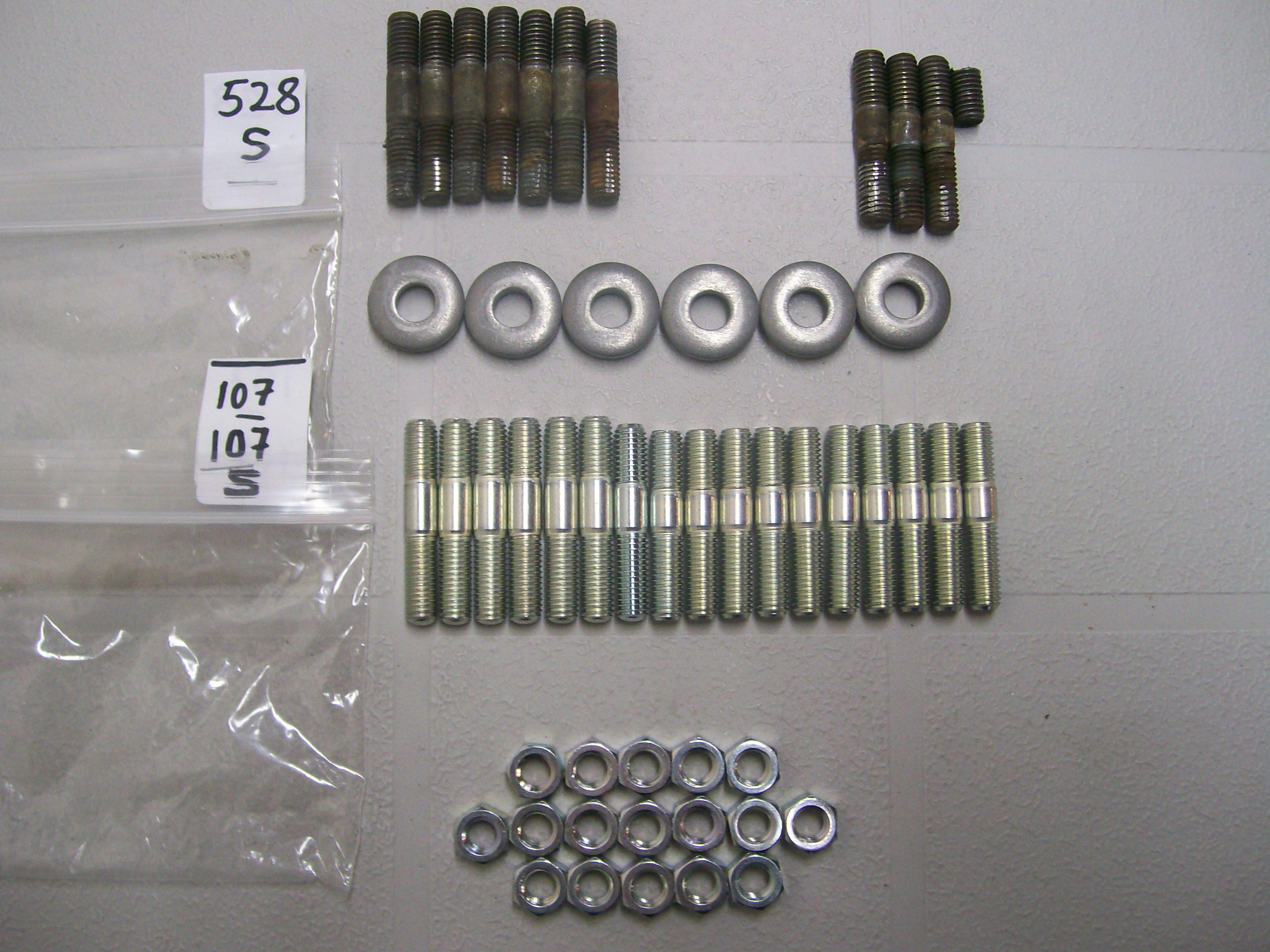
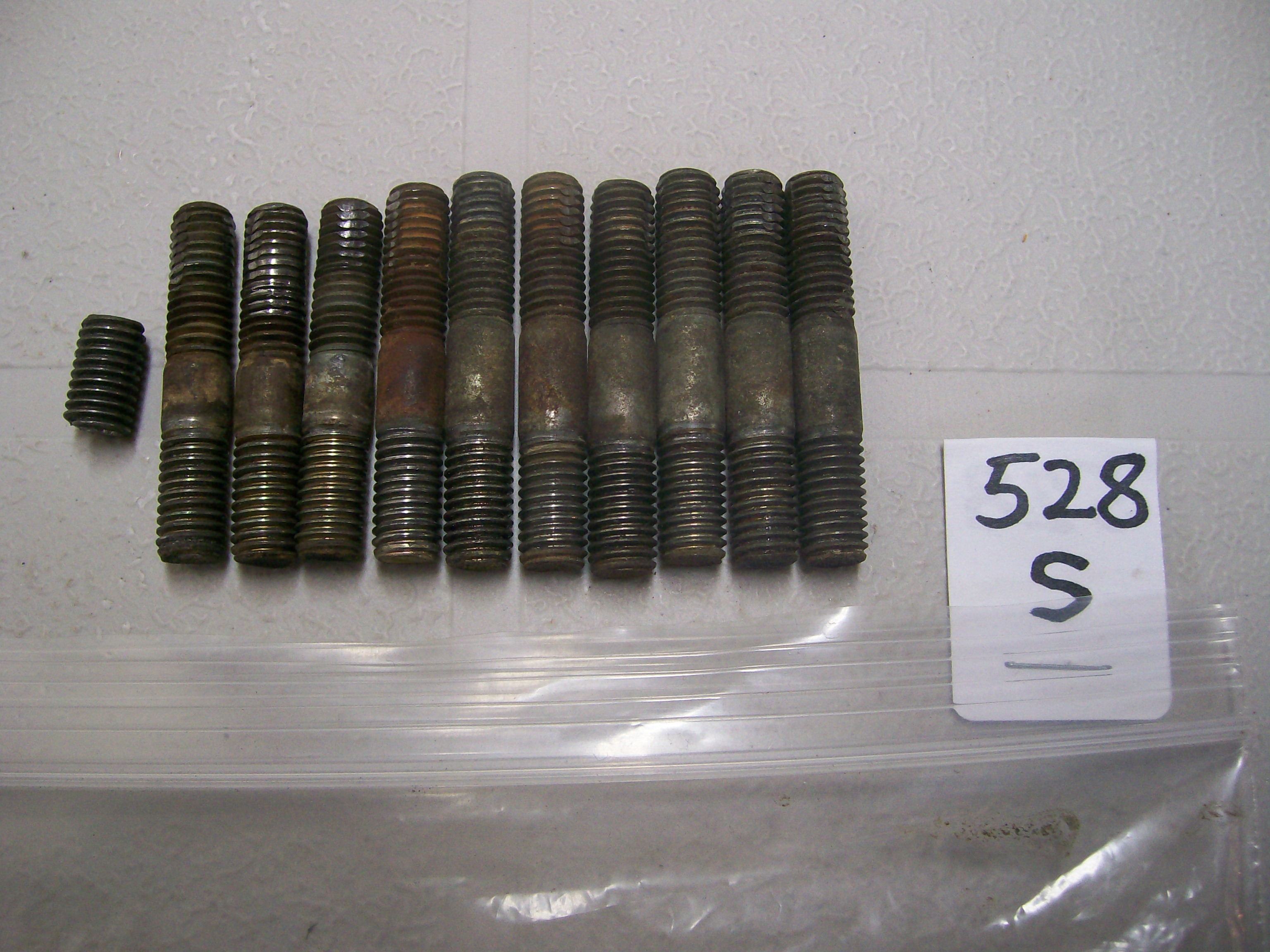
The manifolds are secured by a total of 17 studs (or 11 studs and 6 bolts, depending on which camp you want to be in). The Parts Manual lists them all as studs, but under 3 different PN's (with the related locations vaguely identified in the exploded-view diagram: Type ‘12’ – 08214-82810 - 10 of (short) - includes the top-most row, where my engines have bolts rather than studs. Type ‘13’ – 08214-83010 - 2 of ('shorter long') - one of these is clearly located in the diagram as the rearmost stud where the rear engine 'slinger' (hoist) plate is secured. Type ‘14’ – 08214-83210 - 6 of (long) - used in the locations where the thick 'yoke' washers are used to bridge the flanges of the intake and exhaust manifolds. Notice how the Parts Manual says there are 18 studs. In fact, there are only 17 studs used to secure the manifolds. I'm assuming that one of the Type '13's is used somewhere else. Here's the kit that MSA sells (my original studs are at the top of the photo): Notice the oddball silver stud (the one in the centre - no yellow zinc plating, different overall length from all the others, different length of unthreaded shoulder from all the others. Here's a closer view of my original studs (the snapped-off stud came out of the engine slinger plate location, natch)... A couple of observations: They all have the same threaded length for the end that screws into the head (makes sense, but easy to overlook during re-assembly). The threaded length for the 'engine' end is shorter than that for the 'nut' end, which means that I've got the studs stacked wrong-side up in my photo of the MSA studs. Once again, one of the 'long' studs is a little shorter than the others and has a slightly shorter unthreaded shoulder. In this case I know it was not from the engine slinger location, but unfortunately, I didn't notice the difference in the long studs until I had them all out on the workbench afterwards, so I can't be sure where it came from. It's possible that my snapped-off stud was also a 'short long' type, meaning that these are supposed to be fitted to both the rear-most and the front-most locations. If that's the case, then the MSA kit is technically incorrect by supplying only one of them. I don't think it's going to matter much for the front-most location, but I'm going to definitely fit my single 'short long' stud at the rear-most location to secure the slinger plate (I have a suspicion that it's made from a higher-strength grade of steel than that used for the plated studs). Comments welcomed from any of our veteran or professional L-Series engine rebuilders.


-
That does it! I'm putting the bolts back in the top row. Anybody want to buy six brand-new, never-used MSA studs?
-
Interesting. We now have a statistical population of two. Anyone else with bolts on the top row? BTW, a quick bit of on-line research suggests that studs are preferred over bolts in heavy-duty applications because clamping force is generated without any twisting of the fastener. With a bolt, the clamping force can deteriorate under high, cyclic loads as the bolt loses that twist. It's said that this is important for a cylinder head on a high-boost or high-compression engine working under heavy loads. However, I don't see how it would apply to the case of the Z's intake/exhaust manifold duty cycle. It was pointed out that studs create a different issue. They can be problematic for engine installation and maintenance procedures, because the clamped part (the manifolds in this case) needs enough clearance above/next to it to let the part be lifted over the studs during installation or removal. Unless I've forgotten something, I don't see that being an issue for the L-Series manifolds. So, I'm still puzzled by the apparently intentional mixture of bolts (top row) and studs (all the rest). Hard to believe it would have to do with saving costs (a stud set-up requires 3 parts, a bolt only 2). And I don't see much difference between a bolt and a stud/nut when it comes to wrench access. Maybe somebody in Nissan's Purchasing Department accidentally ordered too many bolts for another application and the Manufacturing people identified the manifolds as a place to get rid of them.
-
"The engine costs €120,000 ($140,490)..." I'm out.
-
To get the right appearance, you're going to need blue chromate, too. And brightener. Lots of brightener. The Canadian Ca$well outlet offers the following: Blue chromate: C$32 (one is prob. enough) Yellow chromate: C$48 (you may need two of these for a large bath) Brightener: C$21 for 4 oz ("Add 1/2 teaspoons per 1.5 gal of plating solution. When plate becomes dull, add another 1/2 teaspoon.") BTW, 4 oz. = 24 tsp, so you may need 2 bottles Factor in tax and shipping, you're looking at about C$150 - 200. I assume you've got your electrolyte bath and zinc and power supply already.
-
Would that fit in a P1800?
-
BTW, 'I do this all the time', and, 'I don't understand why it's such a big deal' are not acceptable responses.
-
No more plating pictures, please, until you show pictures of your set-up and explain your process in detail.. Hurting my self-esteem.
-
I had similar concerns over what I saw with those fat white and white-red wires in my 3xxx 70 Z. Toasted, but not fried. The challenging part is that the wire is rock-hard for about a half-inch inboard from the the connector and there's really no excess wire to let you just lop off the offending section and crimp on a new connector. I've decided to just hold my nose and put in relays as 'triage'. Also, I extracted all of the fuse terminals, c/w wiring, out of my 70 Z's fuse block and re-installed them in a good-condition block salvaged from my old 72. It can be done. Great photos, BTW... but not pretty.
-
Yes. When I said, 'switch contact' I mean 'contact ring'. There is another 'switch contact', of course and that resides inside the Relay. If you cannot quickly locate an exact duplicate of the Horn Relay, why not substitute a standard relay (like the one that you can purchase from any automotive parts supplier)? Someone else here can hopefully guide you on the connections you will need to make. Otherwise, you can consult a local automotive electrical service shop. Also: Before you play with the Relay, be sure that good electrical connections are being made to the Horns at the front of the car. This includes both the POS and NEG connections for both Horns.
-
For the 1970 - 73 models, it should be located on the left-side kick panel, just under the dash ('left' as viewed looking forward). From my notes (copied from someone else's notes): Terminal markings and wire connections at the Relay: B = Battery >> Green/Red wire H = Horn >> Green wire S = Switch >> Green/Black wire The Green wire is the one that is switched internally in the Relay. The Green/Black wire connects back to the Horn Button on the steering wheel. It works by grounding the circuit*. The Green/Red wire supplies power from the battery via the Fuse Box (4th fuse down on the Left side, 10A). (* There is a contact ring located under the Horn button. A wire runs from the contact ring to the front of the steering wheel. When you push the horn button, the front ring makes contact with the steering column, completing the path to ground.) If I had to guess, your problem will be with the switch contacts in the Horn pad and not with the Relay. But you never know. The attached wiring diagram (in colour!) was created a few years back by a gentleman named Sully Ridout and contributed to this site. It's appropriate to the 1972 N. American models, so it may not be exactly right for a European Z (other member located in Europe can probably comment). However, it may help you to figure things out for the horn circuit at least. S30 Wiring Schematic - 72 240Z - Colour (by Sully Ridout).pdf
-
-
If you buy a remanufactured unit, inspect it carefully before you leave the store. At least one member here (Grannyknot) reported that his remanufactured MasterVac showed damage to some of the 'teeth' on the lip of the housing (probably from poor handling during disassembly at the rebuild shop), to the point where he had concerns about its vacuum integrity. I think one of the threaded studs was marginal, too.
-
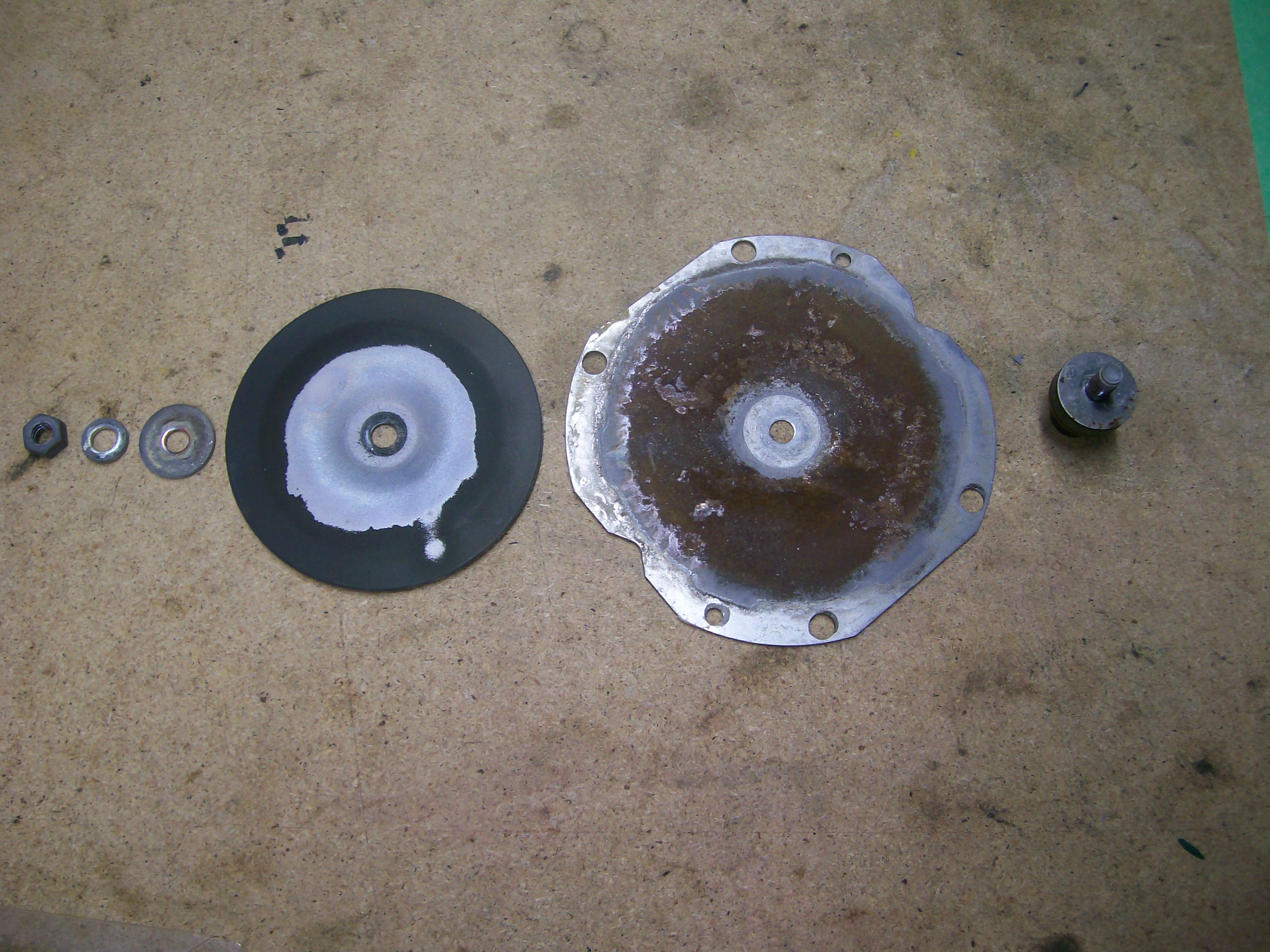
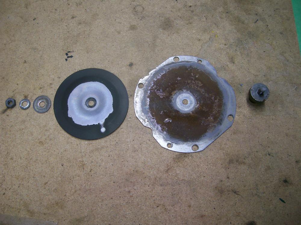
... or make your own gaskets. I made mine using butcher's paper. About the right thickness and somewhat waterproof. Zup's successful experience using no gaskets at all suggests that they contribute nothing to the acoustic performance, so maybe they were intended to be a moisture seal (albeit, not very effective -- see picture). So maybe a thin bead of silicone gasket material on each mating face would be the easiest and most effective solution. If, for any reason, the sealant snubs the sound output, you can always strip it off and try something else.
-
Serendipity, my friend. I remember the' authoratative' blast of my distinctly non-USA, two-tone Z horns delivered when I was a 1970's driver . When I rebuilt the horns from my 70 Z, I was shocked (as in underwhelmed) by what I heard. I love the nostalgia effect, but for the guerilla driving conditions where I now live, they need modern-tech, hi-volume reinforcement.
-
Not sure about this. I bench-tested my re-built horns independently, off the car, with direct pos and neg connections from a guaranteed 12VDC power supply. They had to be correctly adjusted with the adjustment screw. Move too far in either direction and 'bleat' became 'dink'... or silence.
-
I got mine (in 2015) from my local NAPA outlet. 6" canister, measured with my vernier caliper. Might have just got lucky, but don't overlook the obvious.
-
I hate anecdotal evidence, but I will say again that the variable with the most pronounced effect in my plating experience was the regular addition of of the Caswell 'brightener' liquid to my electrolyte bath. I don't know why. I have no formula or explanation to offer. Alchemy! Sorcery! I too want a Caswell franchise where I can sell overpriced, unexplained chemicals to optimists just like me.
-
It would be best if the comparison testing was done on the same dyno. Otherwise, the (probably) small differences measured could have to do as much with dyno A vs. dyno B as they do with exhaust system X vs. exhaust system Y. I haven't looked at chassis dyno specs for a long time, but back in my day, the best chassis dynos that speedshops could afford were based on eddy-current absorber technology and IIRC the absolute accuracy was on the order of +/- 5% . Decent repeatability, but only so-so absolute accuracy. The automotive and fuels/lubricants industry R&D labs that I worked with used controllable DC machines, where the accuracy was +/- 0.5%. Those units cost anywhere from $500K to $1 Million. The low-end machines may be better than they used to be, but it's always best to be using the same measurement device if you're looking to detect small differences with confidence.
-
Agree with Grannyknot and Patcon. Maybe it's that clean northwest coastal air. Can I send you a box of my parts that still need plating?
-
If you play with the adjustment screw (X-type panhead machine screw at the 11:00 o'clock position in your picture of the rear face of your horn), you may find an easy solution to your problem. If not, no harm done and you can move on to the next step of your troubleshooting. The adjustment is a bit hair-triggered and requires a little patience to get it right. If your car's PO played with this and lacked patience, he might have just given up and left it in the 'dink' adjustment zone.