Mikes Z car
Free Member
-
Joined
-
Last visited
Everything posted by Mikes Z car
-
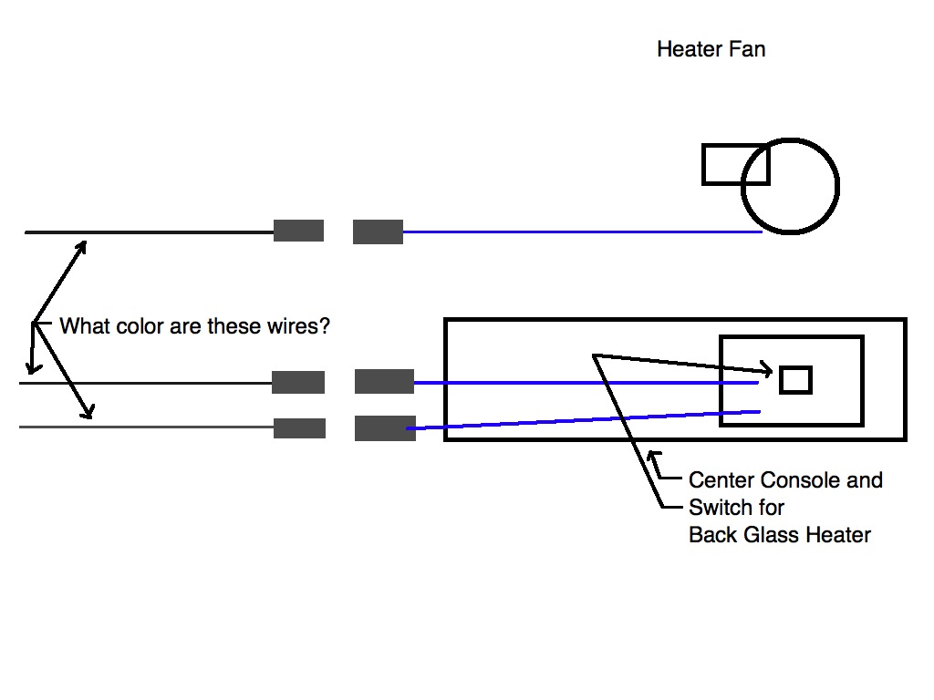
 Thanks to everyone for the great information. What I am trying to figure out is (see attached drawing for clarification): 1. What color and color stripe are the wire(s) that the heater fan plugs into? (one wire I assume) 2. What color and color stripe are the wires that the console switch plugs into? (two wires I assume) The PO did some great work on my car but I want to connect the wires more like stock and when I bought the car the blower could be turned on with the key removed and the back glass heater switch had no wires connected to it. Can the back glass heater be turned on with the key removed? Seems I remember on my old 71 240 that it could be and I was always worried about leaving it on. Thanks for any information, Mike
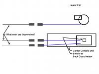
-
Hi all, The FSM for early (1/70) 240Zs doesn't seem to exist and the one for the 1972 model that is available seems to show the wiring to be different from the 1970 model. Is there an accurate wiring diagram for the early 1970 240Z? When I use the search it seems to be able to take only one word and if two are used it seems to use them each separately so that a search on "accurate wiring" turns up posts with either but not both words. Do I have this right? Thanks, Mike
-
I think of the Z as an art form in styling.
-
Arne, That site looks great I bookmarked it as well. FastWoman, Its funny I guess but I always liked the original Z fuse box because of the convenient location and the way it looks so I went to a lot of trouble to restore the one I have by resoldering all the connections even the crimped ones on the connectors. I didn't want to go away from being stock anymore than it already is that is why I tried to fix the connector. The fuse box resoldering I plan on putting on my blog. That is a good tip on making crimp connections. I tried to use a piece of metal for that with the connector repair but it wouldn't solder; hadn't thought of copper tubing. Mike
-
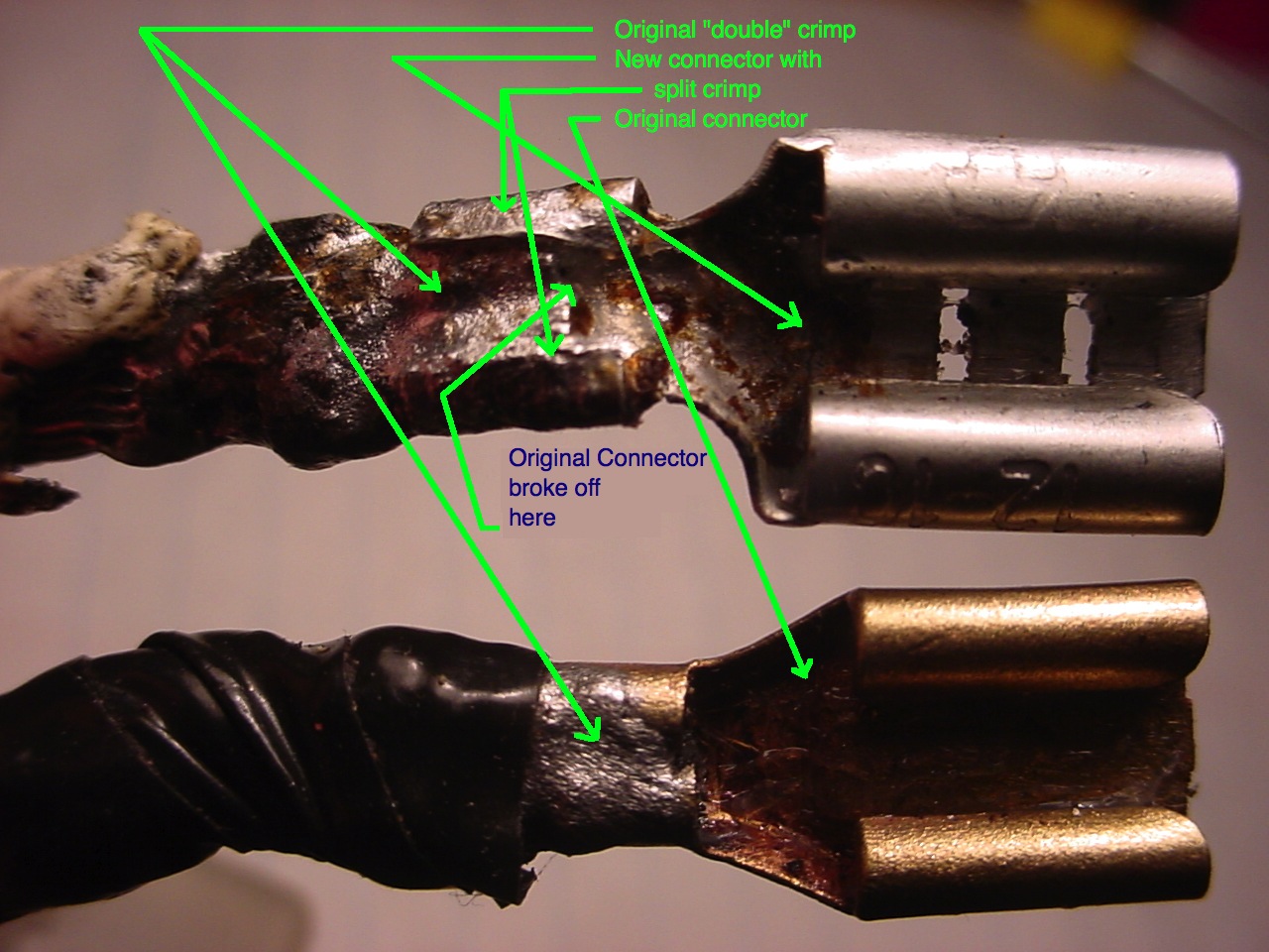
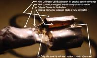
Thanks FastWoman, I listened to what you said and tried plugging in the connector to the car and finally noticed that the made in Taiwan new connector I got at the auto store had metal that was much too soft and was losing the grip on the spade connector it mates with. Running out of ideas I finally soldered in the original connector on top of the new one with the new one acting as a repair. The new rube goldberg connector plugs in great with a nice solid retention. Attached is a picture of the result though probably no one else will break this particular connector and get any use out of it! Thanks, Mike
-
Hi all, I want to replace one of the two very large connectors that are on the cable that goes out of the back of the fuse box because one of them broke off. These are the two white wires that go to the battery and ammeter according to the wiring diagram. I cut the crimp lengthwise on the largest connector I could find and tried to crimp it around the stump of the original connector that broke off. I soldered everything but someone who has raced cars told me that solder tends to come apart with vibration. Is there a way to get a really large crimp on connector to replace the original? I already tried Napa and another auto parts store and they just have 12 gauge crimp connectors like these. I need I think a crimp on connector for 10 or maybe 8 gauge from looking at it. Thanks for any ideas, Mike

-
I wonder what would happen if you temporarily hooked a wire from the radio chassis to a known good ground.
-
Scarab 155. I can't tell from the photos if it has the Scarab badging. Having never seen one personally I didn't know to look for that. Maybe they called it a scarab to garner attention and it really is just a 240Z with a 327 in it? I saw it listed in the paper here this morning and noticed the recent thread on Scarabs. Mikemerkury posted a much better picture; there may be clues there a better trained eye could spot. Maybe the size or shape of the Scarab badging can be discerned even if it can't be read. Mike
-
There is a Scarab coming up for auction here in Sun Valley in Idaho in early September. At least the advertisement was in the local paper and we have a Sun Valley here. Attached is a picture of the car (poor scan of newspaper print). It is a 72. I am not affiliated in any way remote or otherwise with the auction. Mike


-
Thank you for the great pictures
-
Hi all, I soldered both ends of all rivets and all wire crimps to fix fuse box overheating. Rivet and crimp location shown here: Other screenshots from drawing: Drawing: 240Z_fusebox_early_1970_final.skp.zip I pulled the fuse holders from the fuze box before soldering to prevent melting. Sanding or cleaning the fuse holders with copper cleaner and bending the fuse holder together to tighten the grip on the fuse also can help with overheating. You will need sketchup or sketchup viewer to look at the attached drawing which can be downloaded for free from Google. The drawing is 3D and can be zoomed in for details. It shows the inside/outside of the fusebox including the fuseholders, the colors of the wires and has text to indicate the destination for each wire. It also shows the cables that go out the back and the connectors on the end of the cable with all connections labeled. It is very close to being a scale drawing.
-
What is wrong with the car? I live in Boise but I don't know if I know enough to be of much help. Can you take pictures or video of any of the problems? The Z Doctor here in Boise near the intersection of Chinden and 43rd has done some excellent work on my car. He replaced the lowered springs the car had with stock ones and did some extensive carb work. Also he replaced the ignition coil and added a auto cutoff for the fuel pump since I was having some trouble with the way it ran. It runs great now.
-
This mod has been in my car for 5 years, works great. Before/After modification (click for animation): I noticed low gas gauge readings. When I looked at the sending unit in my 240Z gas tank I saw that it has a worn curved track across the coil of resistance wire where the copper float arm connector slides across the coil. The sending unit I have must be original gauging from the large amount of wear on the wire. Since the rest of the unit looked good I figured I could significantly increase the life of the sending unit by shortening the copper arm just enough so that the arm contact point slides over the wire on a different part of the wire where the wire is not worn at all. The steps I used for this were: 1. With the unit out of the tank and disconnected from the car, I measured the resistance at the two connectors that go to the car at max/min travel of the float arm. Mine was close to 8 and 90 ohms. I used this info when completed to verify proper operation. 2. I remove the protective flat cover over the coil that is held in place by three tabs. I straightened the one tab that is twisted after it goes through a small slot. Once it releases the other two will slide out. 3. I marked a small dot on the coil using a marks a lot or similar in line with the very end of the copper arm as it swung in both extremes of direction. 4. I loosened the set screw allowing the copper arm to swing over a wider range of motion than before. 5. I shortened the effective length of the copper arm by bending it up and then down so that it is shorter. It wound up looking like this: ________/\________ It was sticking up in the air at this point, this is how I fixed that. 6. I adjusted the pressure on the arm so it contacts the coil at a gentle but slightly firm pressure. The pressure can be adjusted by swinging the arm over the end of the assembly and pushing down to over extend it. I noted that the arm approached the coil at the same angle as before and that the new position of the contact point is now on new wire that had not been worn. 7. Using fine sandpaper I sanded the wire where the contactor will be contacting the wire to assure a good connection. Sanding with the wire is probably better as sanding across it like the arm swings might work the wires loose. 8. Proper pressure can be verified by using an ohmmeter on the two connector posts as the arm is slid by hand over the coil. I wanted to see a fairly smooth transition from about 8 to 90 ohms, readings outside of that can be fixed by what i did in step 9. 9. I swung the copper arm and the float so both are at the end of travel they would see at the full tank position. Full tank position for the float will have it at its extreme end of travel in the direction towards the end of the resistance wire that has a wire going to the car connector. Holding the float in that position I moved the copper arm that contacts the resistance wire so that it lined up with the dot at the end of the resitance wire nearest the float that I marked earlier. I retightened the setscrew firmly. I verified proper setscrew setting with an ohmmeter to verify I saw close to the same readings at max/min float positions I saw in step 1. Note that there are a couple of other mods to fix the sending unit, the links to those other two ideas are here: 1. I added a wire to improve grounding of copper arm. See: http://www.classiczcars.com/forums/showthread.php?t=35258&p=318623&viewfull=1#post318623 This is how I added the wire (loop the wire a bit to reduce mechanical stress on soldered connections so the wire doesn't break off): 2. Use crazy glue to hold down wires and prevent them from moving when the sliding contact rubs on them: Http://www.classiczcars.com/forums/showthread.php?t=35258&p=318628&viewfull=1#post318628
-
I admire you folks on this board. Not only am I learning things about my car I couldn't learn anywhere else but I am learning about ways of working with people. I find myself incorporating that latter item into my own personality as I think what is happening here is great!
-
If it is truly a flux capacitor I am going to put it in my time machine...
-
jwtaylor, Very good I didn't think of soldering there between the fuse holder and the bus bar, I will give that a try first, much easier than my idea. Unkle, It looks like the MSA 240Z replacement fuse box uses rivets? I guess even if it uses them and it is new it should work for some years. Almost feel I partially hijacked this thread, all due apologies to the thread starter, hope you have benefited from the info. Mike
-
I did notice there seems to be a connection on the gizmo that isn't being used but the wire is so small I can't tell for sure.
-
Please add me to the map for Boise Idaho. Anyplace in Boise is okay just avoid the penitentiary. Thanks!
-
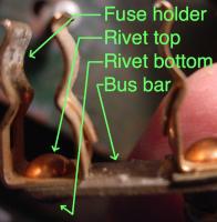
I went out to solder my fuse block to stop the melting of the fuse block (How did I get off on this? Aren't I working on rust prevention? But the fuse block was right there with everything removed, and while I was at it...) and I think I noticed what may be hiding here assuming I understand the discussion. I made the rash assumption that all one had to do was solder the rivet to the bus bar (see attached annotated picture -not sure I used the right terms) but on closer inspection (someone chime in if they see this differently) there are three connections here, the wire to the crimp, the crimp to the rivet and the rivet to the fuse holder as the rivet is a separate part. If I solder the rivet to the bus bar and the connection that is high resistance is between the rivet and the fuse holder I haven't accomplished anything. I notice others have put in separate inline fuses to bypass the hot connections to solve this. I may try soldering a 14 gauge wire from the fuse holder to the bus bar but that looks tricky to me due to the limited space.
-
My brake fuse has also melted the fuse block, not sure this is a recent thing just noticed it today. Elsewhere on this site I remember a solution of soldering the thing the wire is crimped to to the fuse holder after pulling the fuse holder out of the fuse block temporarily or something similar. The idea being corrosion between the two metals caused too much resistance and hence the heating.
-
Sorry, should be there now, I think I exceeded the max file size at first.
-
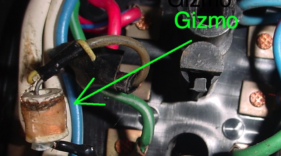
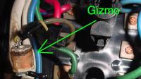
I found what looks like to me like a small coil of wire that could be a choke of some kind connected in the fuse box in series with the dome light circuit in my 70 240Z. It has electrician's tape on it so I don't think the factory put it there. From the attached picture can anyone tell me of what this could be? This is really winging it here but the only thing I can think of that might be connected is an auto arming alarm I used to have on a previous 240 that sensed voltage changes like when the dome light comes on, maybe the coil enhances a voltage change from inductive kick when the door is open to ensure the alarm is triggered? Thanks for any ideas. I plan on removing it and shorting it out if no one sees a reason not to.
-
I used a 4 lb sledgehammer on my drivers side frame rail to straighten it out some (responding here to an old post). Attached should be an animated GIF I made from a 7 minute video I took under the car looking down the frame rail toward the front while I used the sledge with a short 2X2 drift and then a four foot long one to get more swinging room for the hammer though I am not sure the longer drift helped any. The GIF doesn't show the many sledgehammer blows used to cause the straightening just the total result. Mike

-
My 71 240 got swiped from a covered parking lot at an apartment complex back in 82. The thief left it on the sidewalk at a college campus with the lights on and the door open. I had to get it from the tow yard. I got lucky, they must have used a key as there was no damage other than the battery had to be replaced soon due to being run all the way down I think. They swiped a jacket but it wasn't a good one. I changed all the locks with new ones and put in one of those automatically armed on exit alarms (don't know how effective they might be) and didn't have any more trouble. Mike
-
This is an old thread but in case anyone else runs across it I notice sketchup drawings are now available for the Z car. Google finds them with 240Z sketchup. There is a blue one and a red one, I don't know how they might be different other than color and I don't know if sketchup is considered cad. I can't edit either the blue or red one but I can add to them, I think that is because they were saved as models. Mike