Nissanman
Free Member
-
Joined
-
Last visited
Everything posted by Nissanman
-
 The TRAGIC part of this accident is that the convoy was, allegedly, allowed through a road block, into the inferno! Survivors and friends and family are not at all impressed:tapemouth
 -
The big red key is for a BATTERY ISOLATOR which is a requirement for racing. You'll definitely need that turned on to do any fault finding:nervous: It is probably best to connect the fuel pump power to some sort of safety switch if it isn't already. If the engine stops for whatever reason then power is cut to the fuel pump to avoid feeding a possible fire. Race cars usually have this fitted. It can take the form of a pressure switch attached to the engine oil gallery so that if the engine oil pressure drops suddenly, e.g. collision/rollover, then the fuel pump power is cut.
-
You are correct, the BR is primarily there to protect the 1.5ohm coil from meltdown when the engine is running. It was just something I noticed in the wiring diagram, removing the BR applied full voltage to both the coil and the tacho. As I mentioned above, for an impulse tacho. it may not matter at all.
-
My advice would be to avoid using lead filler, at all costs:finger: The health issues associated with lead working are too nasty to warrant using it. If you are comfortable with plastic filler then stick to that [pun intended]. You can convert a flat hole to a depressed hole with a ball pein hammer. It doesn't have to be very deep, only a mm or so. Back it up if possible with a small tube like a socket so that the depression doesn't spread too far. You can also apply a dob of filler behind the panel to give it a decent area of adhesion. Just prepare the hole like you always have, bare metal, scoured clean then apply the filler. Make sure you can paint the filler, front and rear, to prevent it from absorbing moisture.
-
If the tacho. is of the IMPULSE type then it shouldn't matter if the BR is removed. An impulse tacho. as the name implies, reads engine RPM by the number of impulses it receives on the primary ignition wire. The input is a simple wire loop that passes through a small transformer core at the rear of the instrument. If it works OK with the Pertronix conversion then it should continue to work OK without the BR.
-
Assuming that the push button is for the START power to the starter solenoid and the toggle switch is for IGNITION power, then to simulate the key being in the ON position just throw the toggle switch. No problem with it being wired this way barring security:nervous: You could always re-locate the push button starter to a secret location for some measure of security:devious: Whoa there. The Flasher can is of the simple variety I believe. By that I mean it is a 2 terminal can. Unless there are working globes in the globe holders and all the wiring to them is intact, the flasher may not "flash" as such, just click when power is connected to it. It needs a current draw through it to do the "flashing" thing:nervous: The Hazard switch re-arranges the turn signal wiring to allow the Hazard flasher can to power all turn signal lamps simultaneously. If the Hazard relay is removed, the turn signals should still work OK via the column TS switch and the separate Flasher relay can. If the Hazard switch is removed, the turn signals will NOT work unless you bridge the two Green wires together and the the two Green Yellow wires together [colours may vary on different years].
-
The idea of the ballast resistor is interesting. When you attempt to start the engine, everything at that point could be at its' most troublesome. Battery could be cold and low, engine could be cold and oil very hard to move around, etc. The START position applies full battery voltage to the ignition system to give the engine its' best chance of firing up. Notice I didn't say 12V:surprised The battery could be a lot less than the nominal 12V. Anyhoo, presuming the engine cranks over and fires, the return of the key to the RUN position switches the BR into circuit so the coil power supply is limited. As you have already measured, the coil is only 1.5ohm and if left to run on what would now be ~13.6V, nominal float voltage for a 12V lead acid battery, it would soon get tired and eventually, very angry:mad: Ignition points are protected by the condenser [capacitor] that is connected from the hot terminal to the distributor body, thus earth. This device will absorb the voltage spikes generated when the points open and protect the contacts from arcing and therefore burning. [The primary ignition circuit is very inductive and the back EMF generated when the points open is huge.] It also stores this electrical energy and gives it back to the primary circuit the next time the points close. If you want to experiment, try running the engine without an effective condenser. It will fart and cough usually, due to a weaker spark being generated. It will also generate a huge arc when the points open, so don't run it without the condenser for long.
-
Essentially, yes, your modified diag. shorting out or bypassing the ballast resistor is correct for a coil which does NOT require an external resistor. Note that the tacho. will also get the full voltage. What the implications are with that, I'm not sure:ermm: Having a ballast resistor in the circuit with a 3ohm coil will severely limit the primary current at high revs, when point dwell time is decreasing. As a temporary fix, simply bridge the resistor out or shift the wire from one end of the resistor and double it up with the wire on its' other end. Drive the car and see if your misfire has gone. Running a superfluous BR is not as bad as omitting one when it is necessary. Has been known to cause coils to EXPLODE:finger:
-
The trick is that the IGN relay is driven by the IGNITION signal, i.e. the key switch is is the ON position. The contacts of the IGN relay then provide power to things various, as the FSM details. Separate from the cars IGNITION system as such:rolleyes:
-
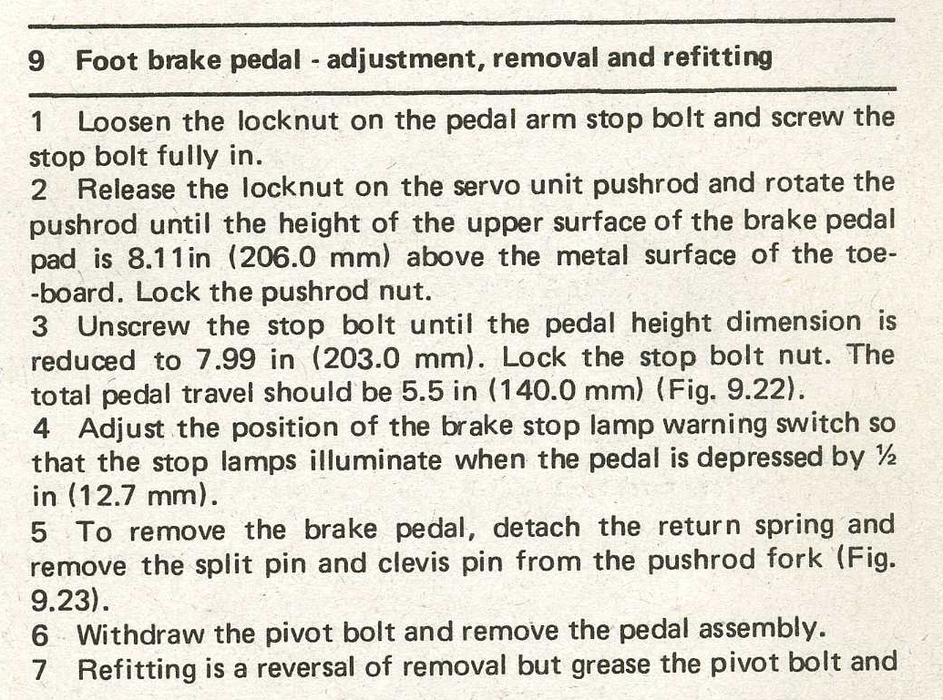
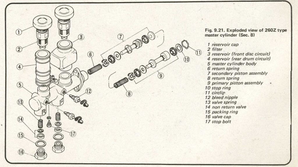
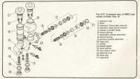
The flat head screw is, I think, P/N 17 in the diagram. NOT USER SERVICEABLE as they say:finger:
-
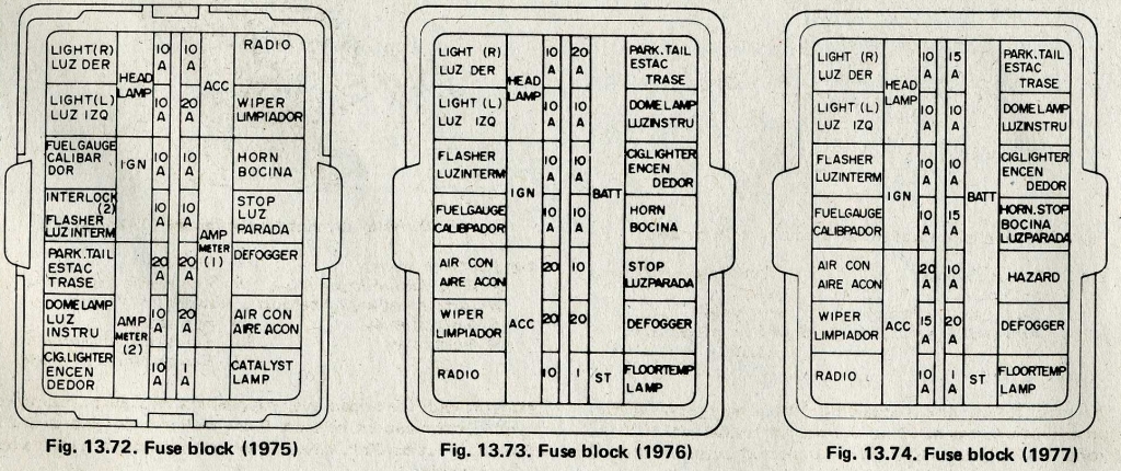
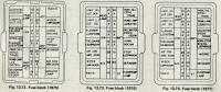
Fuse box covers. If this car has been "modified" for the track, I don't envy you restoring everything to street trim:nervous:

-
Here are the fuse blocks for the '75 - '77 Z's. I think there may be a fuseable link in the engine bay that feeds the headlamp fuses. I tried tracing the wiring on my Haynes diagram, went blind very quickly:disappoin
-
Like he said. We had the weird setup last week of all these systems simultaneously: - 1. extended heat wave across the southern 1/2 of Oz 2. storms on the Eastern seaboard closing beaches and causing coastal flooding, and 3. a tropical cyclone battering Darwin on the north coast. Forecast this week is for an extensive locust plague and herds of kangaroo wreaking havoc in Shopping Malls:nervous: Al Gore has a LOT to answer for :rolleyes:
-
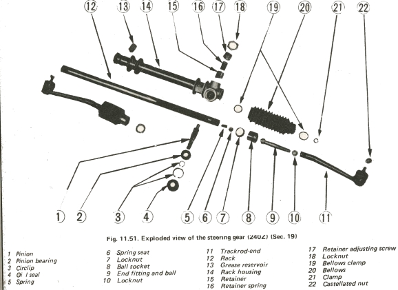
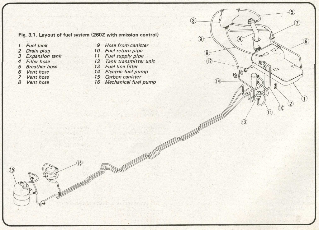
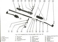
I'll make the assumption that you are talking about the ball joint locknut located at the steering knuckle at the front wheel. Castellated nut, P/N#22 in the diag. There is possibly a thread issue preventing the nut from turning further down the ball joint stud. Try a different nut, just to see if the stud is OK. If it screws on all the way then all you need to do is clean out the threads of the original nut or replace the nut. If it doesn't fix the problem then you will need to run a thread die over the stud to cleanup the threads. Thread size is 12mm x 1.25mm pitch. It is just possible to insert a scriber point through the stud shaft where the split pin goes to provide a locking method for the stud. Sometimes it can be just enough to get the nut to pass through the tough bit:classic: On my 1973 240Z, the fuel lines are all metal, with rubber only where the rigid lines mate up to the tank and fuel pump. Perhaps yours are missing?? Anyhoo, they are normally metal, bundy tube is fine:) Pic. 2 shows pipes for a 260Z.

-
Take TWO:nervous:
-
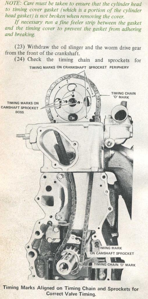
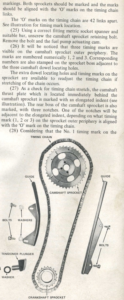
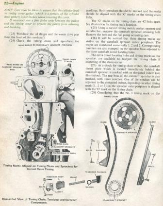
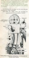
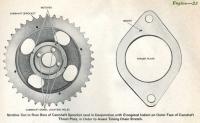
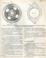
Here is a wee bit of info. I hope it helps. DON'T rotate the engine UNTIL you correct the cam timing:finger::finger:

-
.....or as my dear old Dad used to say..... "Work is the curse of the drinking man!" LOLLOLLOL
-
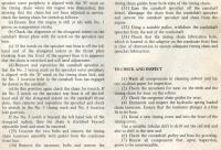
"For 6 cylinder engines, bore spacing is 3.799" [96.5mm] between cylinders 1-2, 2-3, 4-5 and 5-6, and 3.858" [98mm] between cylinders 3-4." From "How to Rebuild Your NISSAN/DATSUN OHC Engine" by Tom Monroe.
-
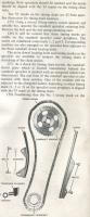
You can do a simple static test to determine if the points plate is generating spark. Make sure the points are closed, turn the ignition ON and open the points with your thumbnail or a small screwdriver. The points should arc slightly and pulse the ignition coil. If you connect an earthed sparkplug to the coil to cap High Tension connection, the plug should spark with a nice big fat BLUE spark. If that doesn't happen then there is no point, pun intended, in cranking the engine:( If that does happen then re-fit the cap and take it from there.
-
I personally feel that Automotive Paint Stripper is the safest and most effective. Sure, it is messy, but if you use a lot of newspaper or a painters disposable dropsheet to catch any fallout and leave the scrapings in a cardboard box or similar, it is reasonably easy to do. Make sure you wash the panel down well with water to neutralise the remaining stripper. I use a variety of scrubbing brushes and a bucket of warm water with a dose of de-greaser after neutralising to remove any stripper trapped in cracks and crevices. Any form of abrading will create dust, heat and such, which I feel is undesirable. There is no way that abrading will get into those areas that the stripper can.
-
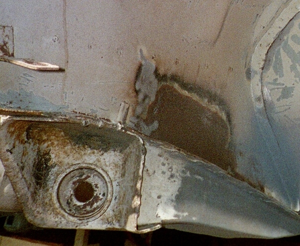
Methinks it is a panel to prevent the gas/petrol tank from getting pierced by the rearward facing fasteners, in the event of a rear end shunt:ermm:
-
12mm x 1.25P is the standard wheel stud dimension for a Z. Unless they have been changed sometime that is the specs. of the nut you need. The difficult part most likely is to get the flat shoulder with washer setup that the wheels require:(
-
Only guessing but pehaps the locking mechanism for the recliner cogs are out of synch. Look for a wire tie or bar connecting the sides of the seat. You may have to jiggle the locks independantly to straighten the squab up in relation to the back rest:ermm:
-
Welcome, I see you are from the East Island:nervous: I'm from the West IslandROFL S30s' would be a little hard to come by in your area wouldn't they?
-
I'm guessing you are referring to the radius rod mount. You will either have to have a new one folded up and welded in or hack one off a wreck. If you can post a pic. of the damaged one, perhaps we can advise the best course of action, repair or replace:ermm: Is this the bit causing you grief? [This is actually the passanger side of a RHD '73 240Z]