inline6
 Subscriber
-
Joined
-
Last visited
Everything posted by inline6
-
 Yes, please let me know how thick yours is. Uncharacteristic of me, I threw mine away before measuring and the trash got taken away today!
 -
Just looking in the manual that came with my compressor and the oil specified is: API SG/CD Heavy Duty* with * = (DeVilbiss Brand DV1721-040 can also be used in this compressor) Grade info: SAE 20 Below 20 degrees F SAE 40 Above 32 degrees F Don't know what you do if between 20 and 32... hahaha I also don't see ISO 100 anywhere on the bottle I bought. No idea at the moment what to do with the info "API SG/CD" and the bottle of stuff I bought.
-
Oh. That is interesting. Thanks Steve. Looks like I should investigate API CC SAE and ISO 100 - consult my compressor manual and may need to remove and replace the $44 dollars worth of oil I just put in recently. I'll investigate.
-
I am not good at draining from the tank. It's more of a pain to do than it should be, so I tend to ignore it. I probably drain it about twice a year on average. I need to do something to make it less of pain, maybe put a shallow pan underneath with an outlet in a good location. Right now, where the compressor is located, when I open the drain valve, the water runs toward a wall in my shop and gets the base of the wall wet. The lines are easy to drain. I drain them frequently.
-
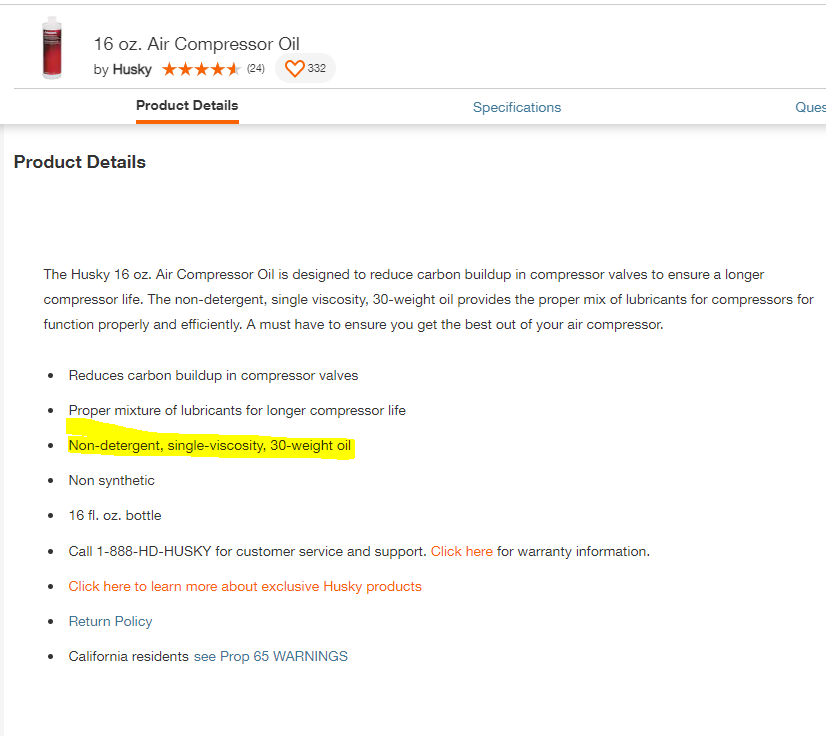
From the product details of what I bought:
-
Yes. For many of those years, it got little use. I am unsure of how many times, but probably about 6. I just changed it about a month ago before I started on a rather lengthy round of blasting all of the black parts for the car I am restoring. I was shocked at the price of the compressor oil - nearly $12 for each 16 ounce bottle. And it took 3 and half of these. https://www.homedepot.com/p/Husky-16-oz-Air-Compressor-Oil-HDA10700AV/100096995
-
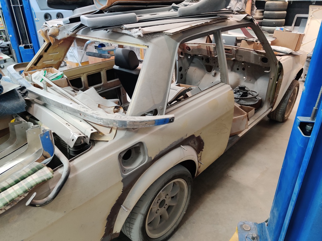
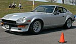
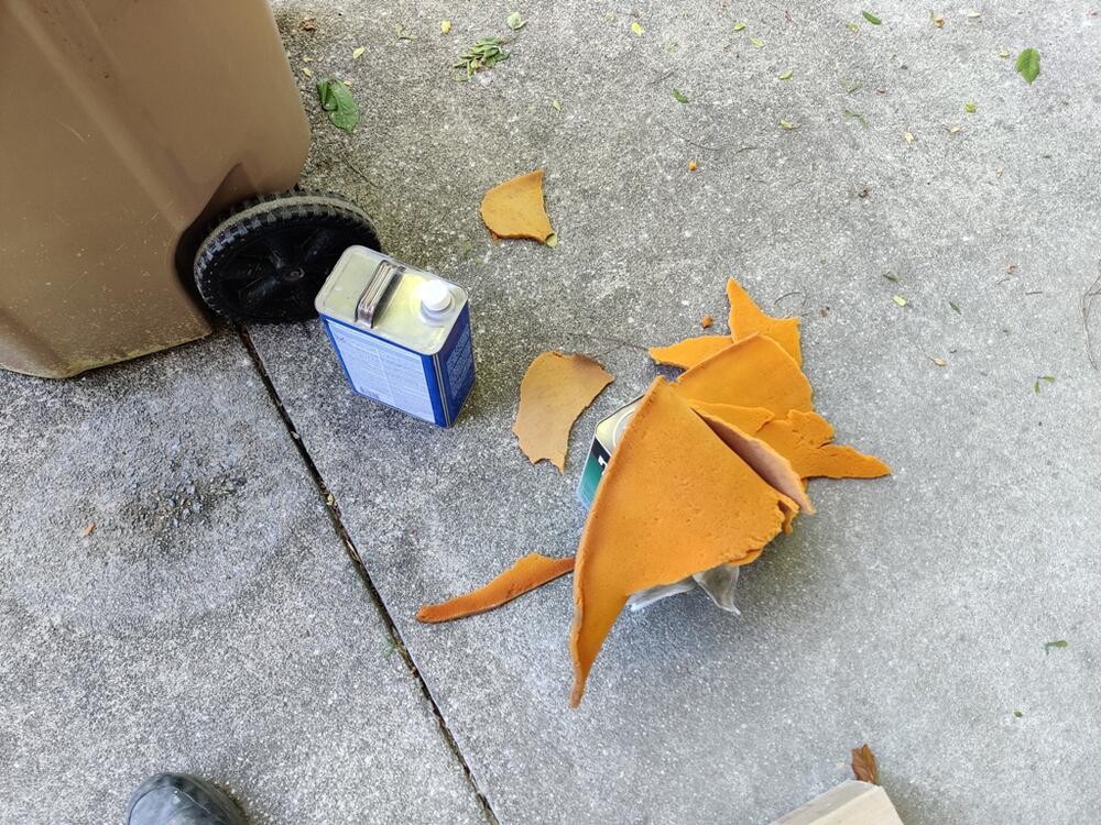
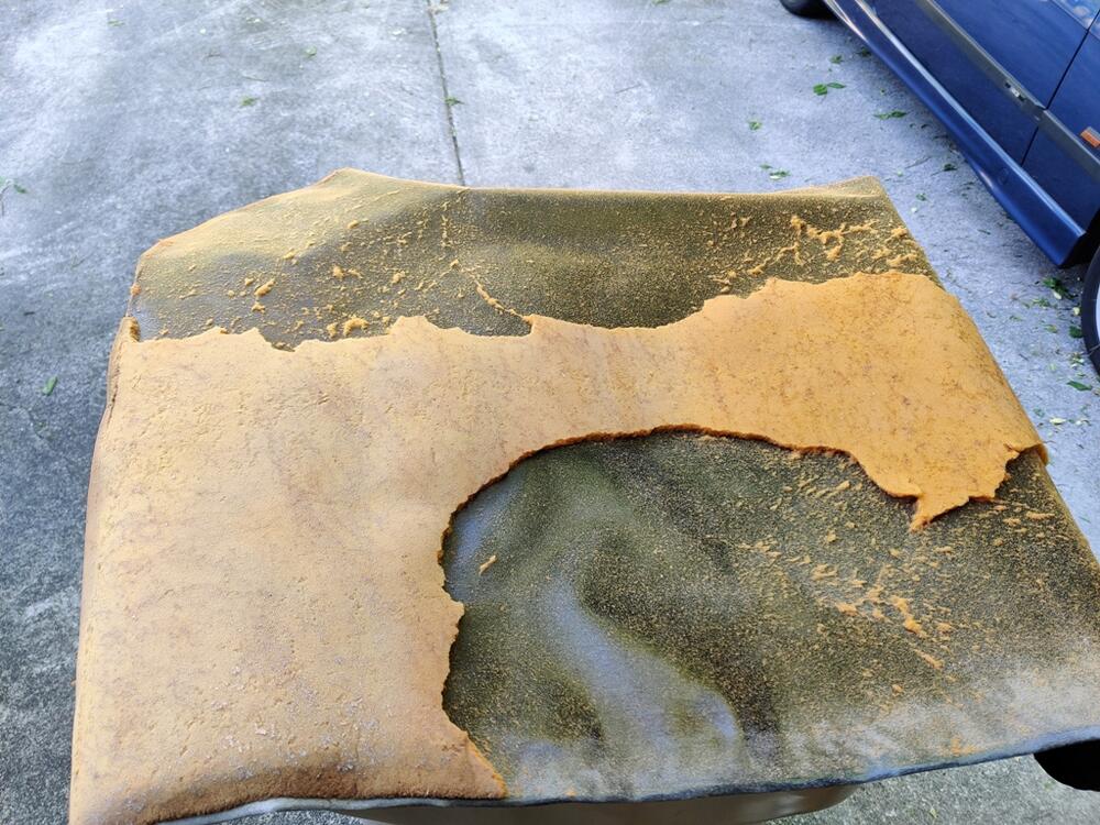
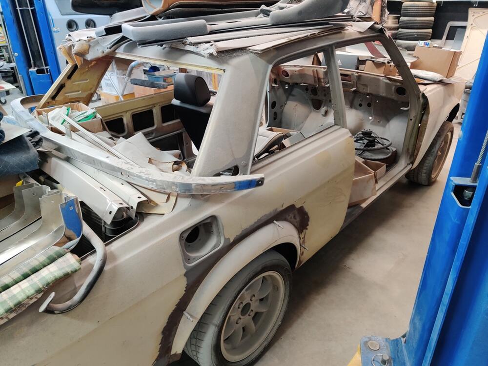
I took a break from working on parts restoration, and cleaned up one of the neglected corners of my garage on Sunday. About two and half years of bodywork on the Z had coated everything in the corner including the 510 pictured above with a layer of primer dust - and a ridiculously expensive layer at that! The 240z headliner was one of the parts I was storing on the 510 and as I was blowing dust off of various things, I got distracted by the headliner. I destroyed one of these years ago when I tried to remove the dead foam. I think I was using a razor blade to carefully remove the foam and I cut through the vinyl. That method was not a good one. This time, I decided to carefully peel it off by hand. It wasn't too bad a job, taking somewhat less than one hour. My plan is to purchase new foam and glue it to the old vinyl. I will probably use a roller to apply it. Because I have seen vinyl come loose after a short period of time on too many Z restorations, I bought this adhesive for all the vinyl for my car: https://www.yourautotrim.com/2gacadapwehh.html I have some experience with using contact adhesive and have found it to be critical to wait a sufficient period of time. Anyway, installing interior vinyl is a project for another day - the painter still hasn't started his part on my project yet to my knowledge.
-
I think the fees eBay charges to sell auto parts are too high. Will be interesting if these first items sell and if Jim likes the results.
-
Yep - it sounds like you and I are both of the opinion that using snap ring thickness to adjust center line of the shaft with the axle outputs is not likely. Picking the right snap ring was probably done like you said. I was just pointing out that trunnions probably vary a bit as well.
-
I don't think they would have been able to keep the tolerances of the u-joint trunnions to the exact same distance in width. Same for the width between the yoke ears. I could see the total differences in both varying enough to total a couple of thousandths one way or the other, necessitating the use of different thickness snap rings. Either way, I have a hard time believing the snap ring thicknesses were used to correct machining "off center" of the center line of the axles or output shafts. But I don't know that wasn't done also. Additionally, maybe a axle that is a thousandth or so "out of round" isn't a big deal?
-
After my additional experience with "sizing" the snap rings on these axles, I will be revisiting the work I did previously to replace the u-joints on the driveshaft. I did not check free play. One of the joints, if not both, was a GMB (brand). I don't recall ever seeing anything but a single size thickness snap ring supplied with aftermarket u-joints, so it should be interesting to see the free play I currently have on the each u-joint in the driveshaft. I am guessing they are a bit loose.
-
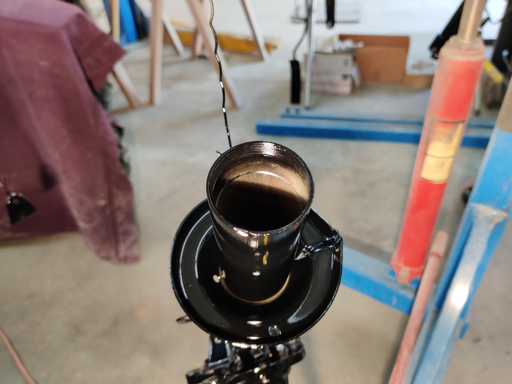
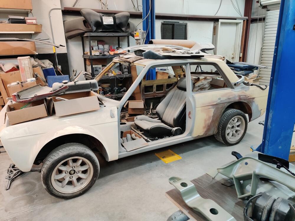
I have finished installing the new OEM U-joints in my axles. Here is a separate thread about it if you want to check that out. It took roughly 12 hours to do what I thought might take 2. The snap rings are a pain in the butt, and the odd angle on the axle output flanges make u-joint removal and installation in a press way more difficult than it should be. Plus, getting the tolerances right, and measuring to confirm they are, takes a lot of time. Definitely best to get all that done before priming and painting them. I am actually thinking of sending them off to have them balanced, so I will likely hold off on priming or painting them until they come back. After he better part of a day and half of working on them, I decided to clean up the shop a bit. This "shelf" for some of my 240Z parts is incredibly dusty after years of doing body work on the 240Z in my garage: Someday, not too far off in the distance, this will become my primary project!

-
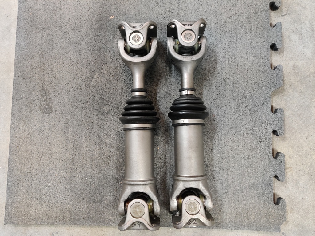
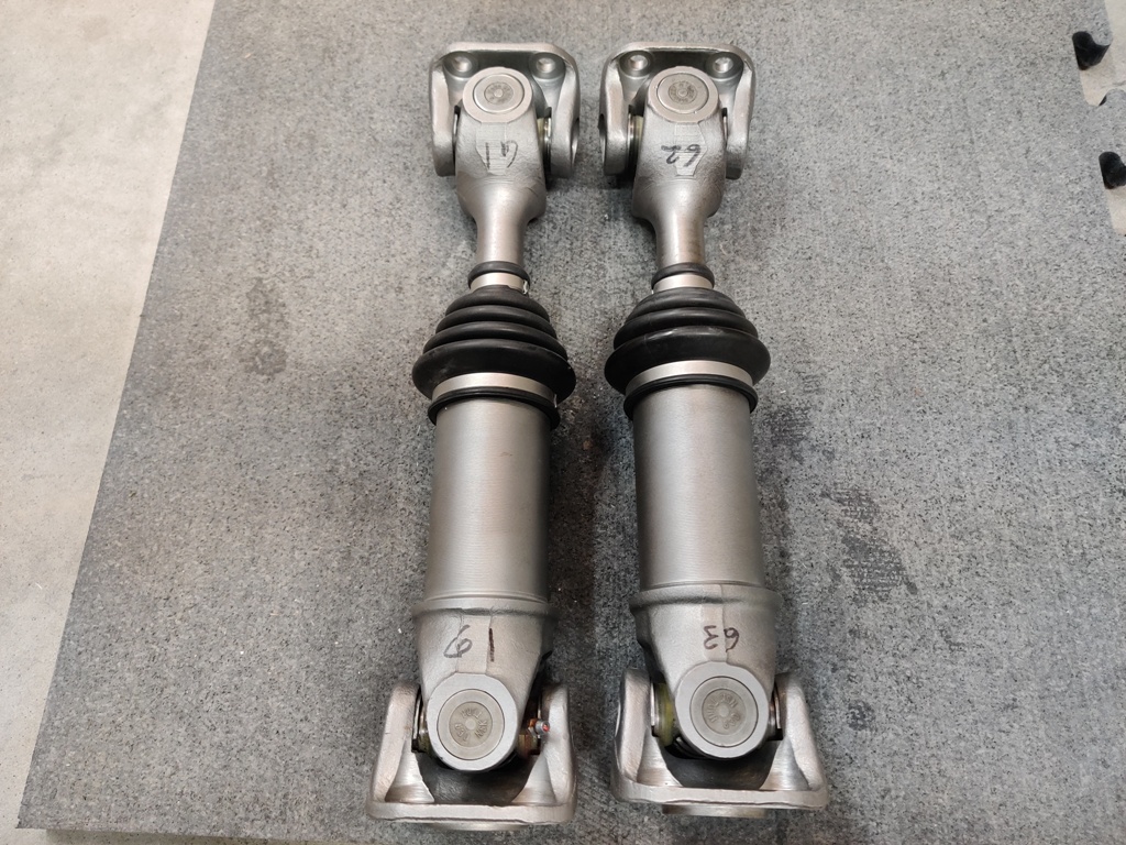
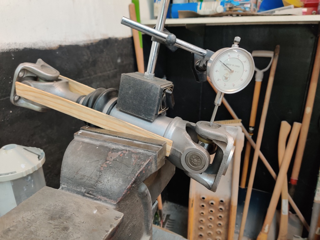
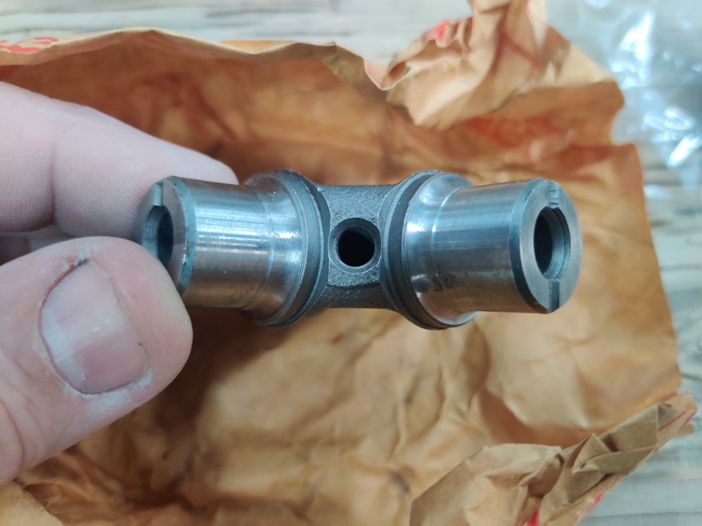
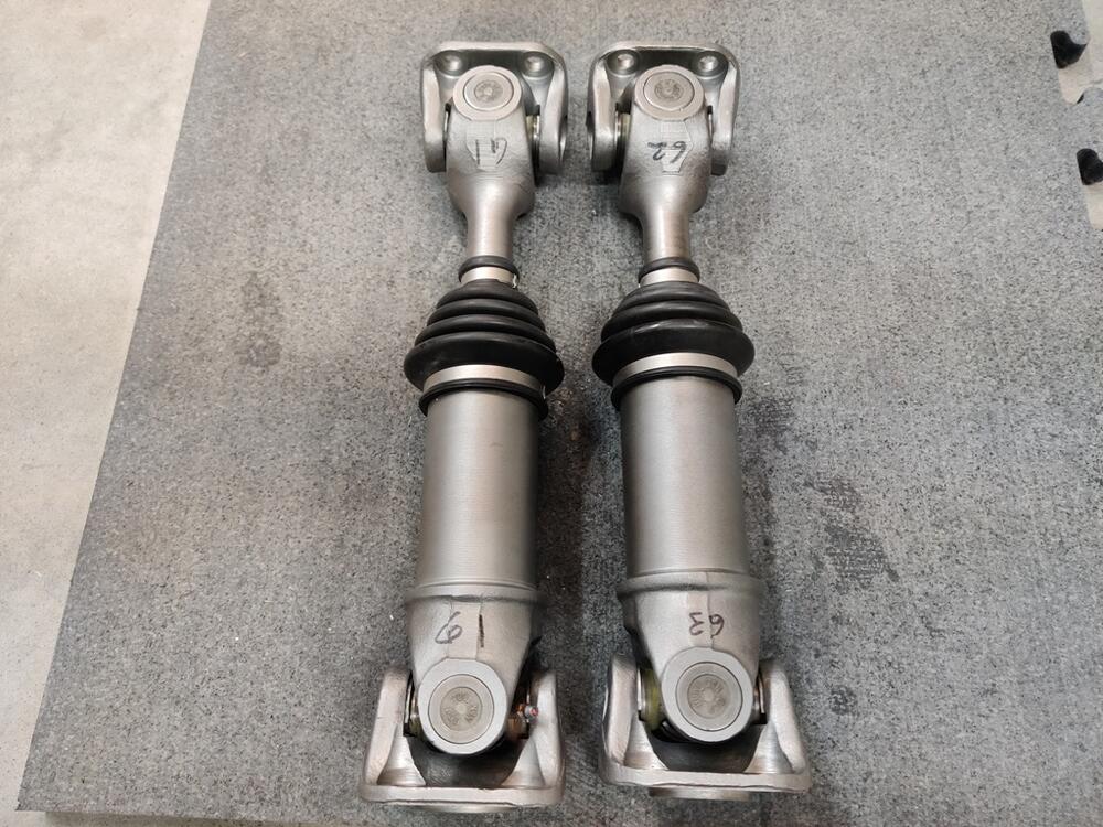
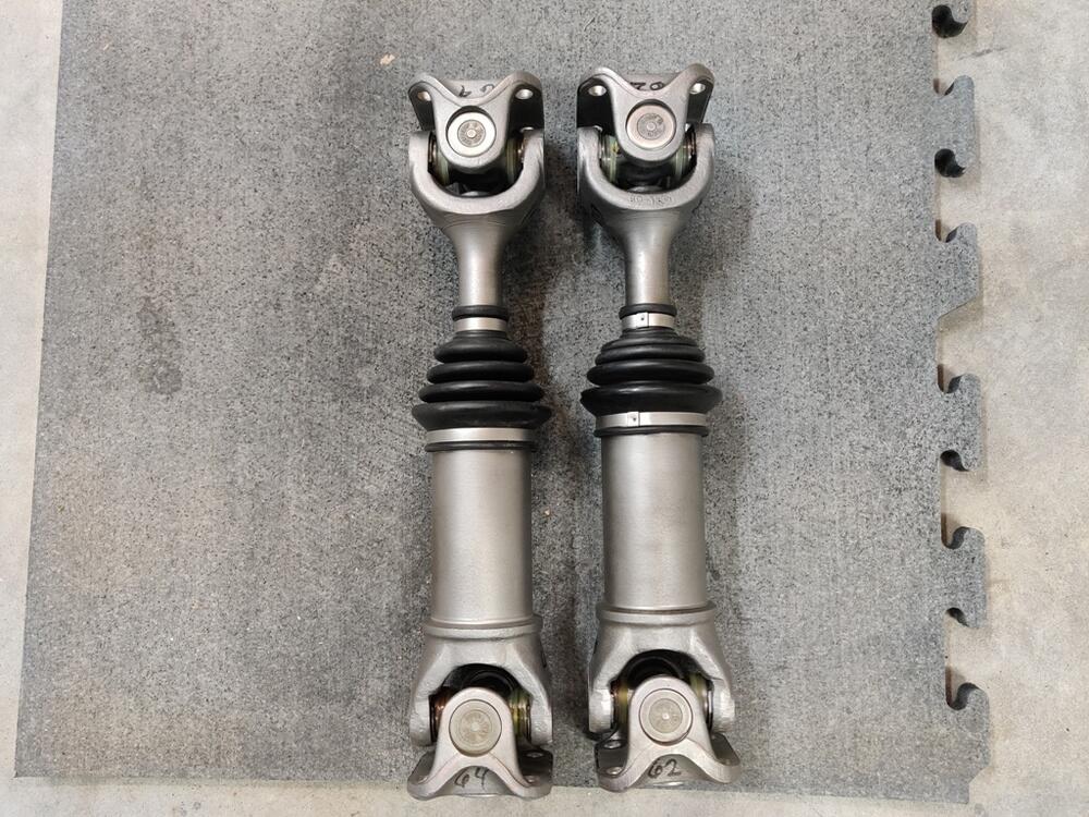
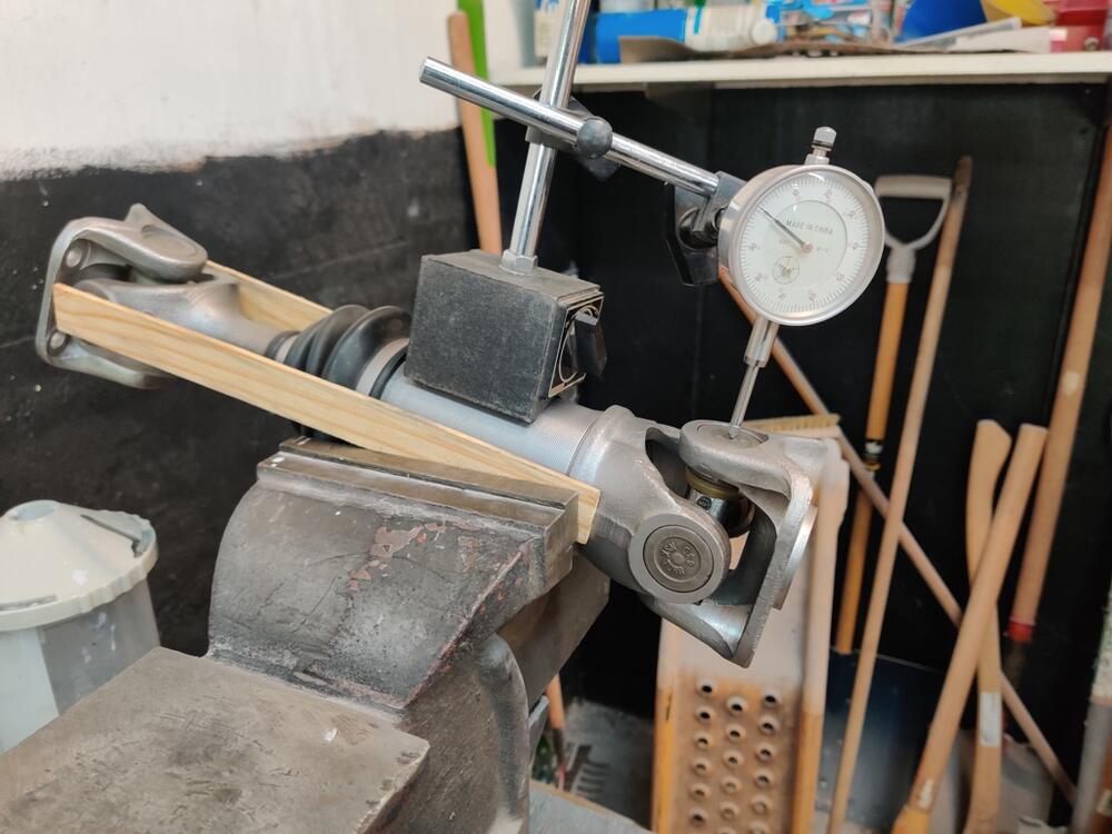
I think someone was here before me, so too late not to change anything. I examined only one of the axles with regard to the arrows I mentioned at the beginning of this thread. The arrows pointed to a "flatter" of the four corners of the trunnion, but they were not drilled and tapped for grease fittings. The relationship was 90 degrees one to the other, not 180, or in alignment. Thanks for the tip about brass jaws. I was able to get the snap rings matched up for each opposing journal pair. .062" was the most common size snap ring I needed to use. If I recall correctly, the new snap rings which came in the package with each of the new u-joints were of the following sizes: .060", .061", .062" and .064", .065", .066" There were 12 supplied with each u-joint - two each of those sizes. Oddly, .063" seemed not to be present. I carefully lapped two .064" snap rings to get the .063" I needed. With the axle in the vise and using the dial gauge, I was able to confirm about .001" of free play axially for each direction on the trunnion. The u-joints feel a bit "heavy" in their movement. However, I am certain after very careful checking that the free play is what it should be. I could see the needle on the dial gauge move easily and then stop, as I applied pressure to move the u-joints up and down in their installed state. I may very well send the axles off for balancing. Since I am installing a 240SX transmission, I may need to get a driveshaft made also. If I can use my driveshaft as is, which may be possible, I will likely send it off for balancing with the axles. Numbers indicate the snap ring used in thousandths at each location with opposite journals using same sizes, of course.

-
That thought occurred to me, but it seems too cumbersome from a production efficiency standpoint to me. I could go through and swap out rings to get them as close to the same size as possible, and then send the axles (and driveshaft) to a driveshaft balancing place like you mention to check balance / re-balance. I believe I worked with The Driveshaft Shop on a group buy of short axles for a Z31 CV conversion on my highly modified 240Z many years ago. They are in NC. Who are you referring to in SC?
-
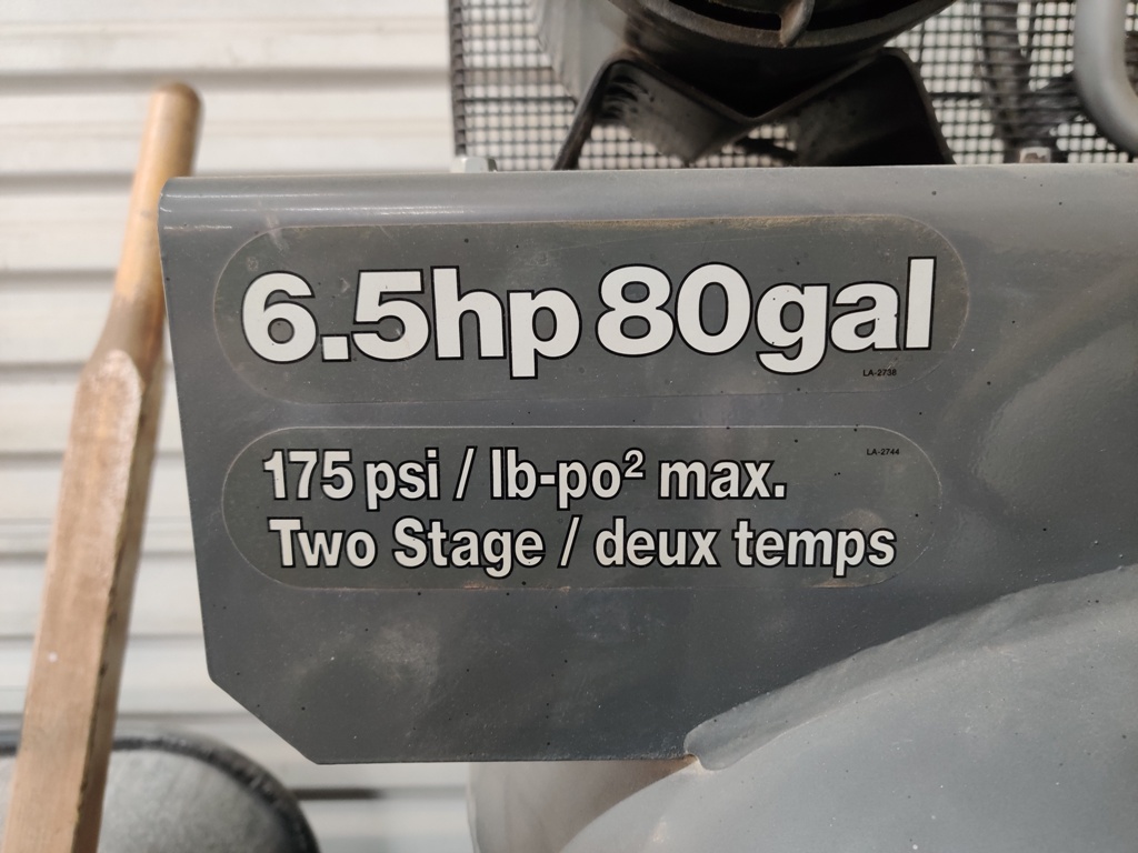
Good questions. I see the label has "deux temps". I think that is French. A Google search seems to indicate the french use lb-po^2. It is equivalent to psi. My compressor pump is an "inline 2", with the cylinders side by side. One is smaller than the other. The larger one is the low pressure part of the pump, and the smaller one is the high pressure part. Looking at the paperwork I have for it, I see I bought it on 11/01/1997 for $709.77. 🙂 I bought my glass bead cabinet at the same time - just after I bought my first garage (with a house attached hahaha). It was my first expensive tool purchase. I was 28... It will be a sad day when/if this compressor wears out. But we are both getting old!
-
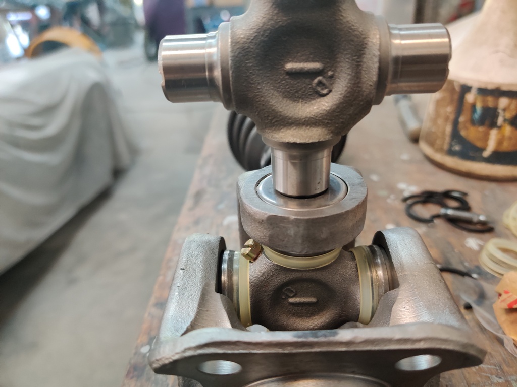
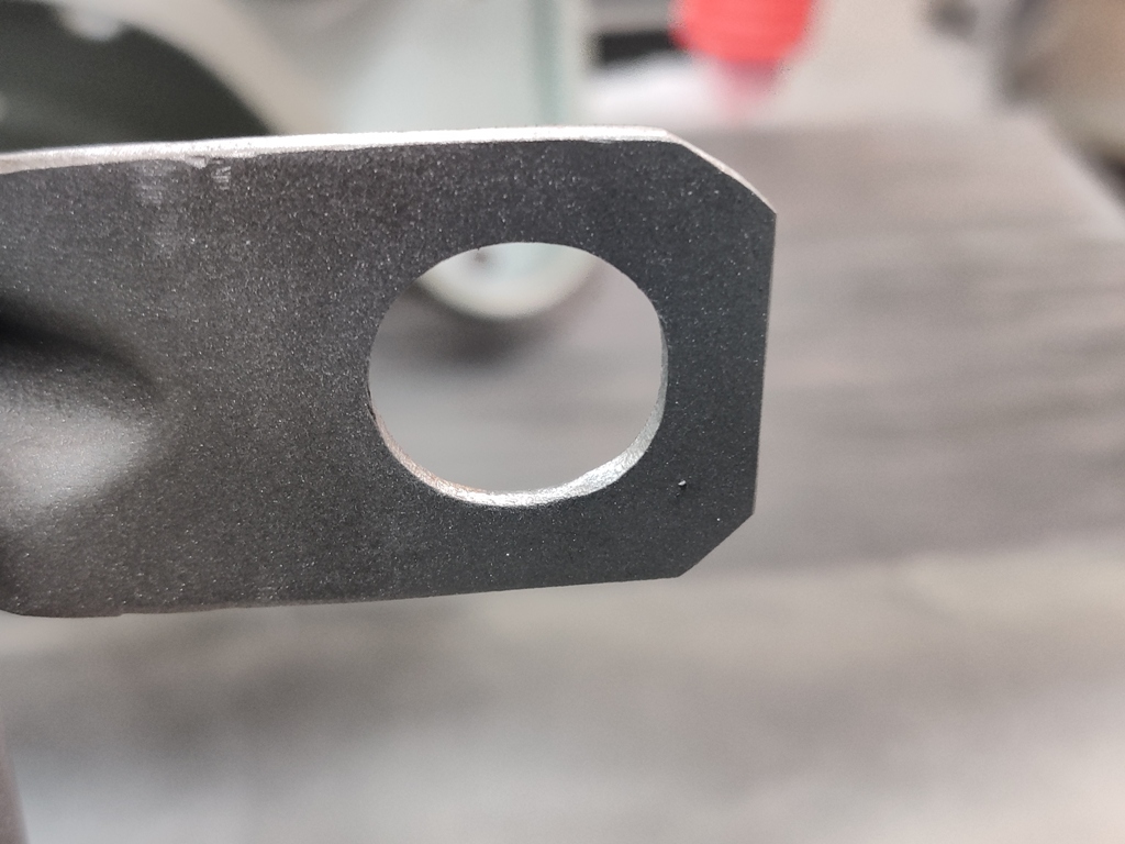
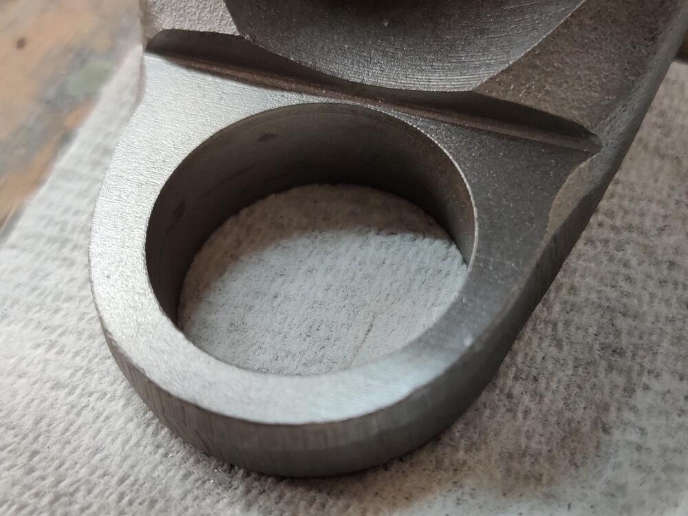
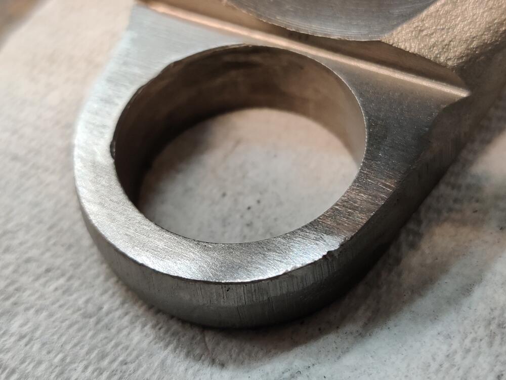
I am surprised at how many hours it took to replace the u-joints. What took the most time was measuring everything and trying different snap rings until I got the right factory free play of about one thousandth (factory spec = .0008"). However... I realized something much later in the day, and I'm going to have to go through snap ring sizing part again. Let me explain why: Generally speaking, the distance between the yoke ears on both the center axle assemblies and between the yoke ears on the outer axle flanges measures around 2.200 to 2.205 from inside surface to inside surface. To measure the u-joints where it matters, I installed opposing needle bearing caps, and put the u-joint in a vise, squeezing it lightly until the caps bottomed out on the u-joint spider. I used paint sticks to protect the caps from the vise jaws. While in the vise, I took vernier calipers and measured from innermost edge of snap ring groove to the same innermost edge of the opposing cap. That measurement was about 2.080. The difference, divided by two, is theoretically the snap ring size you need on each snap ring groove - or close, anyway. So, by the measurements I was seeing, (2.205 minus 2.080) divided by 2 equals .0625. I didn't realize the info in the paragraph above until I was working on the second axle. Additionally, while working on the second axle, I began to suspect that the u-joints may have been replaced before. The first thing that tipped me off to this was that on the second axle, I was more diligent with measuring each of the snap rings as I removed them. And I kept track of their respective locations. For the second axle, here is what I found when I took them out: Inboard u-joint: "Top of axle (arbitrary, but I marked it as such)": snap ring - .060" --- opposite journal - "bottom of axle": .062", and "left" journal: .062" and opposite "right" journal: .065" Outboard u-joint: "Top of axle": snap ring - .060" --- opposite journal - "bottom of axle": .062", and "left" journal: .065" and opposite "right" journal: .062" Thinking about the snap rings... I just don't see how it could be right to use different thicknesses on paired journals. Maybe I am wrong, but certainly from an ideal standpoint, the outer flanges should be machined such that the 4 bolt holes which secure the axle to either the differential or axle - these would be oriented such that the center of the flange would align with the center of the u-joint. If the machining process on the outer flanges achieves this, when you install the u-joint and you use a snap ring of a thickness of .065" on one journal, and .062" on opposing side, then that u-joint is going to be .003" off center. And for every revolution of the axle, it is going to be .006" out-of-round. Seems bad... like it shouldn't be like that. Wouldn't that cause vibration? The second thing that indicated the u-joints had been replaced was some dings on the inside surfaces of the yoke ears. I am pretty certain I did not cause those. I lightly dressed them with a file so the snap rings were sure to fit properly. First pic: dressed some marks on the inside surface with a file. Second pic, no dressing was needed: Third pic: measuring u-joint free play: So, tomorrow, I'll be going over the axles one more time, looking for the right snap rings. The good news is that the total thickness of each pair of snap rings should be right, as I measured everything and got the free play right. However, for each opposing pair, I'll need to measure the thickness of each snap ring, and "split the difference". So, for example, the .062" and .065" combo will need to be swapped out for two .063" or two .064" snap rings - whichever gets me closest to the .0008" free play.
-
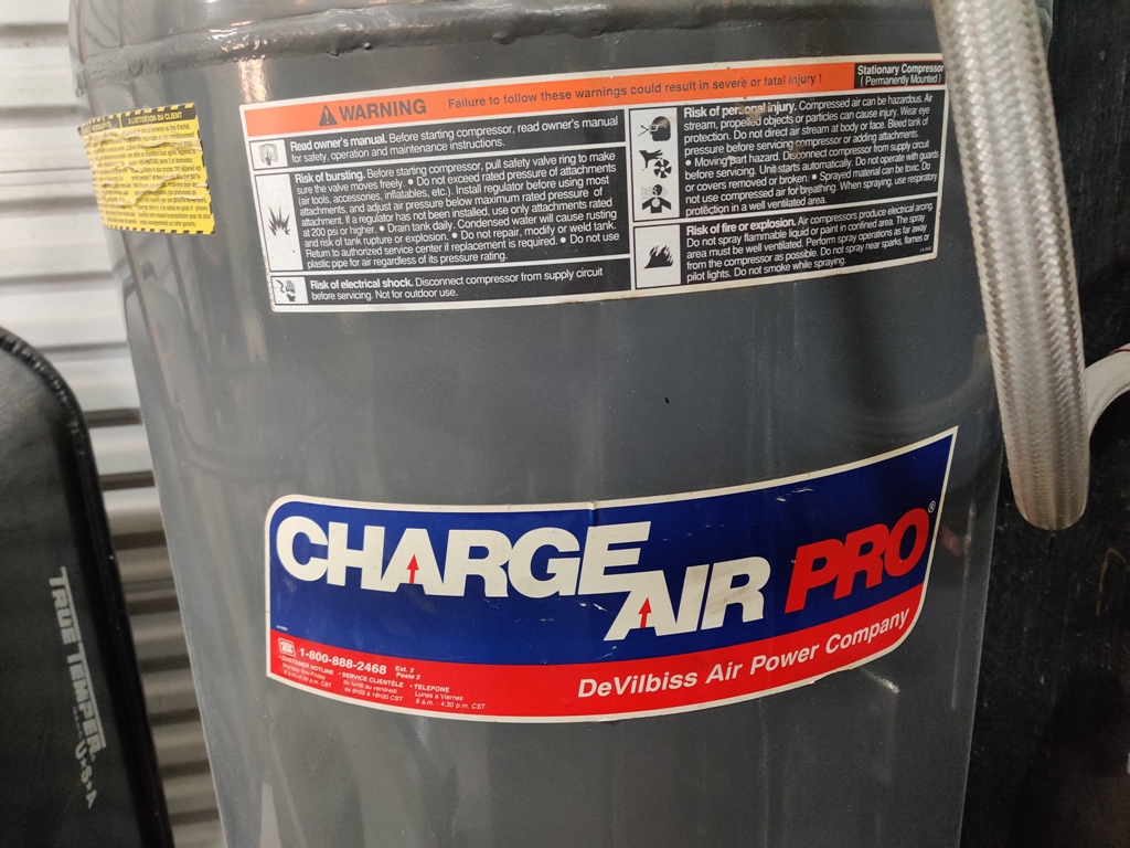
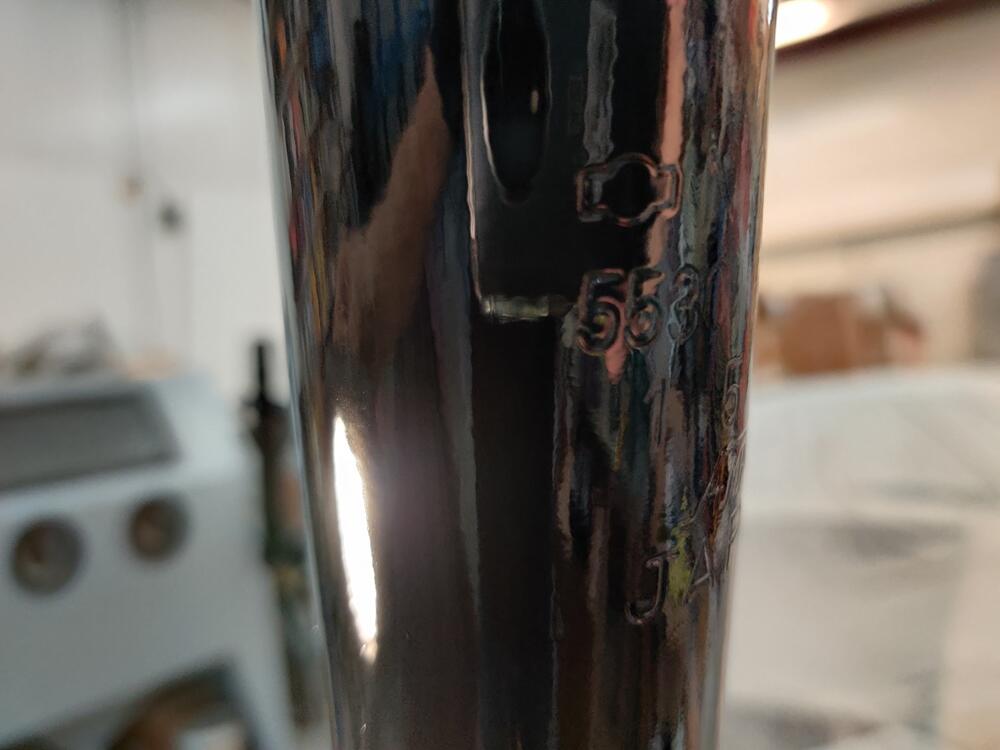
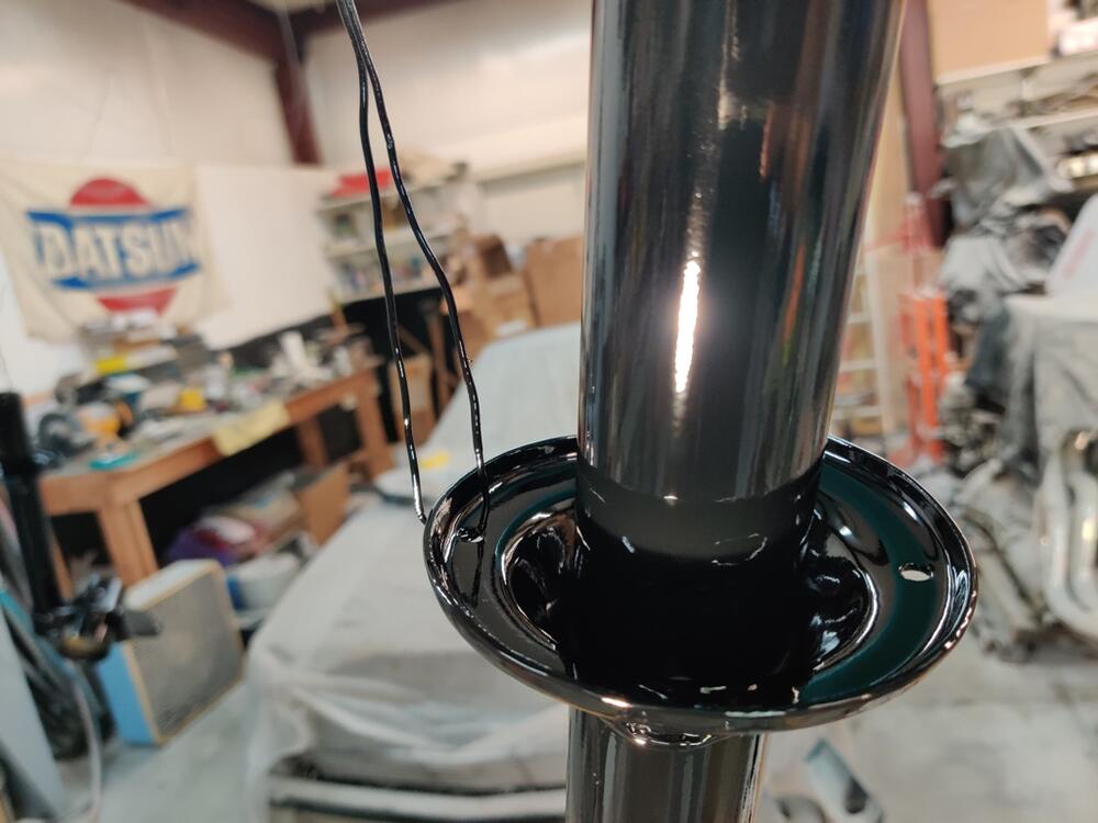
Pictures of my compressor: 55 I was able to adjust the new switch to kick in around 120 and turn of at about 155, just as before.


-
Thanks for the info guys. I will take a picture of my compressor today and put it here - that pic above was the same model, but a picture I found online. It/mine is a two cylinder compressor. I bought the compressor when it was new. The switch I replaced was the original one. I don't think it was adjustable, so I found it odd that both had 140/175 specs, but that the original worked at 120/155. Good point about adding more heat. Yeah, agree, it doesn't look like any benefit to keeping the higher points. I will adjust them both down today.
-
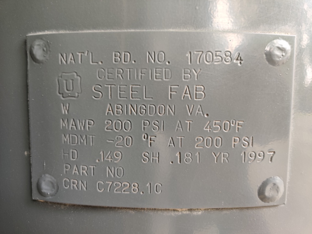
My trusty compressor developed a problem with its pressure switch. The contact started sticking and the compressor kept running even when the tank pressure exceeded the cut off pressure. I've had it for about 27 years, and used it a fair amount given I am just a hobbyist. I am too lazy to get a picture of it, but it is this same model - though I think it was branded under Campbell Hausfeld: So the switch - I went online looking for replacements. The original switch had the model "DAC-278-1" with number 140 and 175 which apparently indicate the turn off psi and turn off psi. Since I bought it new... for 27 years, it turned on around 120 psi and turned off at 155 psi. Tonight, the $18.95 replacement arrived and I installed it. Here is the one I bought: https://www.amazon.com/dp/B00273R6KU?psc=1&ref=ppx_pop_dt_b_product_details Interestingly, this switch kicks the compressor motor on at about 145 psi and turns it off at about 175 psi. And this one, has screws to allow adjustment to the turn on and turn off points. My question is this, is it harder on the compressor to utilize 145/175 instead of 120/155? It seems logical that to get to 175, it has to run longer than to get to 155. But, if it kicks in at a higher pressure also, maybe it ends up running the same amount of time when air is not being used? And then, there is reality - I consume air while it is running quite often, like for sand blasting or glass bead blasting. And pretty much all of my tools are limited to 90 psi... So, is it wasteful or unnecessary to run 145/175? For what its worth, my lines are cast iron pipe and the water separator and regulator are rated for 200 psi max, the hose is rated sufficiently high enough, etc.
-
I find it curious that the snap rings supplied with the new u-joint are in thicknesses which are paired in twos and thicker and thinner than what I took out. Possibly they were trying to supply a broader range on purpose. Consider, why not provide 3 groups of 4 of the same size, for example? I am going to take some measurements of the distance between the yoke ears or whatever you call them. Perhaps the distances vary a bit and will give me guidance on what thickness snap rings need to be used. It will be interesting to see variances.
-
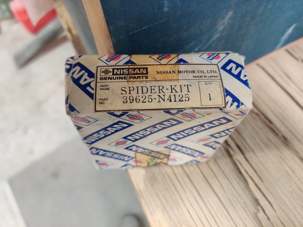
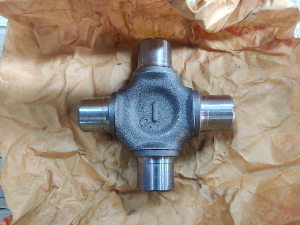
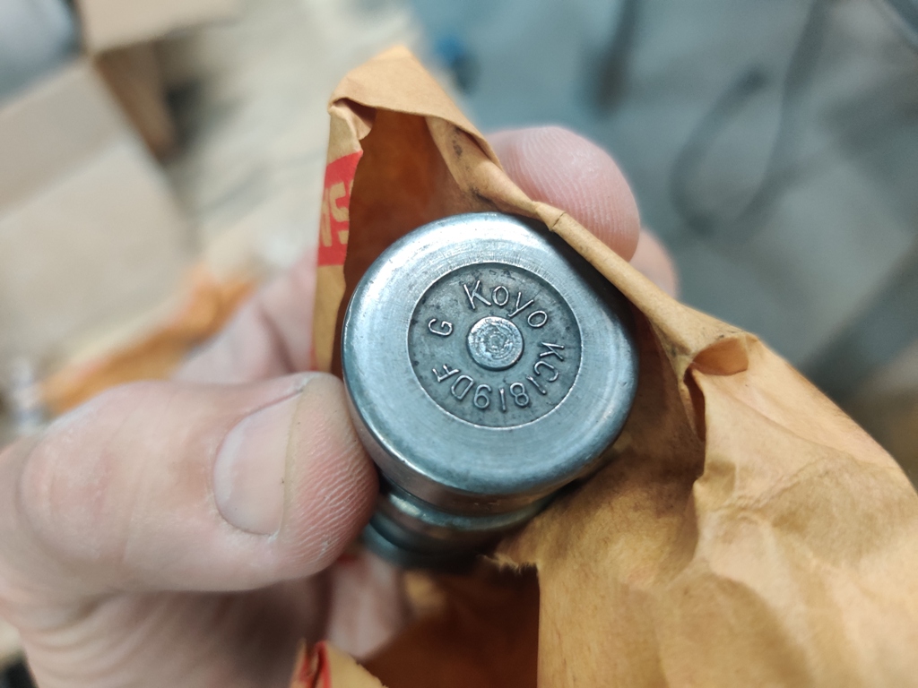
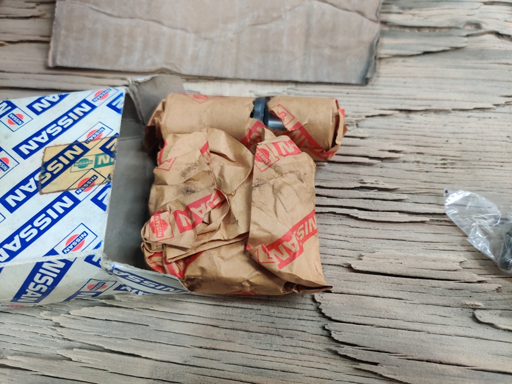
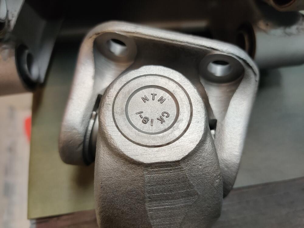
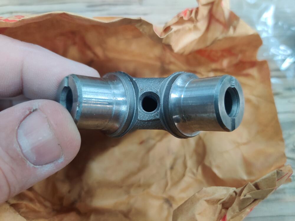
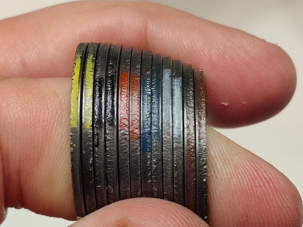
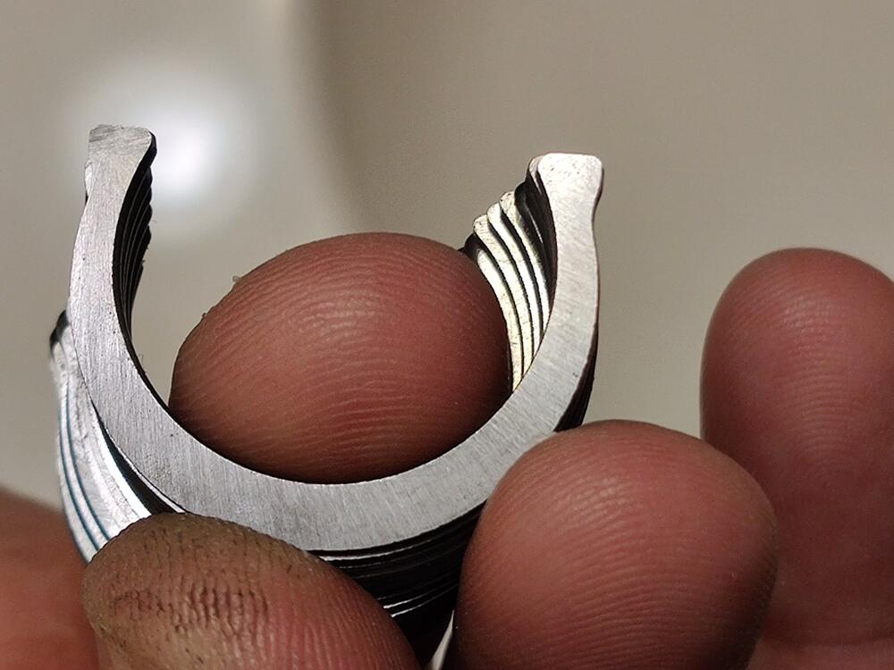
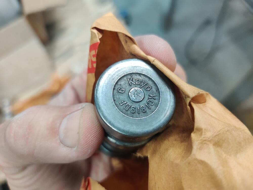
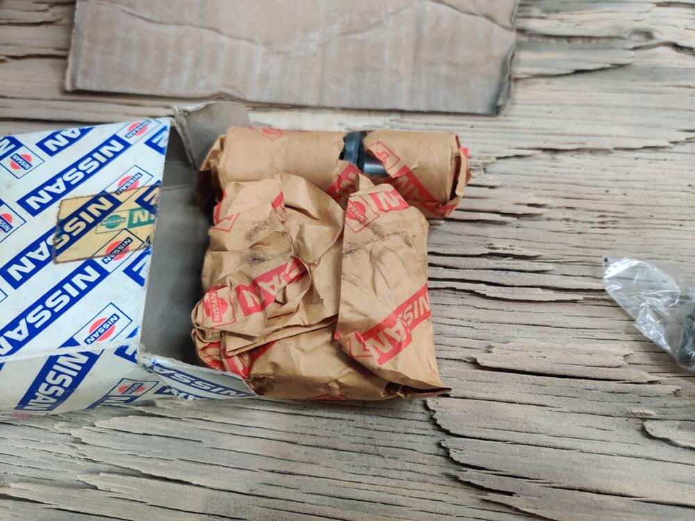
I have started replacing the u-joints the 240Z I am restoring. I think the u-joints I removed are original to car. Can anyone confirm? What tells me they are factory? Well, there is a fair amount of evidence from looking at the history of the car, the receipts, and the amount of crusted dirt that was on the u-joints. Basically, the car appears to have about 120k miles on it - a notable amount of crust that I had to remove from the u-joint spider, and the snap rings I removed look just like the ones that came with the NOS u-joints (different from all the aftermarket u-joint snap rings I have ever seen). Anyway, on to some selected text from the factory shop manual and some questions. When looking at the RA chapter from the workshop manual (Rear Axle & Rear Suspension)... First, a little bit of levity - per the manual, did you know that "The drive shaft should be disassembled only when lubricating the ball spline" and further "The lubrication is required every 50,0000 km (30,000 miles)"? Bet you didn't, and you'd better get on that. 😛 Setting that aside, oddly, when addressing replacing the universal joints from the axles, the factory workshop manual refers the reader to the "instructions described in the paragraph covering the propeller shaft if faulty condition is detected". So, I turned to that section of the manual. Unfortunately, the propeller shaft (drive shaft) is a bit different than the axles. So, I am left with some ambiguity and therefore, some questions. Let's start with "Before disassembling the journal, verify the component alignment and relationship so that the yoke direction and snap ring thickness are not changed (when the yoke direction and/or snap ring thickness is changed, the tube and journal center alignment is deviated and the propeller shaft is unbalanced) because the journal is balanced as an assembly. It is desired not to disassemble the propeller shaft so that the alignment is not unbalanced." So, translation? Don't take it apart if it can be avoided. Of course, I have already taken the u joints out and found them to be in need of replacement. I have only disassembled one axle - just the u-joints removed so far. And before I did so, I marked everything so as to keep all parts in their factory assembled orientation. Axle yokes, axle, u joints, u joint snap rings... all laid out per their assembled orientation. Now, a few words about the new oem u-joints. These are new old stock. Note that the D and "dot" seem to be indicating where the u-joint is drilled and tapped for a grease fitting (the package includes a screw plug): These original equipment u-joints come with an assortment of snap rings: Note the colors painted on the edges. There appear to be 6 sets of two. The factory workshop manual only provides info for 4 colors, and those are for the driveshaft u-joints, which are different than the axle u-joint snap rings. Those for the driveshaft are measurably thicker, varying from 2.00 to 2.06 mm (.0787 to .0811 inches). I measured the snap rings that came with the axle u-joints. Generally speaking, they range from .059" to .066". So.... One of my more important questions is, what snap rings should I use? Turning again to what is written in the workshop manual: "Reassembly" "The component parts are reassembled in reverse sequence of disassembly. When reassembling, select and use a proper snap ring out of the following types (four types) so that the journal moves under the following conditions: 1. Bending resistance of the journal unit is less than 1- kg-cm (9 in-lb). 2. When a yoke in one side is set stationary and a load of 10 kg (22 lbs) is applied to the other yoke alternately, the relative displacement of the yoke toward the axial direction is less than 0.02 mm (0.0008 in)." The four types, by the way, appear to be the four colors for the driveshaft u-joint. For the axle u-joint, it looks like we have 6 types (colors). My measurements of the supplied 6, again ranging from .059" to .066" roughly corresponded to two of each of the following: .059", .060", .061", .063", .065", and .066". Separately, the snap rings I removed from the old u-joint are mostly, to my measurement, .062". Interesting. Looking again at number 2 above, I think what I am supposed to do is use two snap rings of the same size at opposing journal locations. For example, I could install the old ones - .062" at each of the four journal locations, or perhaps two .062" opposite each other, along with two .061" opposite each other. Next, I should attempt to use a pressure of 22 lbs against the "other yoke" and check for axial movement (which would occur if the spider of the u-joint were to sink further into the u-joint cap. Success in determining the correct snap ring is achieved when "the relative displacement of the yoke toward the axial direction is less than 0.02 mm (0.0008 in). Right? Thoughts? I've been looking through all of this this evening trying to figure it out. I wonder... how many people install new u-joints and don't get the movement in the axial direction sufficiently tight? If axial movement is "too much", it could cause wild vibration. Lastly, I wonder if the grease fitting location on the u-joint matters in any way? So far, I have one new u-joint installed. Should I install the second one on the axle as pictured - with its grease fitting location 180 degrees opposite, in this orientation?


-
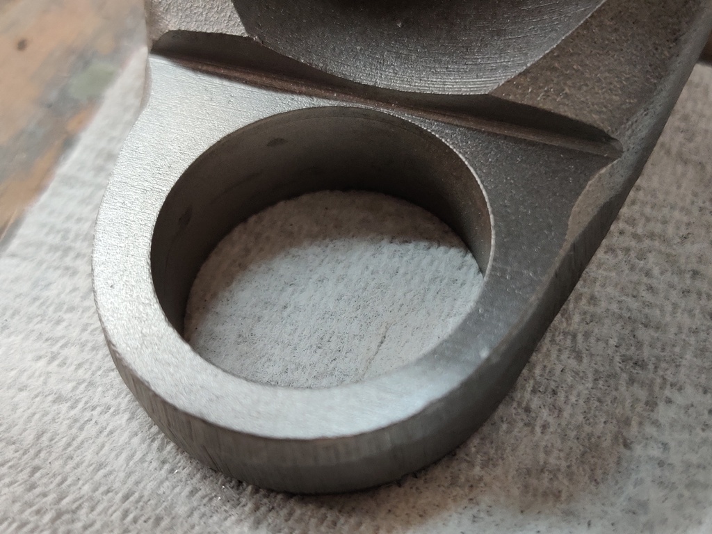
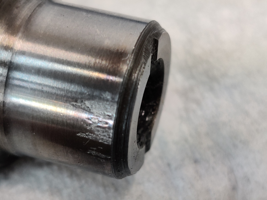
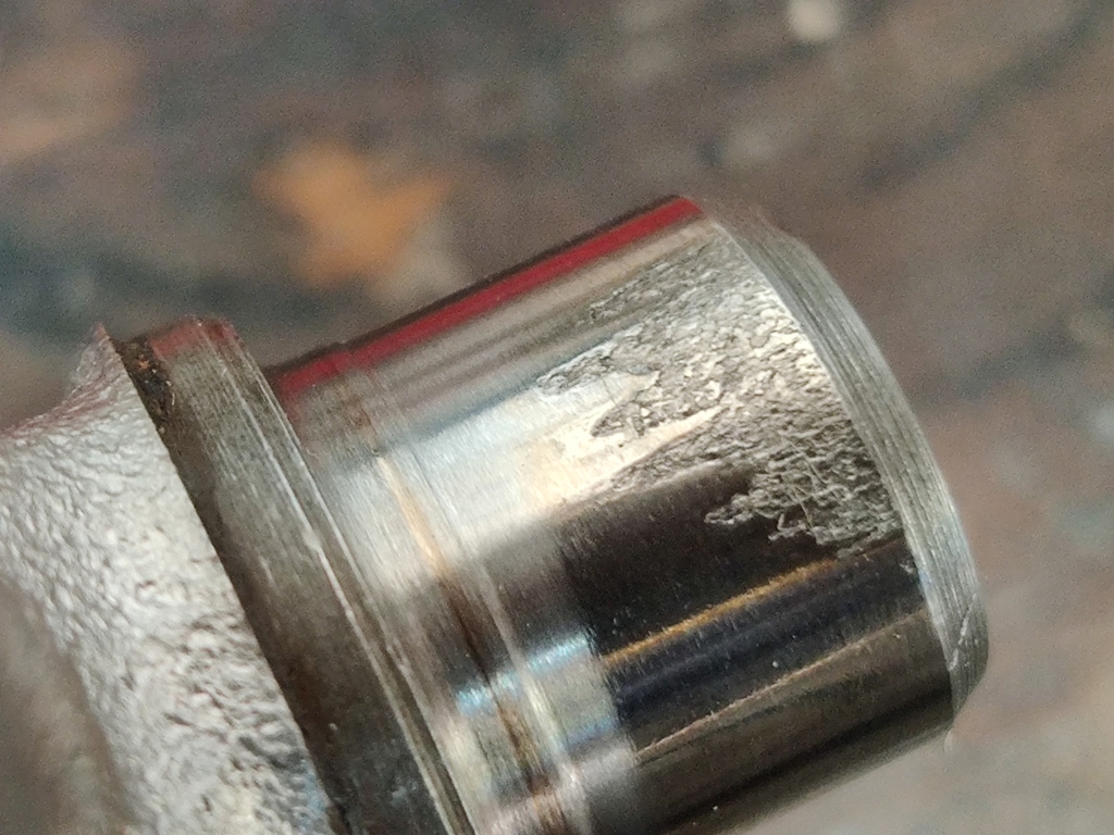
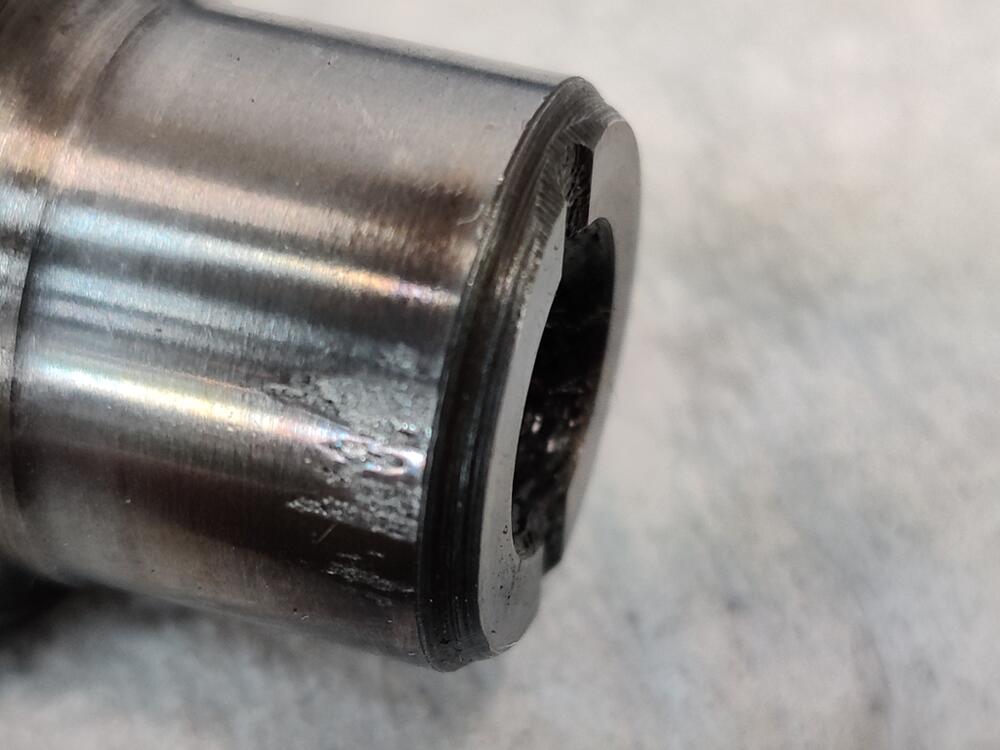
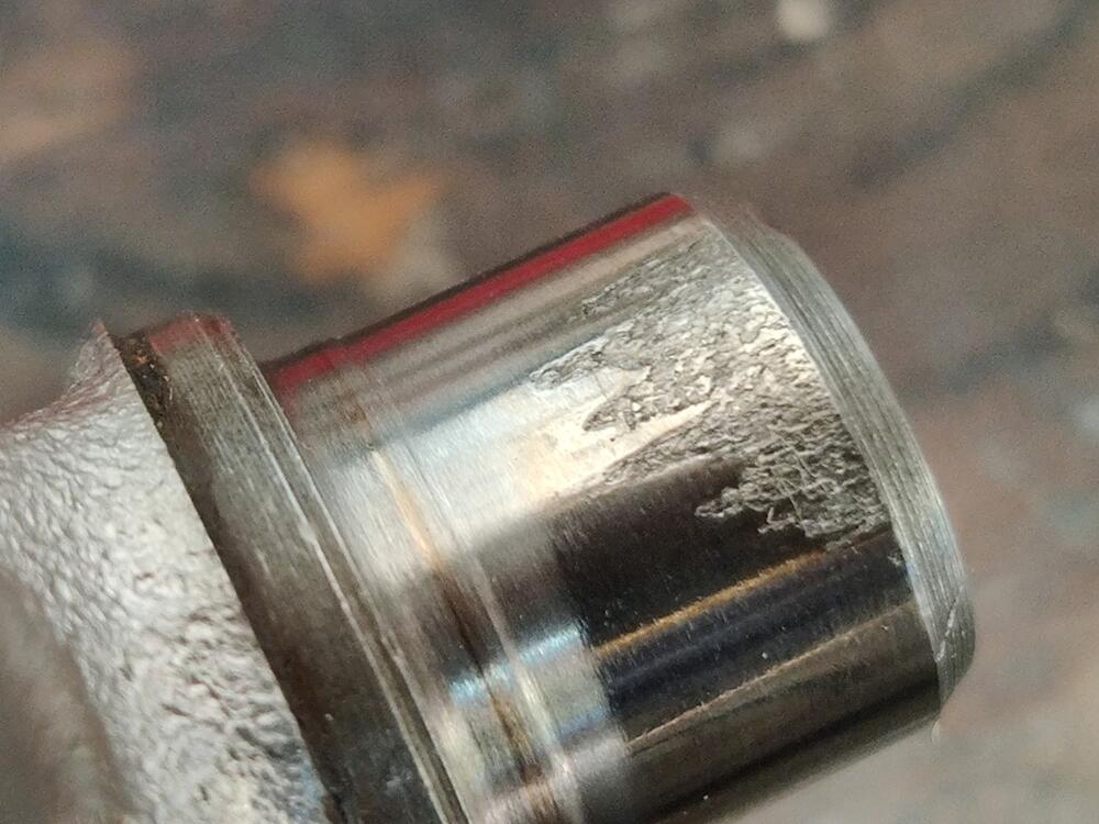
Well, I won't be attempting to drill them because I found a small amount of pitting on the surface of the journals when I took the u-joints out to inspect them. Time to replace them. Inner u-joint... and outer u-joint for one axle:
-
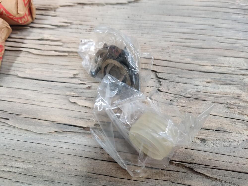
I removed and examined the u-joints from one axle. Even though they felt very nice, when I took them apart, I found some damage. First pic - outer joint, second pic, inner joint, and third pic - oem new in box joint: The new, oem joint is pre-drilled for a grease fitting but comes with a screw/cap, and retaining clips with different colors painted on their sides. They differ in thickness, with 3 or 4 groups of four clips. I think 12 total are included. I wonder if this casting mark (the I) is important (first pic)? The "D" location corresponds to the drilled hole for the grease fitting. I had two oem nos joints in my stash. Since both of the joints in the one axle I took apart had damage, I went ahead with ordering two more. I found some nos oem of the same part number on eBay for about $50 each. I need to review the what the factory shop manual says about replacing these u-joints to make sure I am not missing something important about the replacement process.


-
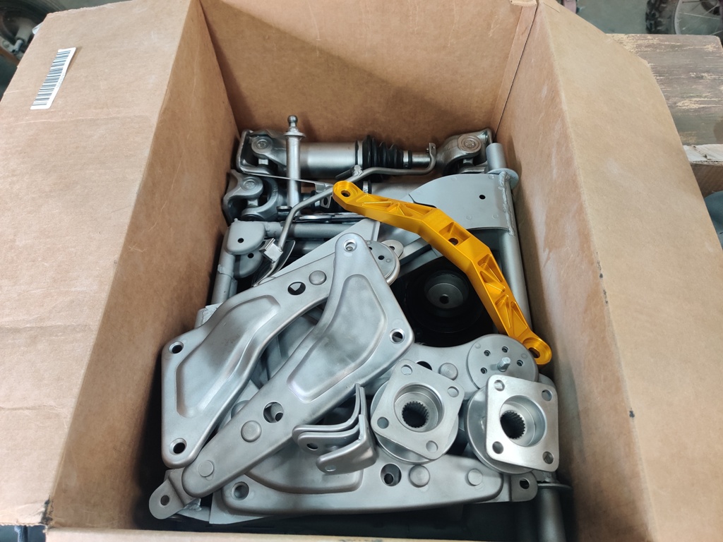
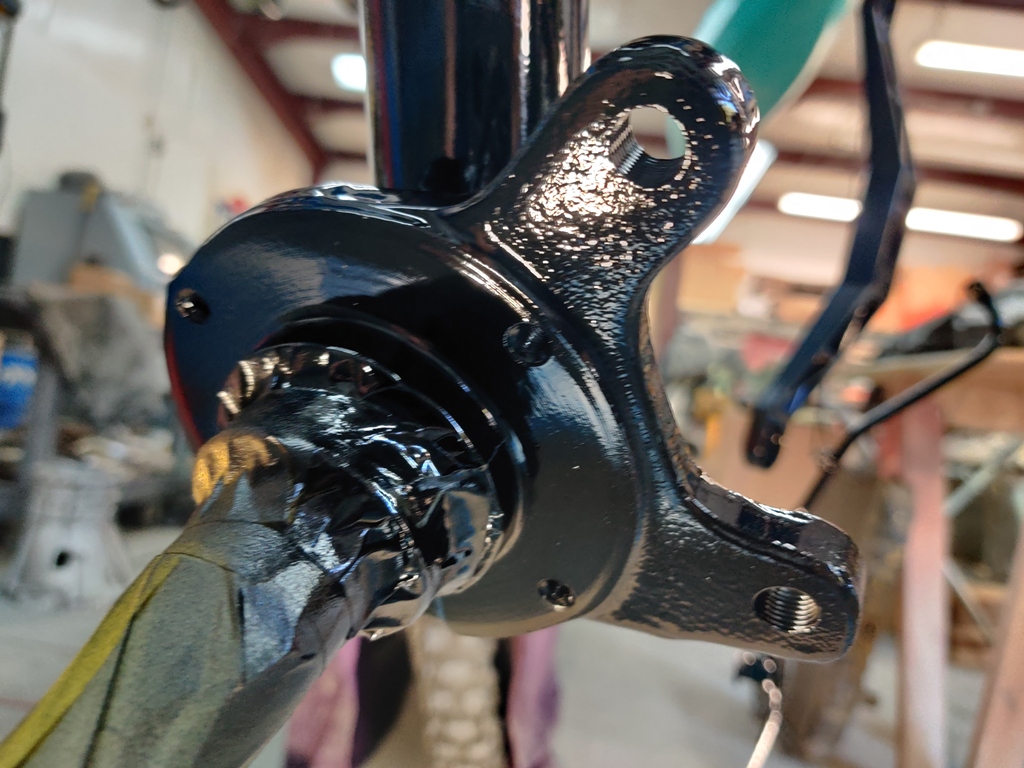
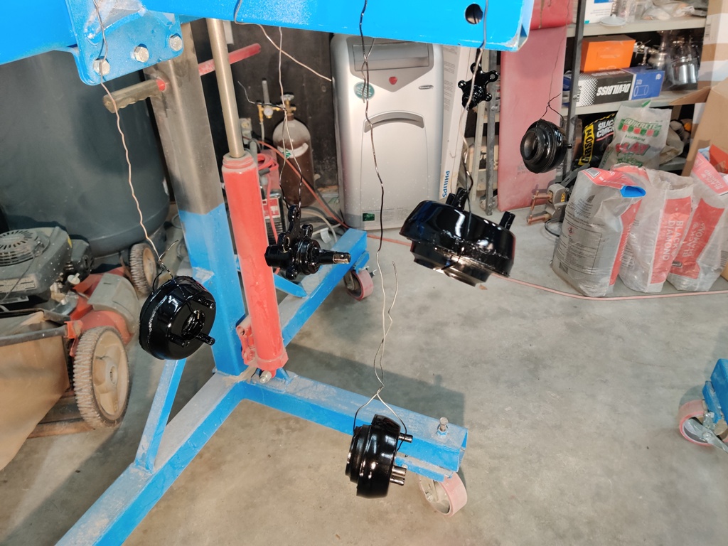
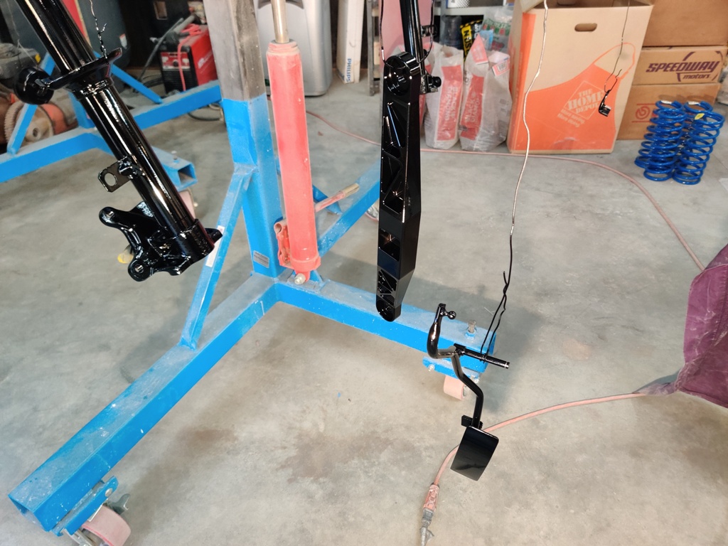
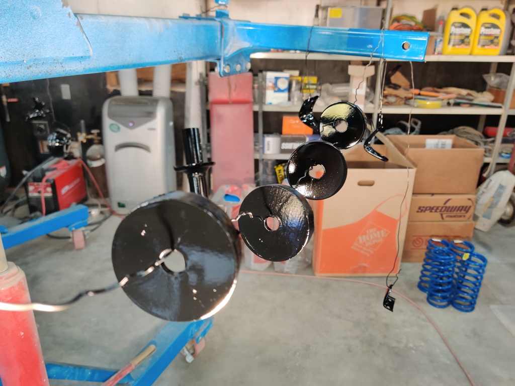
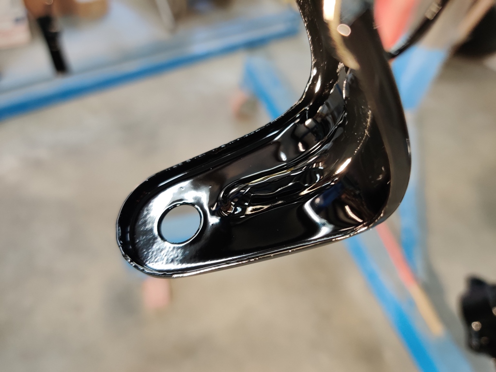
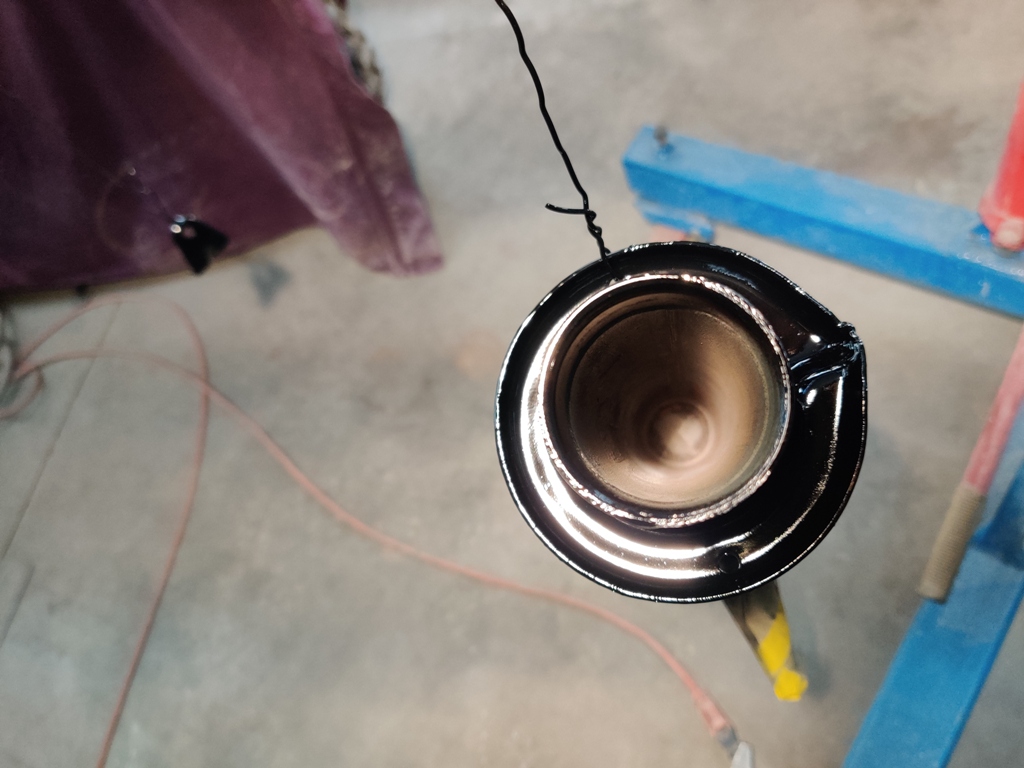
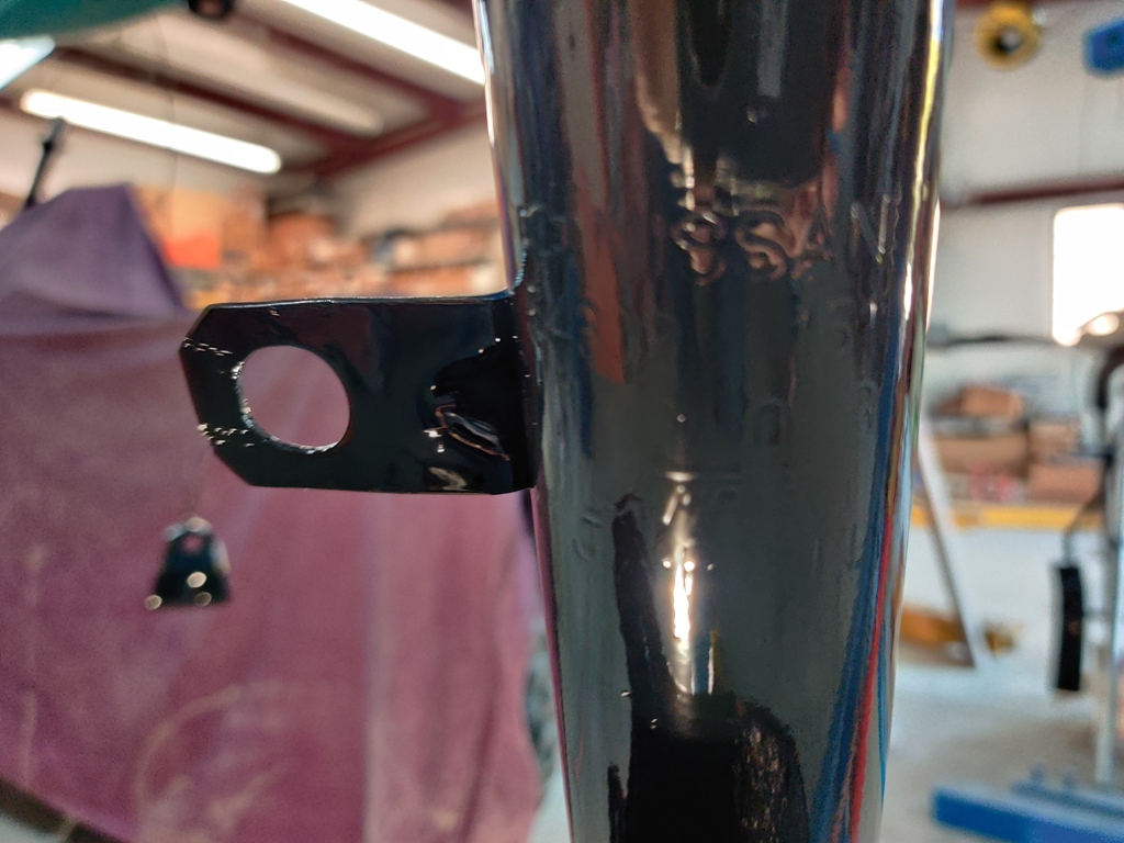
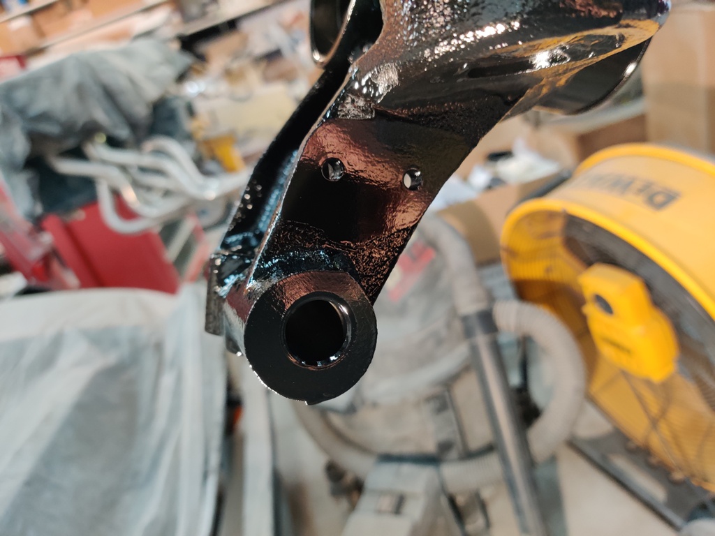
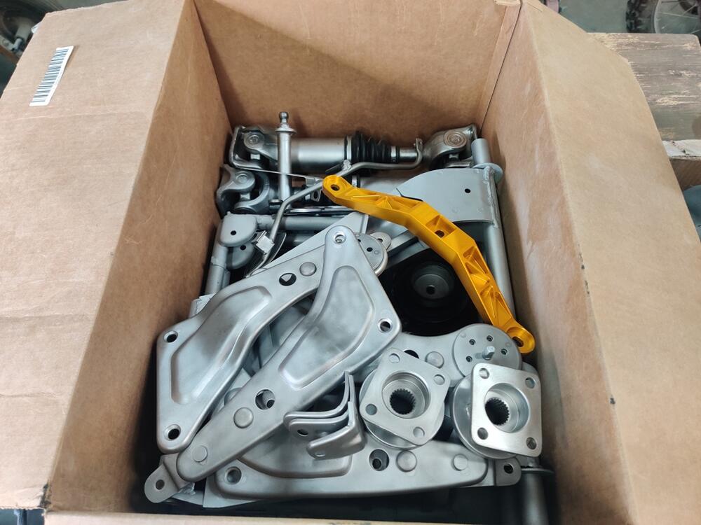
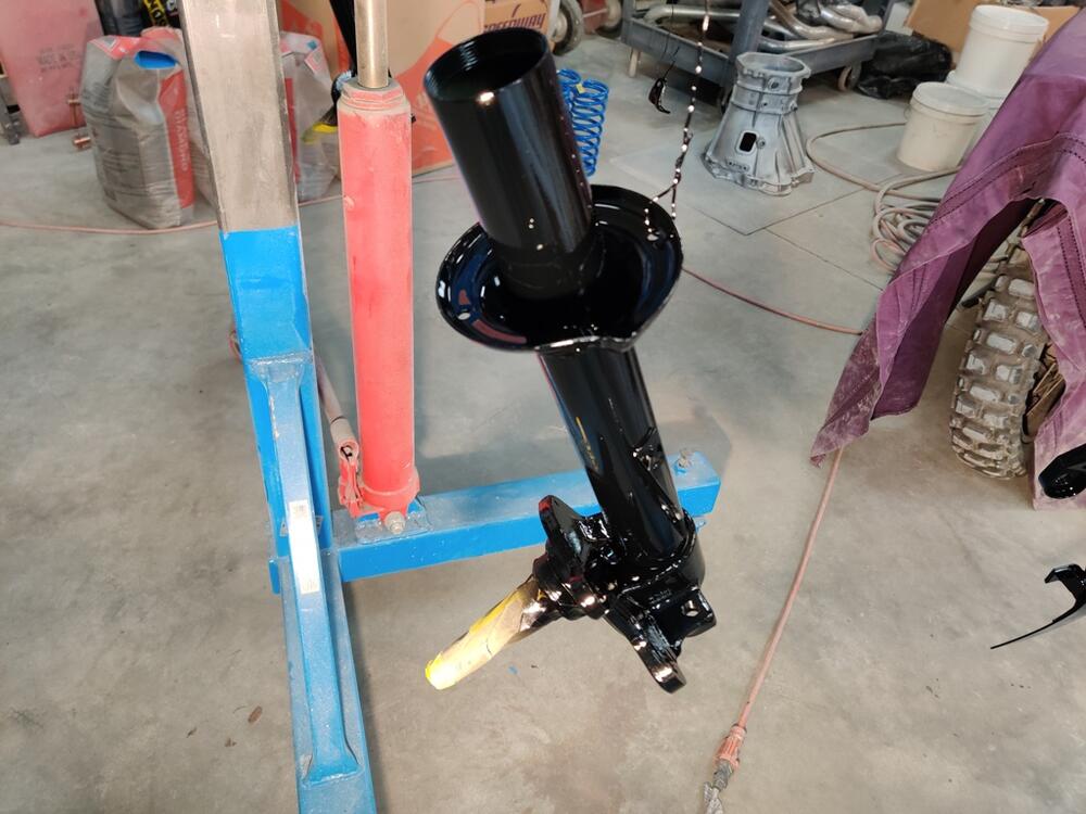
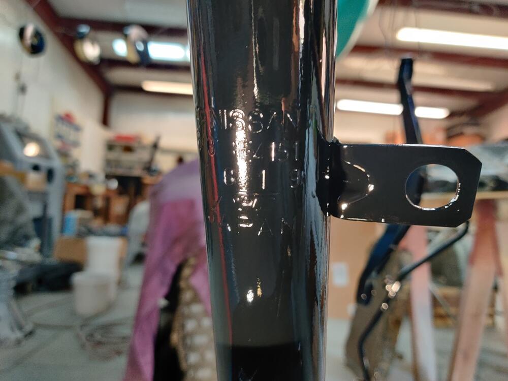
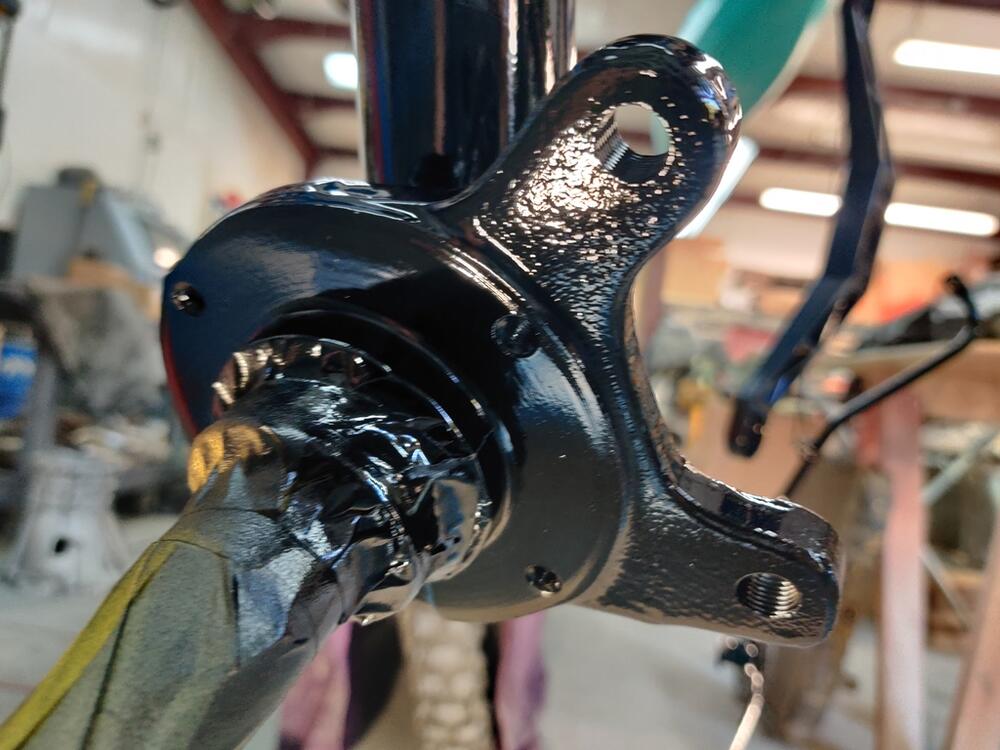
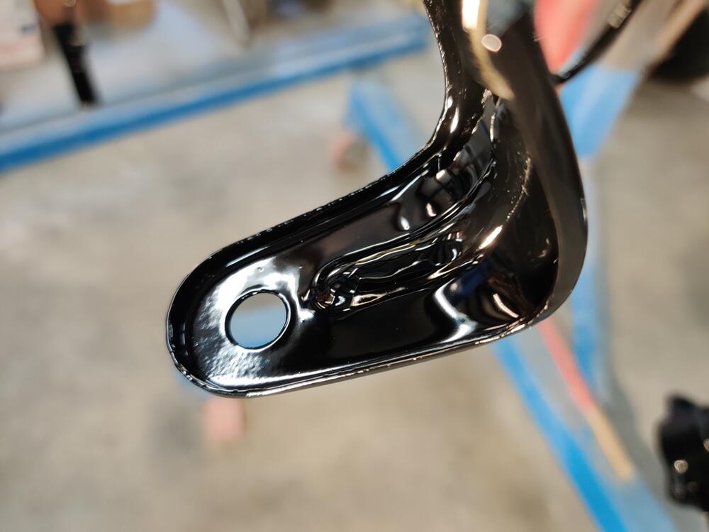
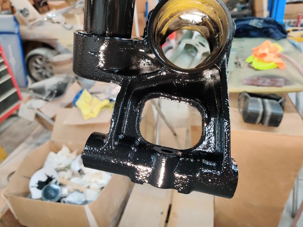
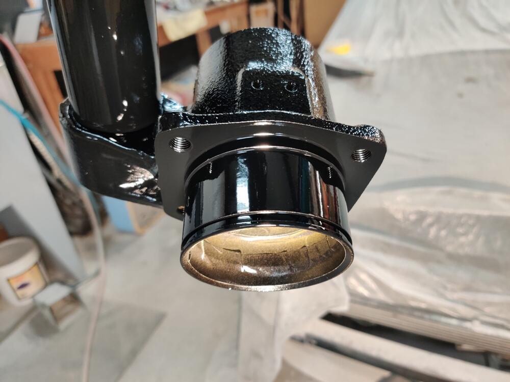
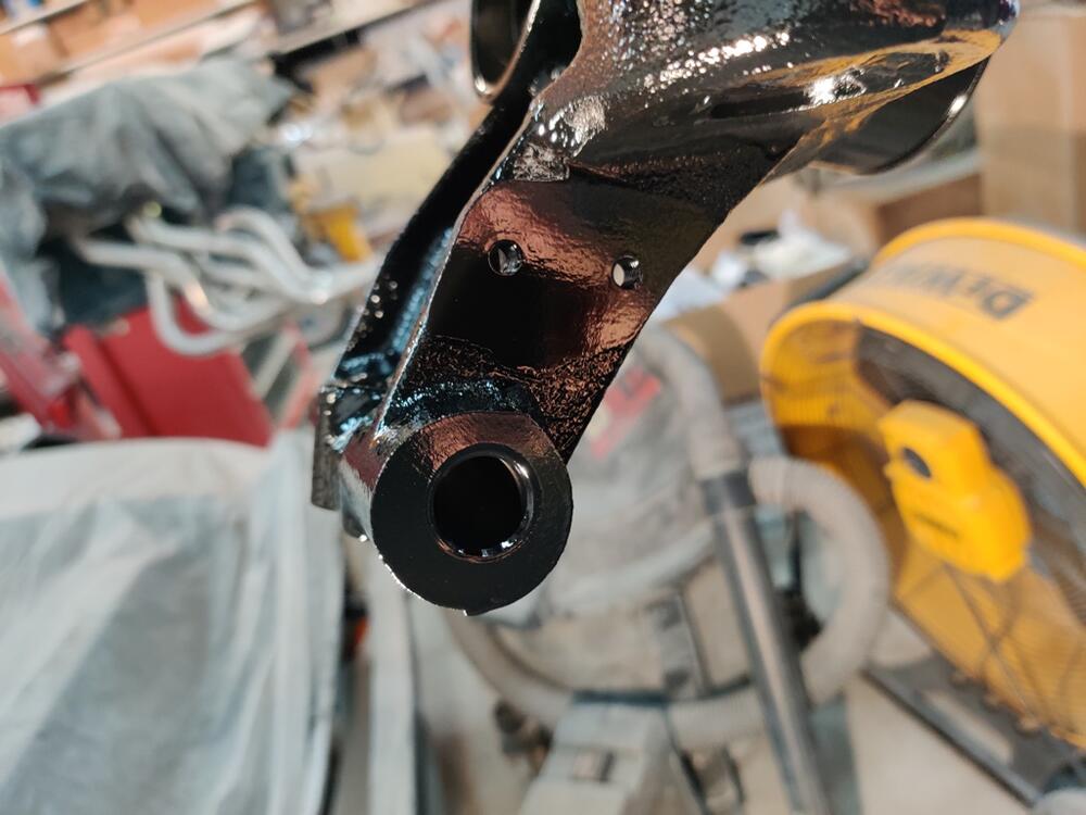
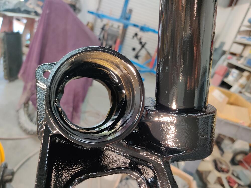
I have made some more progress with bead blasting (after coal slag blasting), and priming and then painting of black parts. I am really pleased with how these are turning out. First pic: Gold in a sea of silver - that is the T3 transmission crossmember for installing the 240SX transmission. Second pic shows brake hose bracket repaired on one of the front struts. Third pic - the rotisserie makes for a nice place to hang parts for painting. Front strut: T3 crossmember, gas pedal, rear mustache mount washers, dash vent bracket: Other front strut: Rear strut: Other rear strut: I am about 2/3rds of the way through the black parts. The nice thing about getting these done is that I can move on to some more of the assembly part of this process. No word from the painter about work begun on the car. Still waiting for paint sample cards.


-
Where is your neck of the woods out of curiosity? I use my press quite a bit, so getting a 20T to replace my 12T seems like a good idea at this point.