Captain Obvious
Free Member
-
Joined
-
Last visited
Everything posted by Captain Obvious
-
 Welcome to the club! Flat tops rule! Is that your 2002 as well?
 -
I don't like the whole "shared hold down" thing between intake and exhaust. It's what we got, but I just wish they hadn't done that. Hopefully Pacesetter can hook you up.
-
So I found a chunk of stock that would probably work for a crank nut. It's not as thick as I would have liked, but it's what I got. However, before I got too deep into it, I wanted to verify measurements: I'm going to make the ID to be a slip fit over a 1.378 shaft. Couple thousandths over. You had previously mentioned that the key is .205 wide? I'm thinking "as long as the slot is wide enough that the device fits over the key, it will work". The goal would be to keep the amount of slop to a minimum, but since you're just using it to turn the crank, it really doesn't matter. There could be 5 degrees of slop and it would still work, right? I'm thinking you'll want to rock the force back and forth to get the motor unstuck, so slop like that would be "uncomfortable and feel cheap", but it would still work. So how about the DEPTH of the slot? How far out of the crank does the key stick up? And we already talked a little about the flats on the outside for using a wrench. Would just two flats on opposing sides work for your BFA? That would be the easiest to make. Square would be second easiest. And I could do hex, but it's just more work.
-
Here's another thread for some input: https://www.classiczcars.com/forums/topic/62535-thick-manifold-washers-notched-wanted/
-
Wow. Me neither!! Hope those find good homes.
-
Glad to help. I'll take a look at what I have for raw materials around here and let you know.
-
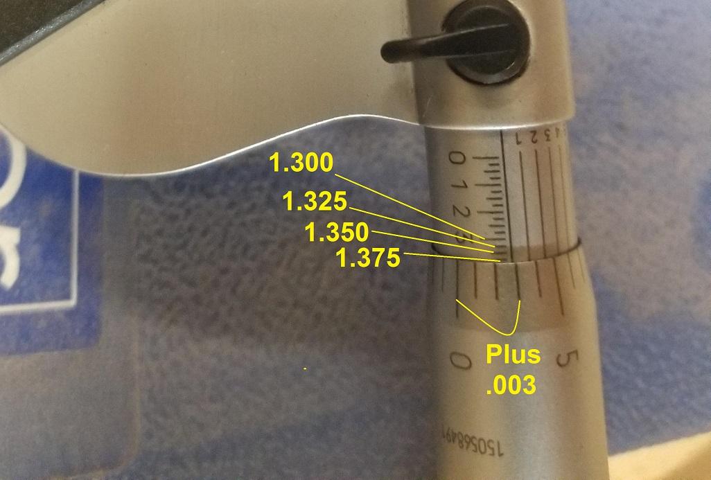
And forgot to mention... The other small numbers with the lines that run parallel to the thimble are vernier lines to estimate between the other lines. So since your .003 doesn't line up exactly with the fixed line on the sleeve, you could use the vernier lines to get one more digit of accuracy. You are alllllmost at 1.378, but an RCH below that. Eyeballing it, I estimate it to be a tenth of a thousandth smaller than 1.378, or 1.3779. You can't see it around the back side of the mic in the pic, but I bet the small "9" line is lined up-ish with one of the marks on the thimble. But for what you're doing, we don't need to split thousandths. 1.378 is good enough for me. (As a side note... 35mm is 1.37795 inches)
-
OK. I thought it might be aluminum. I know I found a bunch of aluminum ones when I was searching around, but wasn't sure if that's what you had. As for the micrometer... You got most of it right. It's a 1-2 inch mic, so yes, it's 1+something. And yes, the numbered hash marks make it 1.3 something. And yes... The un-numbered hash lines are each 1/4 of the major hash lines But since each of those minor hash lines is 1/4 of .100, it works out to twenty-five thousandths (.025). And as you turn the thimble (the part that spins), you are counting up thousandths to add to the previous .025 hash mark. So if the zero on the spindle lined up perfectly with the third minor hash line, you would be at 1.375 (1.3 + .075). But you're actually three thousandths beyond that 3/4 hash mark, so you have to add three more thousandths. 1.375 + .003, or 1.378 I whipped this up to hopefully help:

-
I get 1.378 OD off that mic (not 1.373). So it looks like that crank snout is 35mm. So the one you ordered from Summit looks like aluminum? That would be easier for me to work with. Wouldn't last as long, but certainly easier to produce.
-
Well if you're hitting the brakes and the RPM's are going up, then that's most often an indication of a leak somewhere. And most often that is a hole in the booster diaphragm. So are you sure that when you actuate the booster and hold the pedal position constant, it doesn't continuously bleed off your vacuum on the bench?
-
Yes... 2% of the hole. Considering the hole (nozzle) to be 0.100 inches diameter, the "whole hole" area would be 0.00785 square inches. The difference in the amount of the hole open for fuel flow is 2% larger using a .094 obstruction as opposed to a .095 diameter obstruction. As far what the direct impact is on richness, I don't know. I doubt it's a simple calculation and don't know if it could be modeled easily. In other words, the area calculations are easy... The exact IMPACT on the bottom line (mixture ratio) is beyond my pay grade.
-
Right. The slope of the taper (rate of change) may be different across the stations, but it's always a "slope" and not a step. Looking at the .095 vs .094 example above in a different way: If the needle is .095 and is in a .100 hole, you have 90.25% of the hole filled up (with needle) and you have 9.75% of the available area open to fuel flow. Changing the needle diameter to just .094, you have 88.36% of the hole filled which results in having 11.64% of the available area open for flow. So changing just one thousandth like that results in an approximate 2% increase in the area available for fuel flow.
-
So who is Aitoku? Is that supposedly the company that cast the valve covers? Seems weird to put that label on it that talks about making sure you have oil. "NOT INSTALLED ANY OIL ON THIS ONE!" Like someone bought a valve cover from the local Nissan dealer 35 years ago with the intent of making it a show piece or collectors item? Who does that for a car that's only ten years old? The labeling just makes it weirder.
-
There should be some decrease in the vacuum on pedal push, but I would expect there to be more on pedal release. As long as it doesn't continue to bleed out when you hold the pedal push constant, then I don't think you have a leak in the booster diaphragm. I'm no booster expert and I hope I'm not coming off as one, but from my looking at the design, I believe that's the case. The whole thing is actuated by a pair of valves on the pedal shaft. With the pedal not pressed, it opens a valve between the two sides of the diaphragm and allows vacuum to build and equalize on both sides. Then as you press the pedal, the first thing that happens is it closes off that valve between the two sides. Then as you continue to press further, it'll open up a second valve to vent off some of the vacuum on the rear side. What I'm trying to test with the "set amount" of vacuum bleed on pedal push is... Does that "close before open valve" work properly and are there no other parallel paths between the front and rear sides of the diaphragm (like a hole). I'm trying to come up with scenarios that you can look for on the bench that give you some confidence in the operation. "Holds vacuum indefinitely while static" is a good first start. "Goes whoosh when you press the pedal" is a good second test. "Drops a set amount, but not all the way when you press the pedal" is a good third test. if it passes all three of those I expect it's good enough be worth the time to install it and give it a try.
-
I think as long as it depletes a set amount, the diaphragm is intact. The "set amount" thing is promising. From what I can tell (from a distance and all that) it sounds like a good booster. How much vacuum are you able to draw down on it? Hand pump, or you got something powered?
-
Yeah, that's what I figured. I didn't think the inside would be coated. Even if they did coat the outside, I would guess they were less worried about the inside. Not only the because you can't see it and they don't care as much, but it's also in an oil bath. So the real question is... Is that silver paint factory, or was it applied by someone else in the past? I don't really like the look of the sealant on the PCV baffle cover on the inside either. And the soft corners on the machined bottom surface. The ones I've messed with were machined and barely deburred. You could still slice open a knuckle if you caught that edge wrong. Yours looks like it had sandpaper run along it to soften the corners. I do that when I work on stuff, but the factory usually never does. Wish I could help more. I really don't know.
-
Good. Wait... Not good. You know what I mean. So your nut will work. Too bad about the front cover.
-
Oh, and I forgot this!!! >>>
-
I believe it's simply ID and OD. The small change might seem immaterial, but I bet it's quite significant if you look at it in percentages.
-
Well there's lots of ways that a booster could go bad, but that's one of them. If you vacuum the booster down and then stop pulling it down, it should hold that vacuum. I've gone to junkyards and pressed the brakes on a car that's been there for who knows how long, and sometimes you'll still get a whoosh or two because the booster still had vacuum in it. Check valve still worked and the valve built into the booster didn't leak. That said, another common way for a booster to go bad is for it to leak through the big diaphragm (like there's a crack in it or something). The reason I bring that up is because it will act almost like a working one on the bench with one detail... If you pump down a working booster and put a gauge on the engine side (the front side) it should hold that vacuum while not pressed. It sounds like yours does that. But as you actuate the booster, it should not lose much vacuum on the front side. It should stay pretty much the same. Then when you release the booster rod, it should bleed from the front side to the back side, and that's when you should see the vacuum change on the front side. Not on "pedal down", but on "pedal up". If you see all of your vacuum disappear immediately on "pedal down", then you may have a hole in the diaphragm.
-
Call me skeptical, but I'd be very surprised to hear that they painted the valve covers. Maybe, by some wild stretch.... Maybe someone could convince me that the very early valve covers got some paint, but by the time they got to the NISSAN OHC covers? I'm very skeptical. Frankie, Is the inside painted? Can you use the same solvent you used on the outside and see if anything comes off the inside? I do know (from unfortunate yellowing and peeling experience) that they clear coated the later valve covers. I don't know if they did that all along, but by the end, they were.
-
Oh yeah, I got caught up and forgot to tie that back to your question... The POINT is that every time you actuate the booster, you'll be "using up" some of the vacuum on the back side of the booster. And then when you stop actuating it and everything equalizes, it won't return to the same vacuum because you've vented some of it off. Every time you actuate it, you'll lose some of that vacuum.
-
The power brake booster basically works like this... 1) With no foot on the pedal, apply equal vacuum to both sides of a the big diaphragm. 2) Then when the pedal is pressed, allow some atmospheric air (from the car's interior) into the cavity on the rear side of the diaphragm (the side you sit on). 3) Allowing some atmospheric air into the rear side reduces the vacuum on rear cavity and allows the vacuum on the FRONT side to help pull the diaphragm towards the front of the car. 4) The further down you press the pedal, the more atmospheric air is allowed into the rear side and the more assistance you get from the vacuum on the front side 5) Then when you let off the brake, the vacuums equalize between both sides of the diaphragm again. Not that anyone asked.... * I know that it's pushed by the higher pressure and not "pulled" by the lower pressure, but I think it's easier to describe as being pulled.
-
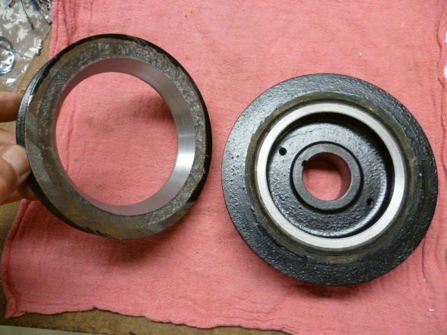
I'm looking at some old pics of when I cut one of the pulleys off a two-pulley harmonic balancer. (Academic project on a damaged balancer.) Don't remember if I ever posted these in the past, but here's a couple pics: The point is... I'm wondering if the nut you purchased is going to work. First, the corners of the hex need to be small enough to fit inside the front oil seal. You could remove the front seal if you need to (since you're probably going to replace it anyway). Second, you'll need enough length on the nut to a) engage the key on the crank, and b) still have enough length sticking out of the front cover to get a turning tool onto it. If the front cover is completely off the motor then neither of those trouble spots apply, but if the front cover is still installed, I'm thinking things might not work out.

-
You gonna be OK? Need anything?