


Namerow
Free Member
-
Joined
-
Last visited
Everything posted by Namerow
-
 Don't forget to check the 'miscellaneous automotive parts' display rack at your local Canadian Tire store. I'm pretty sure you'll find at least a couple of types nylon headlight adjuster sockets, and one of them might adaptable.
 -
I didn't know there were any fish left in Lake Erie! BTW, if you'd like to read some great stories about the trials and tribulations of life as an independent commercial fishermen (or 'fisher', as the CBC likes to call them), find a copy of ''Song of the Sirens" by Ernest Gann. Congrats on your retirement.
-
My ashtray suffered from exactly the same problem (design flaw). I rebuilt it and the results came out quite well. If you're unable to find a replacement unit and you're interested in giving it a try, let me know and I'll post some pictures of the rebuild.
-
Ashtray lid and Heater control knobs available at http://www.240zrubberparts.com .
-
Looking forward to your latest notes. I'm still not getting the results I'd like.
-
Watchmaker, no.... although there were a lot of slot cars and Revell and AMT model kits back in my youth -- many of which featured poor attempts at highlighting the trim with silver paint and a 000 paint brush. I always wondered how this foil applique stuff worked, so I decided to give it a try. The trick to success is to drink the beer after -- rather than before or during -- the job . Wish I could get my zinc plating efforts to work out this well! BTW, the foil is stuck to the plastic pretty solidly and shows no signs of lifting or even being prone to lifting. It has about the same 'stick' quotient as aluminum HVAC tape (i.e. pretty good). Nevertheless, certain adhesives don't handle high heat, so we shall see. The piece that's of greatest concern is the console insert plate, because it's located in a 'busy' part of the interior and the foil lines are thin. I have no experience with Sharkhide, so not sure whether it would help or not. For absolute protection, a coat of epoxy matte clear would seem to be the right way to go.
-
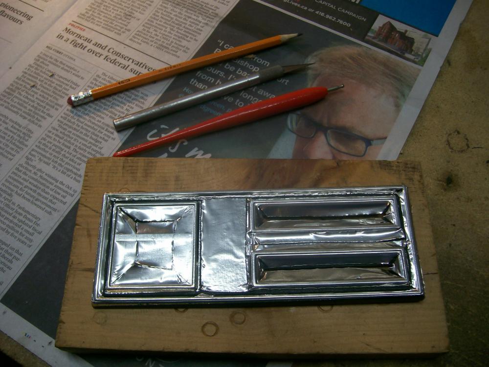
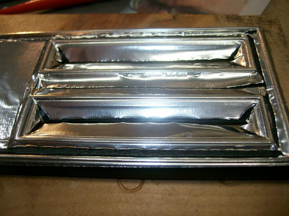
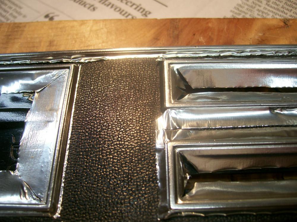
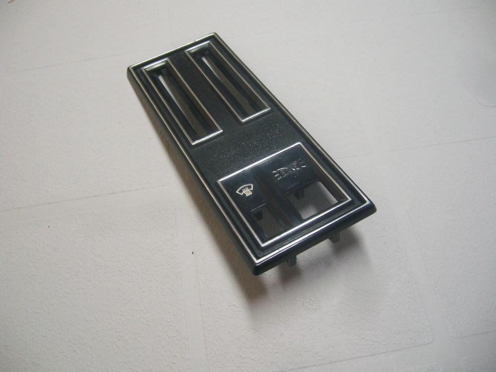
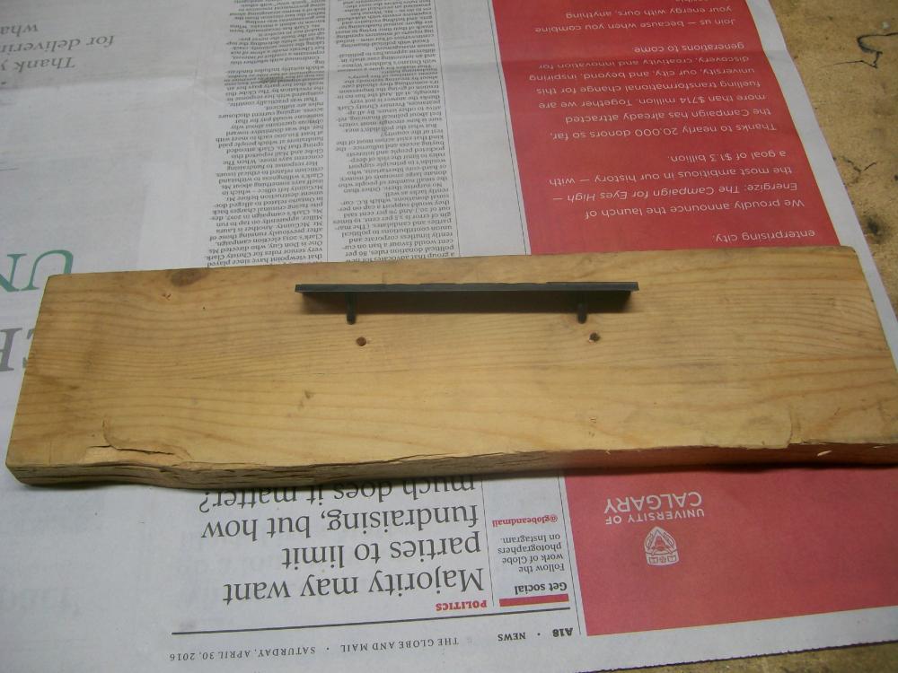
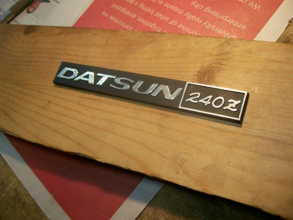
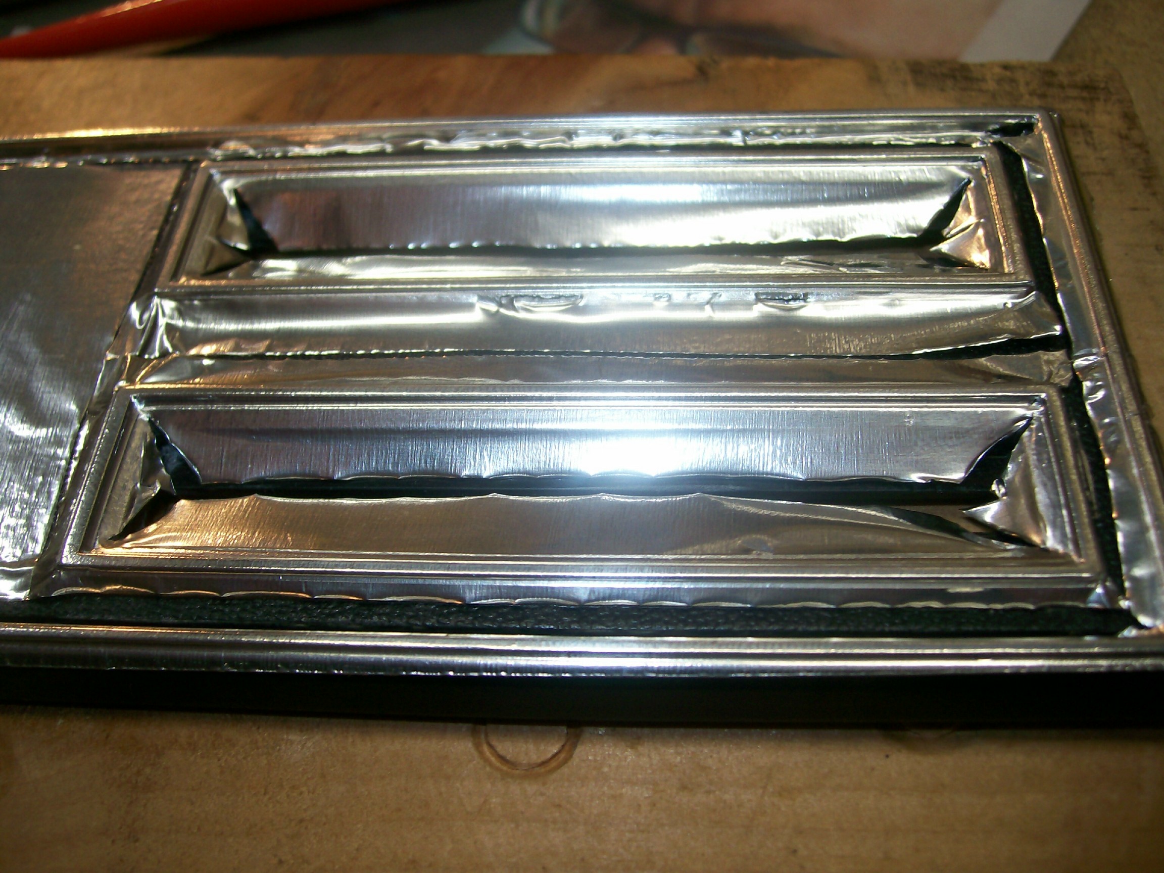
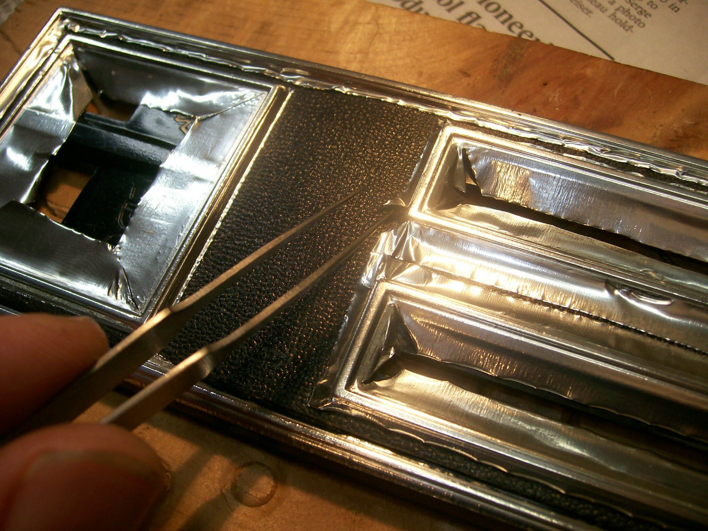
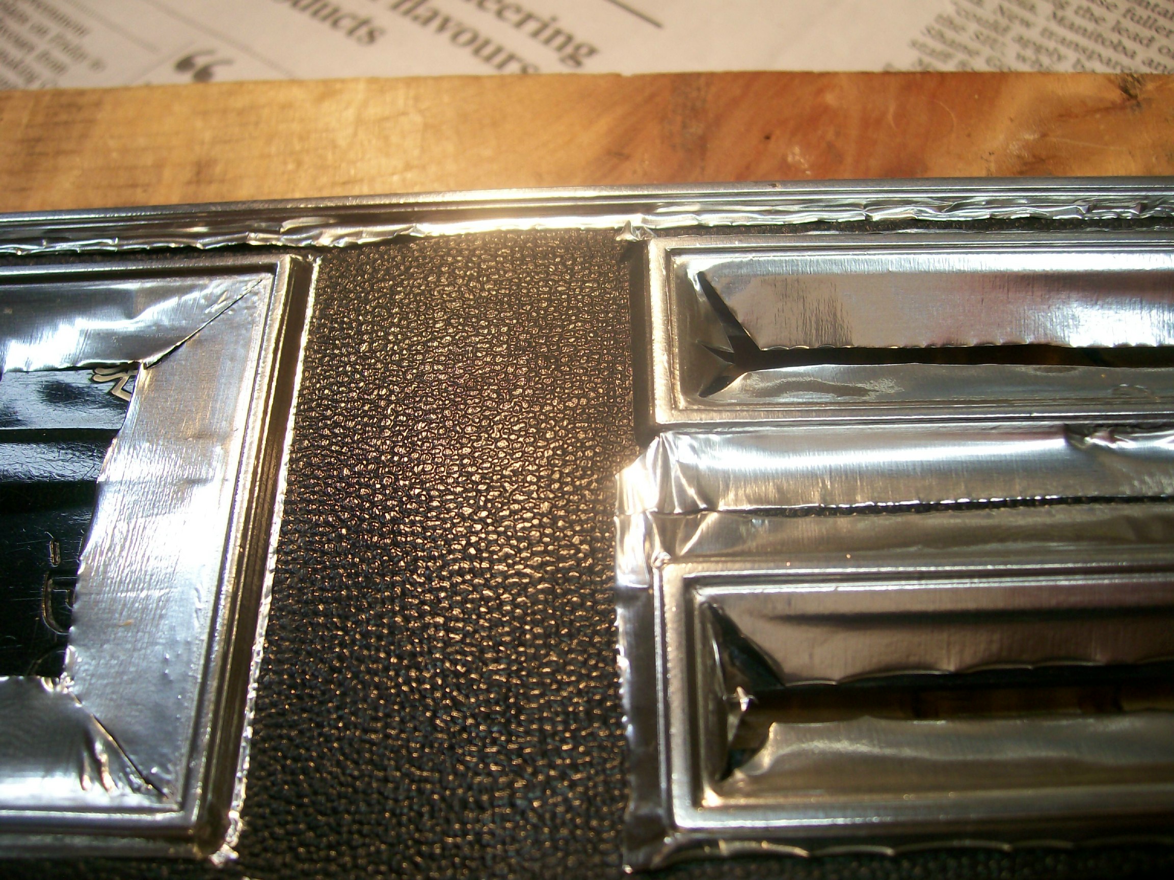
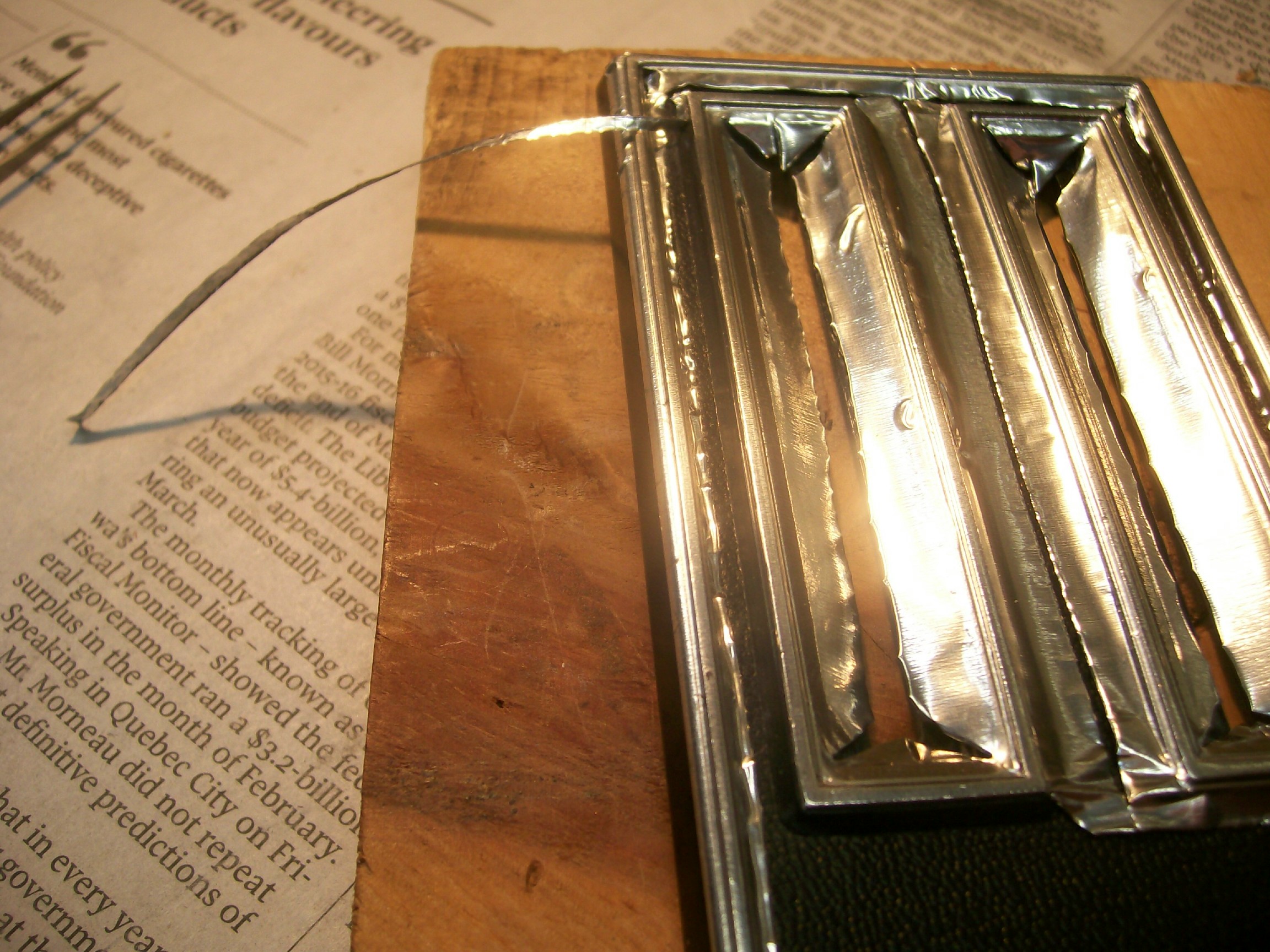
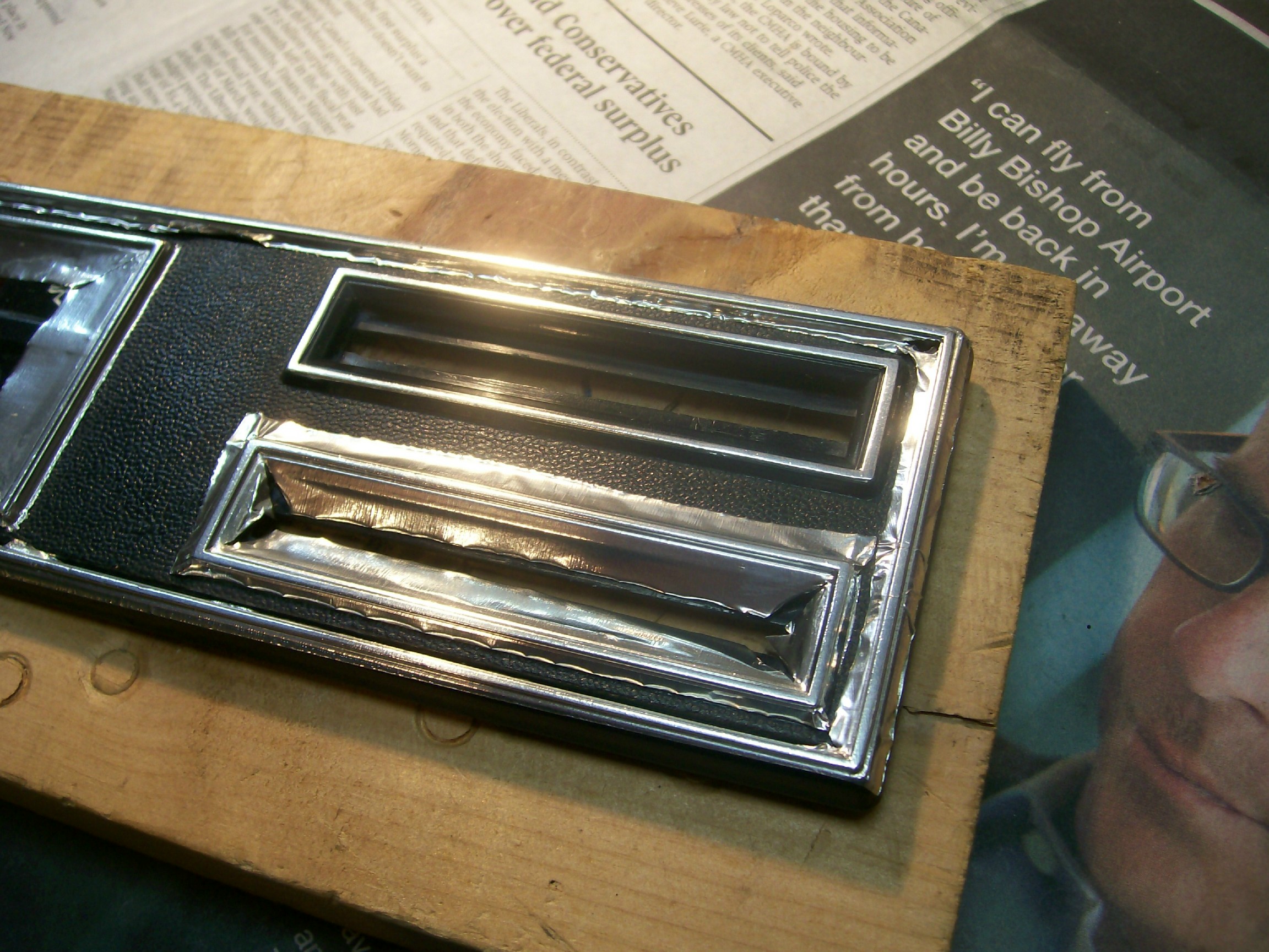
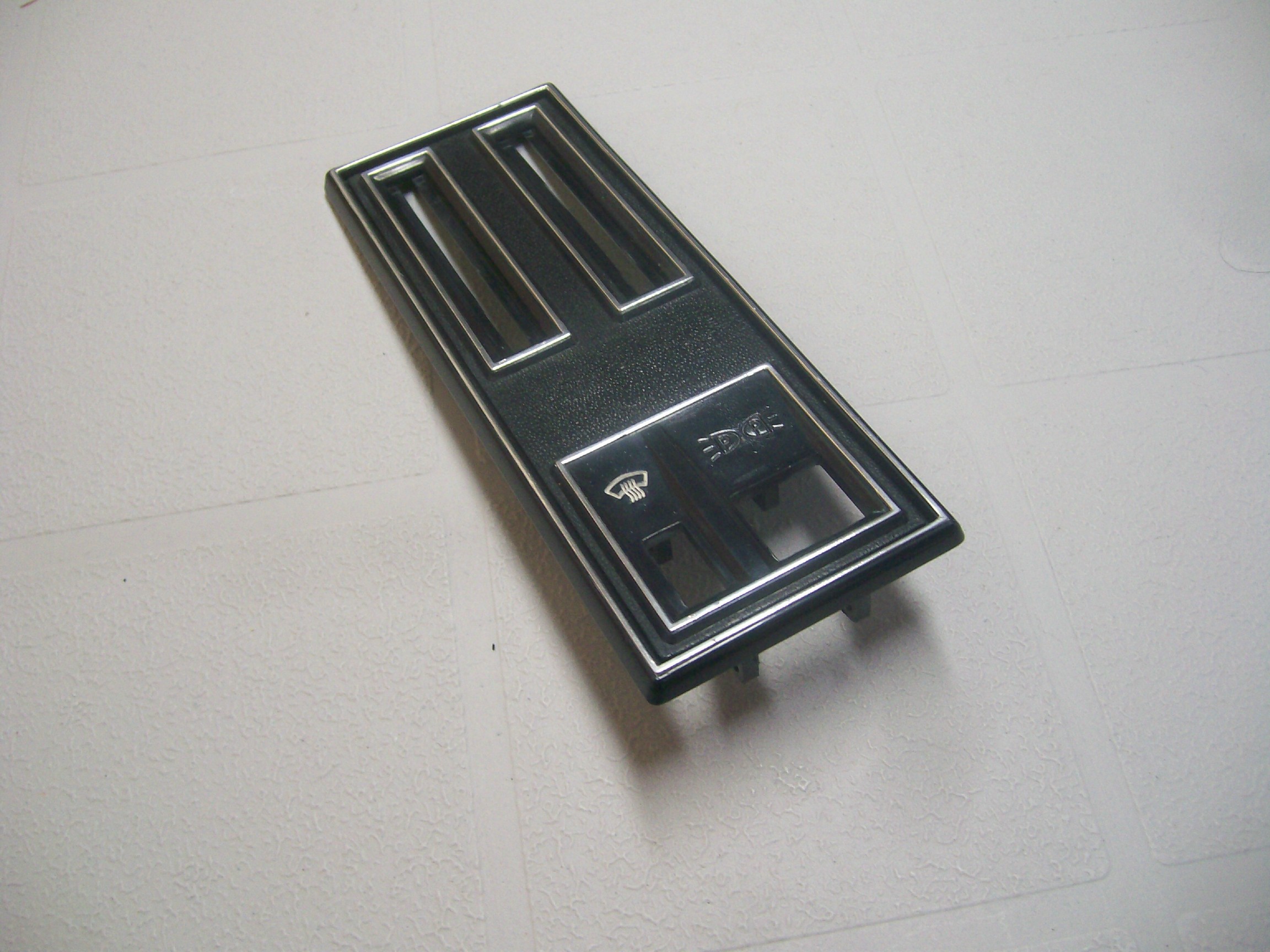
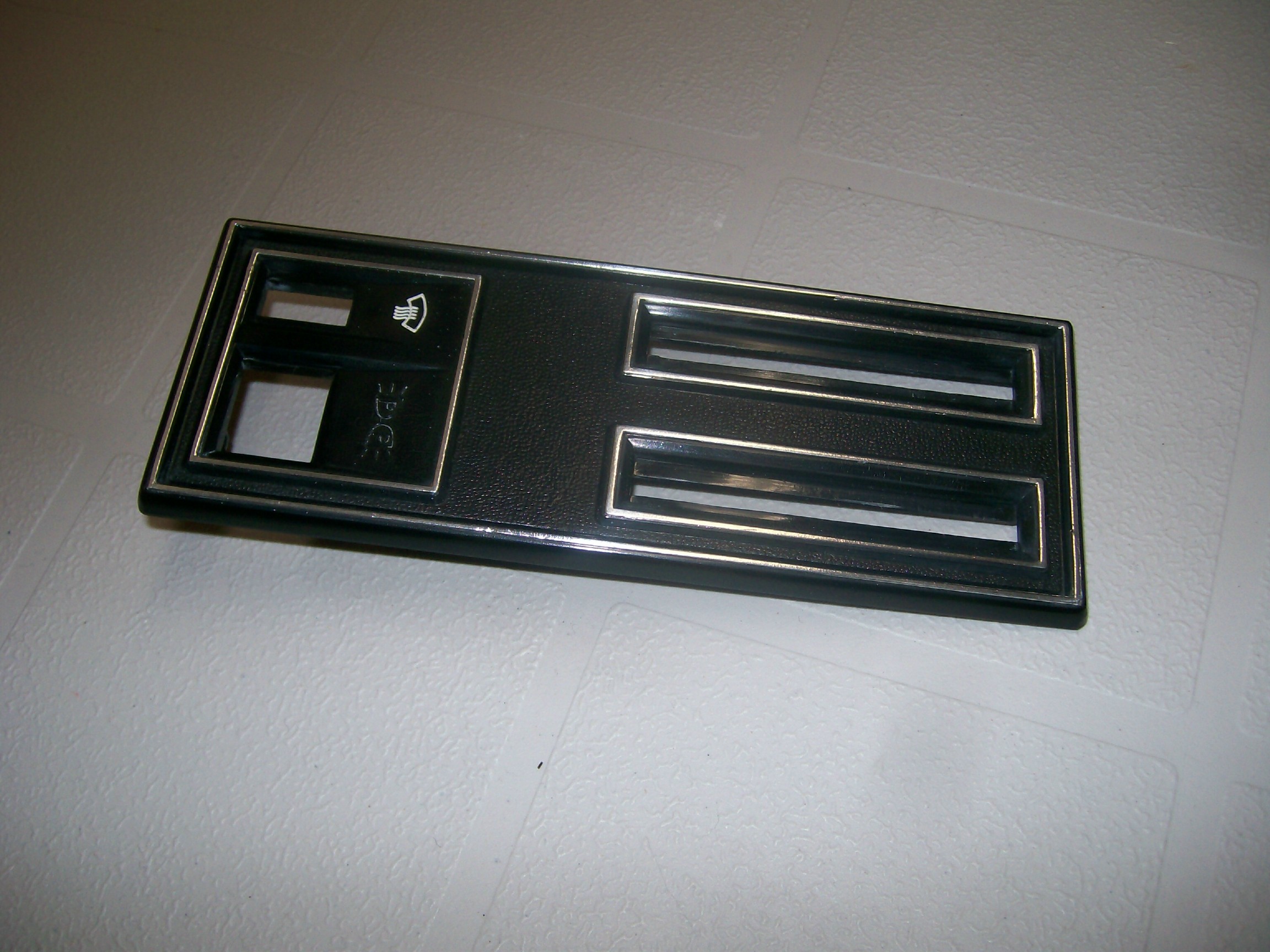
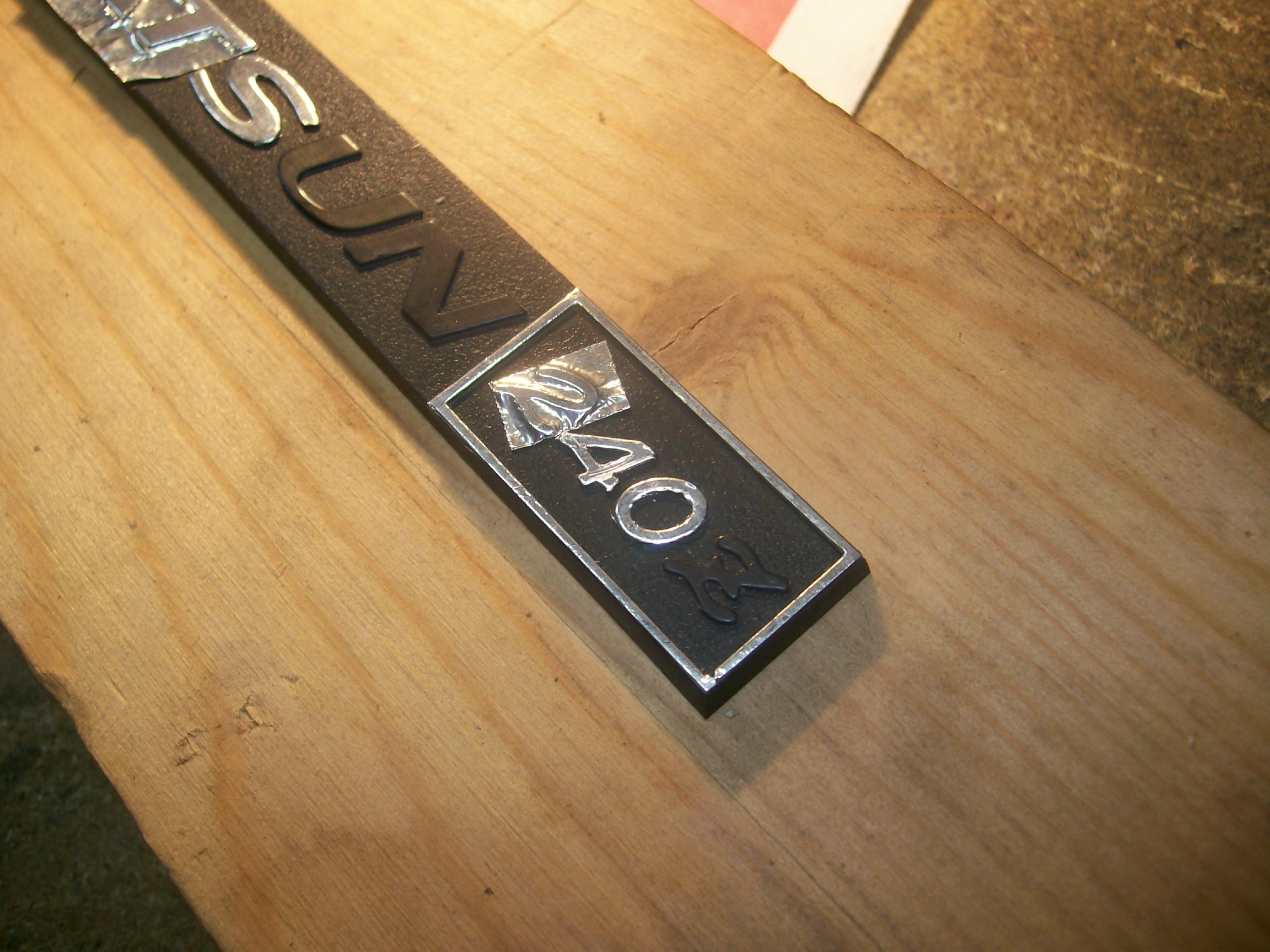
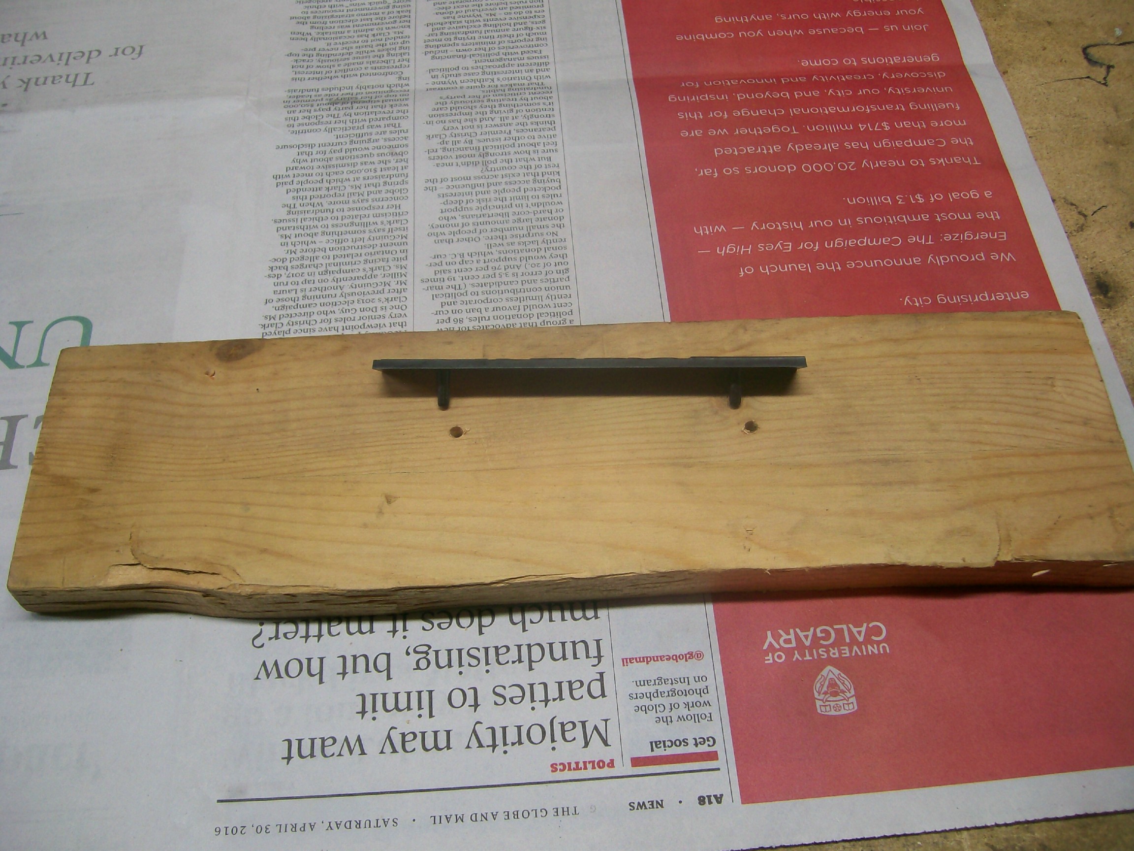
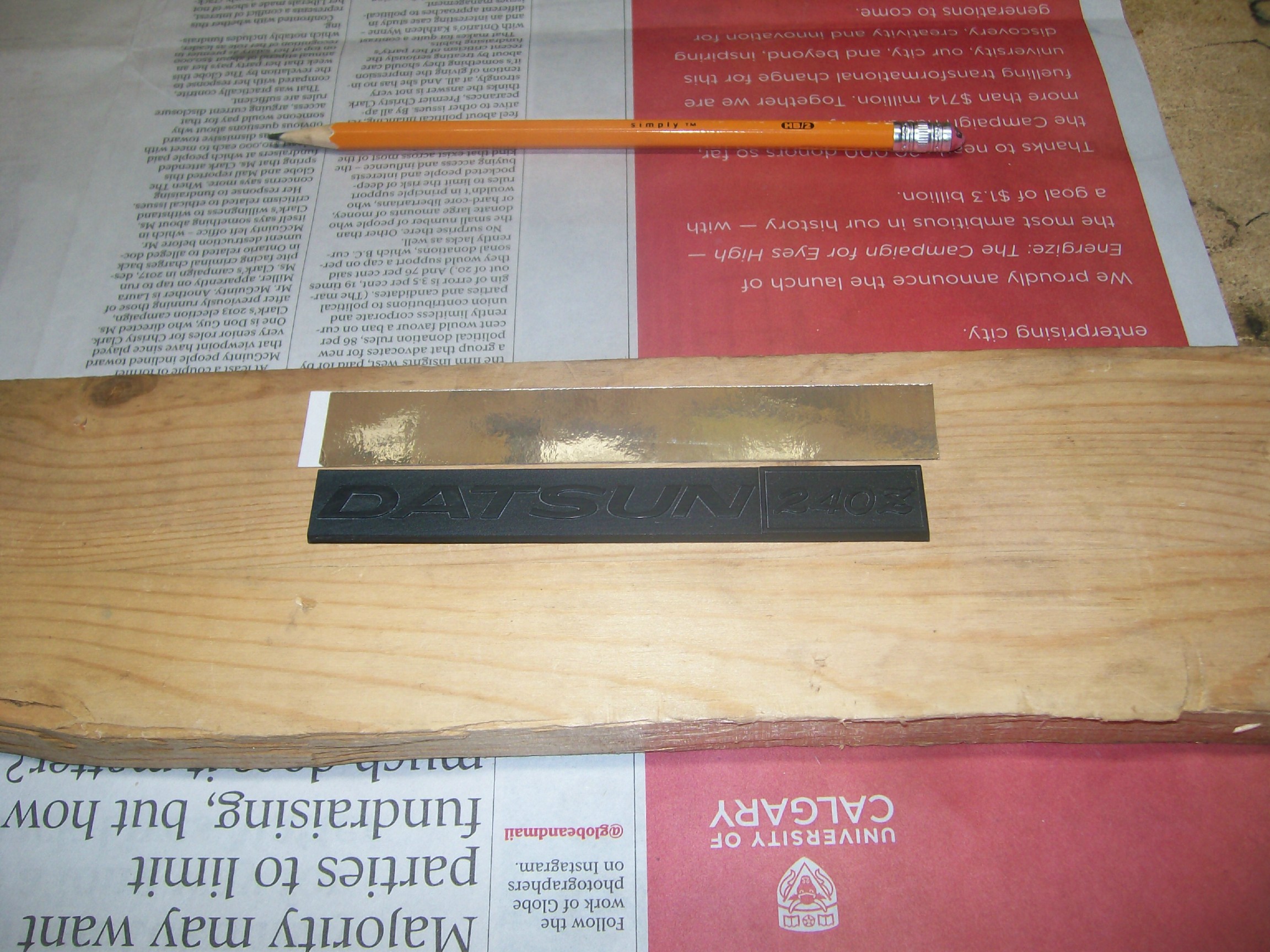
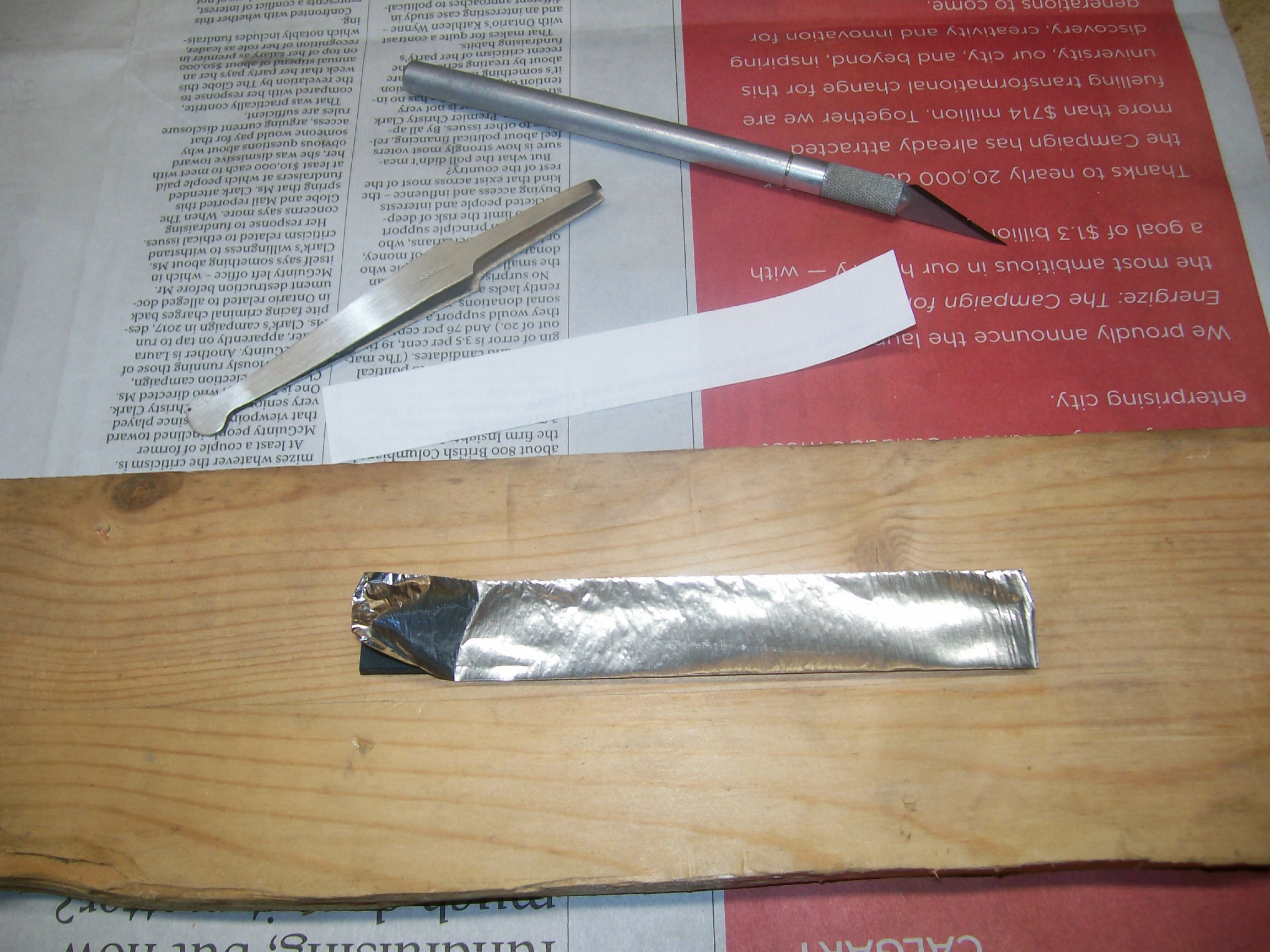
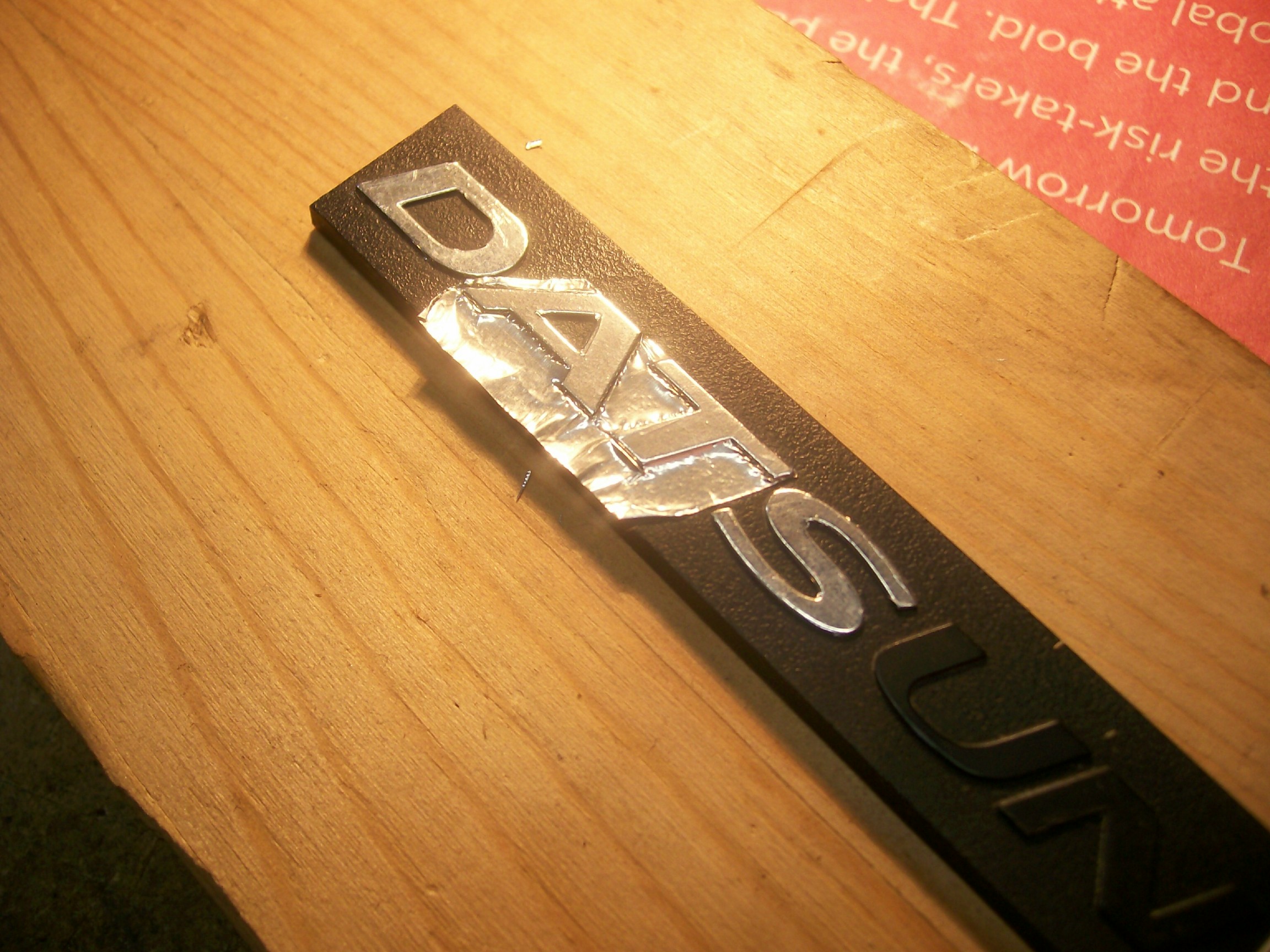
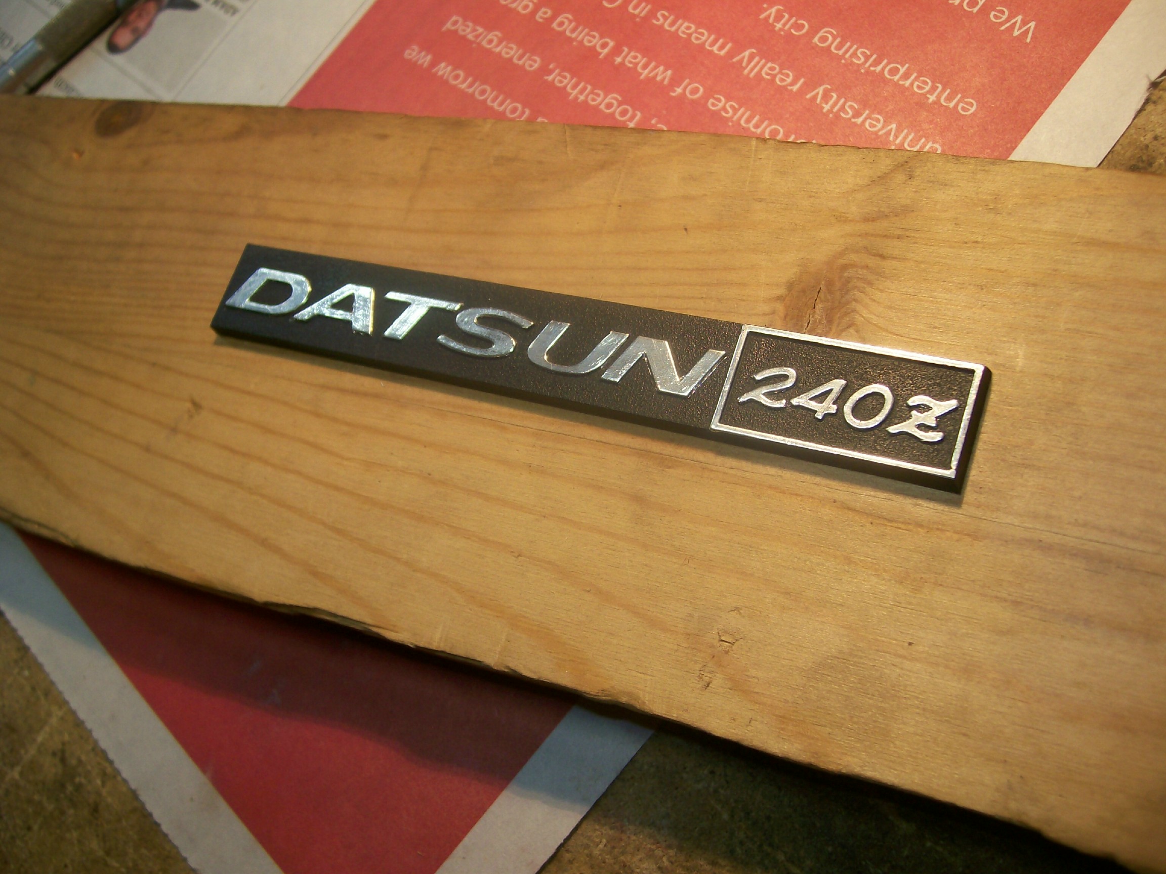
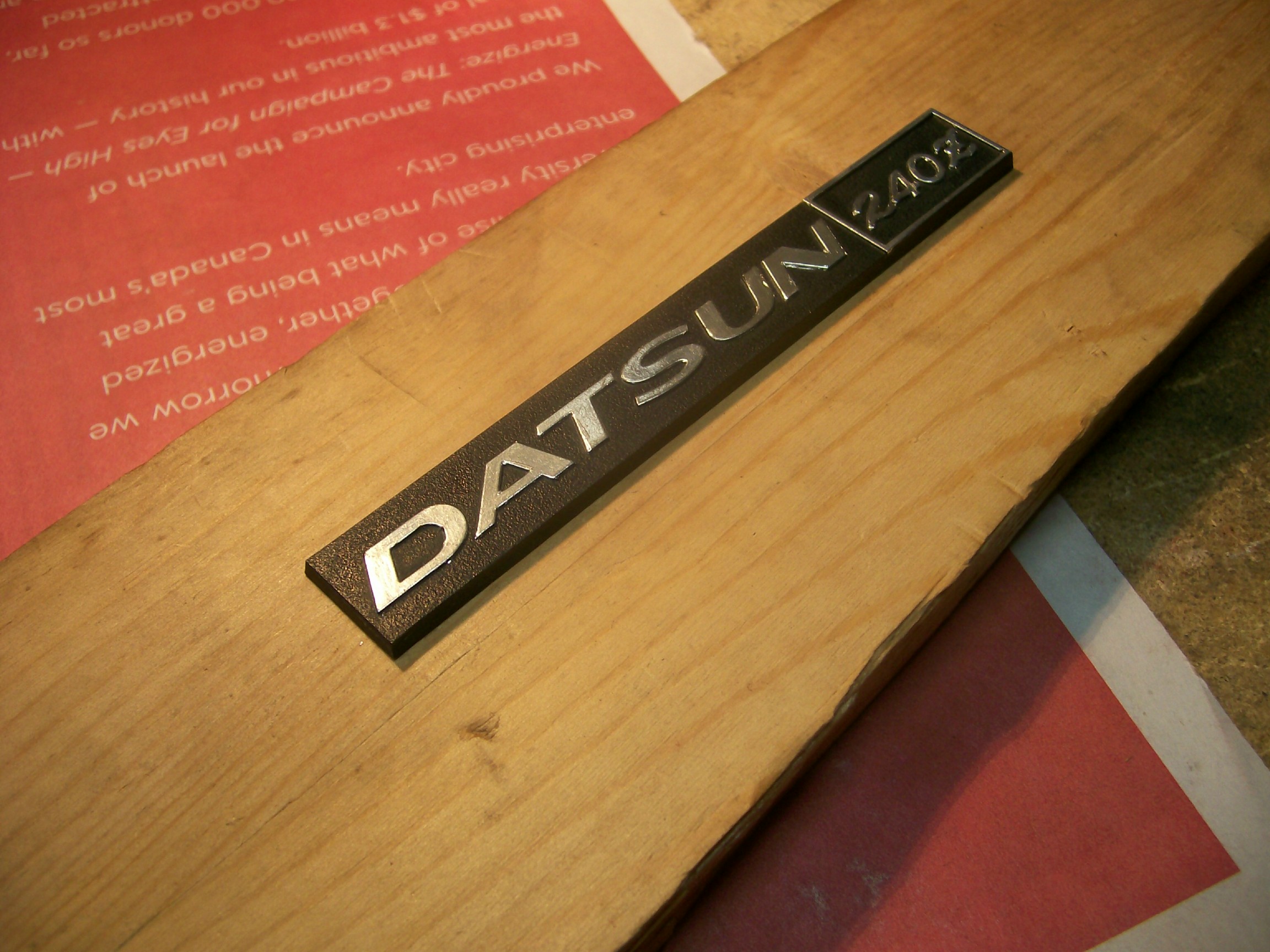
The topic of refurbishing the chrome lettering on the Z's dash features came up again today. I'd read several past posts by members, including those the recommended the use of the silver Sharpie pen. I tried this on the 'Datsun 240Z' logo plate for my glovebox door. While the results looked ok, it proved not to be very durable. As a matter of fact, the ink came off on the kleenex tissue that I'd wrapped the piece with for protection during storage. Maybe some clear acrylic would have helped. Just the same, I now had to start over. This time, I decided to try something different. I'd read about the chrome foil that scale modelers use for simulating chrome trim on plastic kits. Pictures of their results looked really promising, so I decided to give it a try. A page-sized sheet of adhesive-backed foil cost about $10 at the local hobby shop, so I figured I didn't have much to lose. The results were better than I'd ever cared to hope for. Here are some pix of the work I've completed so far -- two pieces: the glovebox logo and the centre console insert plate. The foil itself has about the same feel as the foil wrap used in a package of cigarettes. It's very thin and you need to be very careful peeling it off the backing sheet. Also, the adhesive on the back is very, well, adhesive, so you need to plan ahead as to what your next move will be after you've peeled your piece off the backing sheet. One wrong move and it'll be stuck to something you hadn't planned on sticking it to. It does not un-peel easily, so you'll probably have to toss that piece and cut out a new one. You'll need a sharp hobby knife to make this work. As the instructions that come with the foil mention, 'sharp' means 'really sharp'. Use only a brand-new blade. In fact, the foil manufacturer recommends that you hone the brand-new blade to make it even sharper. I didn't do this and I didn't find it necessary. However, you're going to be cutting through actual metal and that means that you may need to replace your blade with a new one from time to time during the job. The tip-off will be when the blade starts to tear the foil. Unfortunately, that will be too late (i.e. your job will be ruined), so the moral is, don't cheap out on blades. This job takes a very steady hand and a lot of patience. It's also really important that you set up your work piece so that it well anchored, movable, and placed so that your arm and hand will be well supported and at the right height for both comfort and position relative to the work piece. Let's start with the console insert plate. This has mounting bosses and brackets that extend off the bottom, so I found a piece of scrap wood and drilled holes in the appropriate places so that the plate would sit flat on the board. I also made sure that the plate wouldn't jiggle or move around on the board (really important). The console insert plate has a number of full-perimeter chrome accent stripes. As you can see, the chrome was completely MIA on my plate... Although it would have been less risky to do each 'box' as four separate chrome strips, I didn't want to have cut-lines at the corners. Too easy to catch on and lift and edge when driving, and also not a clean appearance. So, after taking a deep breath, I cut a big sheet of foil and dropped it in place... The picture shows the foil in place and I've already 'burnished' it along the raised accent ribs. I found this best accomplished with a piece of high-acrylic cloth from an old shirt. Whatever you use, make sure it's smooth, soft and thin. Be really careful when you do your burnishing. It's all to easy to catch a bit of raised foil by accident and create a rip (and that means you start all over again). Do not burnish in the areas that won't be chromed (it's going to be enough of a chore lifting the excess foil away, without having it stuck to the work piece). You want to burnish only on the 'flats' of the raised ribs but not along the sides of the raised ribs. In the picture above, I've also started to do some initial trimming. Again, you need to be careful at every step along the way. Little rips turn into tears, and a tear can suddenly grows by a half-inch and ruin your work. (BTW, one of the photos shows an actual 'burnishing tool' that I had left over in my tool kit from the days of 'letraset' - it proved to be poorly suited for use with the thin modeler's foil I put it away immediately). The knife work requires practice to develop the right 'touch'. You need to find the right weight, the right 'steering' angle, and the right tracking edge (it's not a freehand cut). You'll learn how to find a ledge that you can run the point along. Once you get the knack of it, you can run a 4" straight cut in one move. In point of fact, you really need to strive for making these cuts in one move, because it's difficult to resume a cut without creating a little ragged edge. Also, the foil doesn't lend itself to 'clean-up' work afterwards. You really need to try to get it right the first time. The photo above gives a little closer look at the burnishing and the start-off cuts. Below, you can see me about to use my tweezers to pull the excess foil away after the first of my detail cuts... Here's the 'After' shot, with the excess foil completely removed... Below, you'll see the same process carried out for the first of the longer cuts... And, finally, the first rectangle completed (at this point I am feeling both happy and relieved)... It perhaps goes without saying that the raised strips around the outer perimeter of the plate were the most challenging to get right. Nevertheless, I was 'in the zone' by this time and managed to get everything done without any major incidents (just a couple of small ones ). Here's a photo of the end result: and... (The second photo won't load full-size for some reason) I was pretty happy with the results, given that this was the first time I'd ever tried using this foil. I was particularly relieved to find that I could cut dead-straight edges just by finding the right little ledge to let the knife tip run in (it's easier to feel these ledges than it is to see them, but they're there). Once you find the ledge, the challenge is to keep the knife tip moving steadily forward in the right direction. It's pretty easy to have the knife tip wander out of the ledge if you have the blade's 'steering angle' a few degrees off. When that happens, you've got trouble. Now for the glove box emblem. Different challenges here, given the many curves and inside corners. Same technique though. First, the backing board... Then mount the work-piece and cut a piece of foil... Lay the foil in place and burnish with your cloth... Look for the 'ledge' around each character and start to make your cuts. Curved edges are the most challenging, obviously. You may have to re-do many of the characters before you get everything to the point where your happy with your results. If you need to do a fix-up (like I'm doing with the '2' in the shot below), make sure you cut you new piece of foil to exactly the right overall size, so that it doesn't accidentally touch the foil on one of the adjoining characters... which will mean you'll now need to re-do both characters). Of all the characters in this logo, the 'Z' was the hardest to do. Save it for the last. Here's the final result (not the greatest of pix as I found it hard to get the lighting angle right)... All told, I think it took me about 3 or 4 hours to complete these two pieces. I found it useful to walk away from time to time, as it's pretty demanding of concentration and coordination. Nevertheless, it's real (metal) shiny chrome and it won't fade. I'm pretty confident about the adhesive, but I guess there's going to be a test of that sometime in the future when the car gets parked in hot sun for a few hours. The durability looks like it will be just fine, provided I never accidentally catch an edge while cleaning.


-
I think you've done a nice job with this. It'll look great when it's back in the car and, trust me, no one is going to ask you to pull the unit out so that they can inspect the quality of the plating job. I had the same issue with refurbishing the chrome details on my radio's faceplate. Although I haven't gone back to this particular piece, I did manage to generate some nice results for my car's dash logo (glovebox door) and console insert piece using scale modeler's chrome foil applique. I'll post some pictures in a separate thread.
-
Now if I could only find a complete car in the same shape! But priced differently. If nothing else, the pictures certainly offer an nice reference for the correct shade of 'Z Gray'. I wonder if others here still feel that the gray used on these wheel covers is the same gray that was used by the factory for the front grill and the rear trim panels?
-
.Are you saying that the zinc anode plate will/should retain a shiny appearance under ideal current conditions?
-
I like this approach. Who was your source for the mass-loaded vinyl sheet? How did the price per sq.ft. compare with the usual products like Dynamat?
I like this approach. Who was your source for the mass-loaded vinyl sheet? How did the price per sq.ft. compare with the usual products like Dynamat?
Good tip concerning the use of floor tiles as turn plates. For a light car like a Z, I wonder if it might not be a bad idea to load up the driver's seat with 150 - 200 lb of ballast (sand bags?) before doing a toe adjustment. Re compensating for front-to-rear differences in track/tread when doing a string alignment: The 240Z's wheelbase is 2305mm, while the front and rear track measurements are 1355mm and 1345mm respectively, That would call for a 5mm step-out adjustment of the jack/axle stands at the rear. This doesn't seem worth fussing over. The error created by a 5mm lateral difference when played out over a 2305mm lengthwise distance amounts to only 0.005mm (i.e. two ten-thousandths of an inch). I found a nice pictorial explanation of how to do a string alignment here: http://www.hotrod.com/how-to/chassis-suspension/ctrp-1204-determining-wheel-alignment-string-your-car/
Try JDM Car Parts. They list the bag at $75.00. Not sure if it's NOS or a reproduction. http://jdm-car-parts.com/collections/body-exterior-parts-nissan-fairlady-z-240z-260z-280z-280zx?page=4
Plain old white vinegar. Ignore the extra-strength 'cleaning' version. I have no idea what they do to make it extra-strength, but it undoubtedly will involve a different pH level. No sense in adding a new unknown to a process that's already challenging .
I'm afraid I'm going to have to go metric on you here: 100 grams of epsom salts for every 1 litre of vinegar. In your terms, that would be 3.53 oz (by weight) of epsom salts for every 1.06 US gallons of vinegar. Ignore anything you read about adding sugar, saccharine or corn syrup to the bath to act as a brightener. There are a number of reports that this achieves very little in the way of brightening and can end up creating a sticky mess. I bought some very handy graduated mixing tubs (clear plastic) from the hardware store. They hold 2 litres of liquid (0.53 US gallons). Using these, I discovered that my '2 kg' (by weight) container of epsom salts measured out at 1700 millilitres (by volume). I am using 16 litres of vinegar (4.2 US gallons), so I needed 1600 gm (by weight) of salt. Using my weight-to-volume conversion factor of 1700/2000, that meant I needed to measure out 1360 mL of salt (46 US fl.oz.) to add to the bath. Using fluid volume measures, the mixing ratio is therefore: 1360 mL of salt for 16000 mL of vinegar or, 1 fl.oz. salt to 11.76 fl.oz vinegar (i.e. 1 measure salt for every 11.76 measures vinegar) You'll probably be using 4 US gallons of vinegar (4 x 128 = 512 US fl.oz.). That means you'll need to add 43.5 fl.oz. of salt. (512 divided by 11.76). If you get the same volume-to-weight conversion that I did, the 43.5 fl.oz. volume of salt would weigh 51.2 ounces, or 3.2 lb. Be sure to check my math before doing your purchasing and mixing. I'm now using just a single, 4"-wide hoop of 'Moss Boss' zinc foil in my 5-gallon pail. The inside wall of the pail has a slight draft angle, so I lap-soldered the zinc strip to create a hoop of just the right diameter to lodge about half-way down in the bath. The pail measures about 10.5" in diameter at that point, so that means I have about 130 sq.in. of exposed zinc inside the bath (i.e. just shy of 1 sq.ft.). I soldered 12" lengths of solid copper wire at the '9' and '3' positions on the hoop and use these as my connector terminals for the 'POS' lead of the power supply. They also give me a hand hold that I can use to pull the zinc hoop out of the bath between plating sessions.
I've thoroughly hijacked Ramsesosirus' thread. Sorry about that. Thanks, Mike, for the pix of your #303-painted Z (nice car, BTW). I think I see more blue under-tint here than I do for the #240 paint (the #240 seems to have more of a yellow under-tinting). Looking at the avatar picture of my Z, it looks like at might very well be #303 that was used. I guess I'll have to get a pint mixed up at the paint shop and do a test shot to see whether I'm right.
What is the part that you're trying to plate? Can you possibly add more surface area to your zinc anode? Pieces of zinc can be joined together by mechanical means, with a jumper wire for electrical connection, or - preferably - by a solder joint. Zinc takes solder very well, BTW. After reading the Caswell forum narrative, I'm inclined to agree that your power supply may be toast. Nevertheless, perhaps you could try exercising it with a more typical small-resistance load, just to see how it performs. I've used a double-filament #1157 bulb (front park-t/s or rear taillight) to good effect before I got access to a controllable-volt/amp power supply. They're surprisingly robust. Just solder 12" insulated wires onto the shell and end contacts, add some alligator clips and you're good to go. The cold resistances are 0.7 and 2.5 ohms (altho maybe higher with the filament heated up). I got my plating project fired up again late yesterday afternoon. I'm using a vinegar-and-epsom-salts bath rather than the Caswell electrolyte. I tried one 'big' part (ignition coil mounting clamp) and one 'small' part (brake line hold-down clip). Surprisingly (to me), the big part was easier to do and plated very nicely (it's about 20 sq.in. and I used about 3A, IIRC). The small part has proved to be a lot more challenging. I had to re-do it three times before I got a decent result. And I still need to do it a fourth time to try to get it right. I've confirmed that 0.3A is about right for this application. The L-shape of this part makes it challenging to get both legs plated and on both sides. On Attempt #1, the zinc wasn't really depositing. I had wire-wheeled the part prior to the acid bath and I now believe that my wire wheel causes problems (it's brass, mounted on my bench grinder). Maybe it's a burnishing effect, maybe the brass loads onto the part's surface, or maybe my wheel is contaminated with other stuff, I don't know. I do know that I'm not going to wire-wheel anymore parts before plating. Before Attempt #2, I took the part pack to clean metal by re-blasting (I'm using ground glass media). That helped a lot and now, back in the bath, I had plating happening. Unfortunately, I got greedy and cranked up the current to see what would happen. The zinc started to turn black. For Attempt #3, a re-blasted once again. Current now back to the correct 0.3A. After ~ 5 minutes I had a fairly good result -- except around the ends. The part was suspended in the bath using a copper wire hooked through the holes at either end of the clip. Apparently, the electrical field set up in the part doesn't 'flow' into the small areas at the ends of the clip (i.e. the parts of the clip that are 'outboard' of the holes). There's a very distinct 'half-halo' boundary around the hole where the plating visibly stops. For my next -- and, I hope, final -- attempt with this part, I'm going to solder the copper wire to the very tips of the part (on the back side, of course) so that the electrical path comes in the from the very ends of the piece. I'll let you know how it turns out.
Can anyone post some pix of the #303 Green Metallic?
I have the same issue with my Z. It was re-sprayed over its original 907 'Racing Green' (not my favourite colour, BTW) with a darker green metallic. Like yours, my paint has a visible, fine metallic content and shows a bluish tint under certain light conditions. The colour used on our cars might be either the '303 Green Metallic' that was offered for 1974-75, or the '240 Green Metallic' replaced it in 1976. There appear to have been four different paints used on the Z that carried the name, 'Green Metallic'... 113 - 1972-73 - Green Metallic - aka 'Avocado' 302 - 1974-?? - Leaf Green Metallic 303 - 1974-75 - Green Metallic 240 - 1976-?? - Green Metallic I can see my/your paint being described as 'Dark Green Metallic' so as to distinguish it from #113 and #302 (which are definitely not dark), and maybe also to distinguish #240 from #303. Maybe someone who has a car with the original 303 or 240 paint can comment.
Just read Steve's reply, which is clear and right to the point. Good to know. Note that he's recommending 140mA per sq.in. I hadn't seen the Caswell calculator before. It confirms that "sq.in." refers to the total area of the wetted surface of the part(s). When I referred to the possibility that "sq.in." might have to do with 'line of sight' effects, I wasn't really referring to the case of a hollow pipe or tube. Instead, I meant that 'sq.in.' might be referring to the 2-dimensional 'face' that a part presents to the zinc as it streams off the anode. I now know this theory was wrong. I played around with the Caswell calculator for a while. Everything is pretty straightforward, except for the case of the bolt. Here, the calculator proved to be a little more sophisticated than it looks. It appears to take the area of the threads into consideration (rather than just considering the bolt shank as a long smooth cylinder). It also appears to calculate on the basis of a hex-shaped bolt head (rather than just a square head, as the diagram would have you believe). Looking at your own plating tank set-up, you might want to consider replacing your little zinc sheet with a full-perimeter ring. This helps to offset masking/shadowing and makes it less likely that you'll need to turn the part(s) during plating to get full coverage. Even with the 'ring' anode, though, I've found that the surfaces of the part the point 'up' and 'down' (rather than 'sideways') often don't plate properly and I need to re-jig the way the part dangles off its hook. I've been using a product called 'Moss Boss' for my anode. It's intended use is to control of moss growth on wood-shingle roofs (applied as a flashing strip along the roof peak). It comes in a roll that's about 40' in length and 4" wide. Inexpensive, but you might have to special-order it. Let us know how you make out. I'll be re-starting my own plating project tomorrow. I, too, experienced problems on my last attempt and was so frustrated that I just put everything away. Since then, I think I've discovered what I was doing wrong and have also gained access to a controllable voltage/current power supply courtesy of Grannyknot. I'm hoping for much better results this time around.
So far, the question of, "What does 'sq.in.' mean?" remains unanswered. I recall that Steve/nix240 weighed in on this in another thread a few months ago, so it might be worth looking that up. His results looked first-rate, but I remember him offering the usual caution that, 'Settings depend on your particular set-up, so you'll need to experiment.' FWIW, here's a link to a very nice electroplating write-up by a talented amateur restorer in California. He included it as part of a multi-segment documentation of his work on an early-year E-Type Jag. Guaranteed to consume an entire evening of your spare time... http://www.mckennasgarage.com/xke/jag_16.htm
hmmm. With all those ripped-apart old cars in the background, that set-up looks a lot like a backwoods still... Just missing the condensing coils. According to my notes, the typical guide for setting the current is 140mA per sq.in. of part. One person showing successful results said that he used only 100mA per sq.in., while others have gone as high as 250mA per sq.in. A lower setting is safe but really stretches out the plating time. A higher setting speeds things up, but going too high will result in a thick, fluffy, black-ish zinc deposit on the part. You probably know all that, though. You mention that your test part is a "5 inch piece of copper". Is that a 5" length of wire, a 5" length of tube, or a 5" piece of plate? The reason I ask is this: It's never been clear to me how "sq.in." should be determined. In the many DIY plating articles I've read, No one has ever explained or justified their rationale. Here's the issue: Let's say that the part to be plated is a 5" length of 1/2"-diameter thin-wall tube. Ignoring the two end surfaces, the total outside surface area on which the zinc could deposit would be 3.1416 x 0.5 x 5 = 7.8 sq.in. Taking the inside wall surface into account, the surface area approx. doubles to be come 15.6 sq.in. However, electroplating is a 'line of sight' process, so maybe "sq.in." means the profile area of the part (i.e. what the zinc anode 'sees' from one side). In this case, it's 5 x 0.5 = 2.5 sq.in. But then, if you have two anodes (i.e. one on either side of the part), the profile area would double and become 5.0 sq.in. And if you have a full-perimeter anode lining the inside of your plating tank (as I do in my set-up), then I have no idea what the profile are of the part would be. So: Depending on what "sq.in." means, you get four (or five!) different answers, ranging from 2.5 sq.in. to 15.6 sq.in., and the preferred current would be anywhere from 0.35A to 2.2A. And then there's the issue of creating the correct pH level for the electrolyte (and what it should be, and how much it really matters). And whether the electrolyte 'wears out' (I've never been quite sure how that would happen). And whether the electrolyte needs to be heated (some say it's important, some say it makes no difference). All of these issues could affect the correct value of amps per sq.in. of part. Put together, they could be the reason why people will tell you that achieving good results, 'depends on your set-up'. One thing for certain, though: Make sure you don't have the polarities reversed for your power connections to the anode and the part. And don't ask me how I learned that this is an easy mistake to make. I, for one, would be grateful for someone shedding some light on the 'sq.in' mystery. Maybe the Caswell manual explains this?
That's been my experience, too. I have both the Engine and Dash harnesses out of my 70 Z as I work (slowly) through my refresh project. I bought a couple of special terminal removal tools from Vintage Electric last year for about $10 and I've been using them with great success to pull both the male and female terminals from the plastic connector shells so that I can do a proper job of removing the tarnish ('oxidation' doesn't really cover it). Nothing else I tried (including dental picks and an assortment of small screwdrivers) would do the job. However, the VC terminal extractors only work for the white-shell, multi-pin connectors. They're of no use for the two big single-conductor, blade connectors in the Dash harness (heavy-gauge White and White-Red primary wires, IIRC). The brass terminals and the plastic covers for those connections were nicely toasted and the wire strands were oxidized for about 1/4". Bad grounds are always a worry, too. Excepting that in the headlamp pigtails (replaced), my harness wiring (copper and sheathing) seems to be in pretty good shape.


Important Information
By using this site, you agree to our Privacy Policy and Guidelines. We have placed cookies on your device to help make this website better. You can adjust your cookie settings, otherwise we'll assume you're okay to continue.