Namerow
Free Member
-
Joined
-
Last visited
Everything posted by Namerow
-
 hmmm... You mention buying new felt washers (a good idea) in the same sentence where you talk about cleaning the bronze bushings (also a good idea). However, the bushings with the felt washers are not the ones that bind up. Instead, it's the bushings inside the cast-aluminum mounting blocks that locate immediately underneath the base of each wiper arm. These are the bushings that really count when it comes to freeing up the overall system.
 -
A few cautions: The circlip that secures the centre linkage on the motor shaft might be a bit tired. Replace it if you're in doubt. The centre linkage is supposed to be covered by a dustboot. In most cases, the OE dustboot has disintegrated and will probably by MIA. Steve (nix240) offers a nice replacement piece. Your chances of finding an OE Nissan dustboot are slim to nil. As has been pointed out by many others, the primary culprit for slow Z wipers can be found in the bushings provided for the left and right-side wiper arm drive spindles. The original grease coagulates into something that has zero lubricating properties and, instead, creates a lot of binding between the bushing and spindle shaft. Clean everything out and repack with a modern, synthetic grease. Some say that this simple step makes the need for the Honda wiper motor upgrade unnecessary. It's possible to put the crank arm back on the motor output shaft so that it's 180 degrees off. You can't tell which way is right unless you mark the arm and the end of the motor shaft before you disassemble. If you get it wrong when you reassemble, the wiper blades will sweep down rather than up, ruining the paint on your cowl panel. To protect yourself from this calamity, don't install the wiper arms until you're sure you've reassembled things correctly. To check without risk, just put a clothes peg or even just a piece of masking tape on the end of one of the wiper blade spindles to simulate the wiper arm. Then watch which way things move when you turn the wipers on.
-
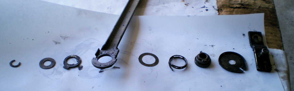
The photo below will show you the correct assembly order and up/down orientation for the linkage parts (sorry, but I don't have the name of the original poster so can't provide credit). To assemble, just start stacking the parts on the crank arm spindle, working from right to left. FWIW, I did a lot of experimenting with this assembly last year to see if I could discover the purpose of the spring and the eccentric bushing. My conclusion is that the eccentric bush is there provide some compliance in the linkage (so that the long connector arms don't bow or get over-pulled), while the spring is supposed function an anti-slop device (which it might if the tang wasn't broken off -- which it almost always is). I concluded that the spring has nothing to do with the 'auto-rise' function (which was just Nissan's way of saying the the wiper motor parks the blades a bit higher than their lowest wiping-mode sweep point).

-
Looks very promising. The question now is whether the softening effect is long-lasting vs. temporary. Hope you can give us a few updates over the coming weeks. Even if the effect turns out to be temporary, it may prove to be valuable during the installation of components where some 'give' is needed (such as the fuel filler neck that you've shown in your video). I find it curious that none of the commercially-available 'rubber and vinyl softener' products come anywhere close to delivering this kind of result.
-
This UK article might provide some additional insights into product differences and techniques for surface preparation... http://www.realclassic.co.uk/techfiles/tank_cleaning_and_sealing.html You might even consider corresponding with the author, as he will offer the benefit of multiple experiences rather than just sample-sizes-of-one.
-
Unfortunately, 'two-pack' catalyzed paints fall into the same 'user beware' category. You really need a forced-air mask (and a full paint suit) to be safe. This website from the British government's Health an Safety bureau is worth a read for anyone planning a D-I-Y paint job at home... http://www.hse.gov.uk/mvr/bodyshop/isocyanates.htm In particular, check out the, 'Common body shop myths' section.
-
Interesting clip. Too bad there's not another one available that illustrates the flow around the back of the car, where the other half of the Z's issues reside (front-end lift being the issue at the front). I spent almost 15 years of my engineering career with a Canadian company that was one of the four world leaders in wind tunnel design in the day (the others were Sverdrup in the USA, TLT in Europe, and Meidensha in Japan). For reference, my company (DSMA International -- now reborn as Aiolos Engineering) designed and built the Porsche wind tunnel in Weissach back in the late 1980's and later designed the Williams Grand Prix Engineering wind tunnel in the early 1990's. We also worked for Volvo, SAAB, Honda, Ford USA and Europe, GM, Chrysler, Hyundai, BL Cars, as well as for clients in the aerospace and fuel/lubricants sectors. Those were interesting days. The picture of the old Nissan wind tunnel shows a rather old-fashioned design (even for its time) with an open circuit layout (affects efficiency), a small test room cross-section (affects accuracy), and the absence of an in-floor measurement 'balance' (floor/ground effect ignored, yaw measurements complicated or ignored). In terms of absolute accuracy for Cd measurements, it probably couldn't do much better than +/- 3 to 4 %. By contrast, a modern tunnel delivers +/- 1% or less. Nissan replaced this tunnel with a much larger and more capable, closed-return circuit design sometime in the late 1970's or early 1980's (it was in place and operational when I visited circa 1988). Production car aero development was in its infancy at the time when the Z was being designed. The oil embargoes in the early 1970's were what really made the industry get serious (Americans will remember the 55-mph national speed limit as another component of the 'energy crisis' days, while Nissan captured the spirit of the times with its marketing slogan, 'Datsun Saves'). There was major industry investment made in the acquisition of modern, high-accuracy/capability wind tunnels throughout the 1980's, as well as for accommodating the cost of aero test/development hours into new-model development budgets. It's all become pretty formulaic now, but that's because of all the ground-breaking work that was done in those new wind tunnels throughout the 1990's. I remember that one of the important issues that designers were trying to sort out was how to optimally locate and size the extractor vents to enable effective cabin air flow-through. As all of us Z owners know, this was something that Nissan hadn't really got a handle on when the Z was being developed!
-
Does your 12/70 240Z have the same mix of detent-type hinge on the driver's door and interleaf-type hinge on the passenger door?
-
Autonomous vehicles are probably inevitable, but the idea of turning these things loose on public roads at such an early stage of development is wrong-headed. It all sounds like such a cool idea -- until somebody gets hurt or killed. I'm equally troubled by the idea of drones as personal transportation devices. What could possibly go wrong with that idea?
-
Dupli-Colour is a well-known brand, so that's a plus. The (one) customer review on the merchant's site is positive, and that's encouraging too. The problem, of course, is that the colour probably won't match the seats (which are major components of the interior and aren't a good candidates for vinyl paint). If the match is close, though, this could be a really convenient solution. Those doorskins from RoadsterWerx look great and the price seems reasonable (or, at least, it's in balance with other interior restoration products being offered for the Z). Having spent dozens of hours restoring the skins on my car, I can tell you that 'patina' is highly overrated. If these skins had been available when I re-did mine, I would have bought them instead of doing the resto.
-
So that's it. You're using beer as your electrolyte!
-
I used a Canada-based paint supply specialist (Parasol - Toronto, Ontario... www.parasolinc.com ) to custom-mix a butterscotch 'dye' for my interior panels. Great product, great results. Goes in your HVLP paint gun with the consistency of water, but sets up as a stretchy vinyl 'skin'. The magic of synthetic chemistry. I needed about 2 qt to do all of the hard plastic and soft vinyl trim pieces (I did not do the door cards, seats, or roof liner). The custom-match product cost about Cdn $115/qt, so ~ C$230 total. I used SEM products for the prep work ('Soap', 'Plastic & Leather Prep', 'Sand-Free', and 'Plastic Adhesion Promoter') and those probably contributed another C$70 to the job, so call it C$300 total. Parasol sells their own line of surface prep chemicals. Note that I started with black panels, so it required about 5 light-to-medium coats of the dye to get the job done. I think you could do a color 'refresh' job with just 3 coats, possibly only 2. The hard plastic panels were easy. The diamond-textured soft vinyl pieces, however, require a lot of pre-paint preparation work to get rid of all the ArmorAll (silicone) that's typically been rubbed into these surfaces over the years. The silicone hides down in the bottom of the grooves used to create the diamond pattern and will cause the dye to 'fish eye' if you don't get it fully removed. Count on doing at least 5 applications of 'SEM Soap' (must be scrubbed in with a kitchen-grade 'scotchbrite' pad) and two or three applications of 'P&L Prep' before you spray on the dye. The dye doesn't have a solvent smell, but the airborne fumes created during application will make your head swim. After it sets up, the dye's adhesion is very good and its surface toughness/scratch resistance is probably on par with the OE surfaces (i.e. modest). I would have no hesitation applying this product on a door card -- although I will point out that the OE door cards are actually a subtle two-tone, and that would require a second color-matched dye and masking to re-create properly. Parasol's dye product is packaged in standard metal paint cans. You could probably get it delivered by surface shipment, but I'm not sure about air. Sydney is a pretty big place and has lots of industry, so I'm pretty sure that you could find a domestic paint specialist like Parasol somewhere in your city (or in Melbourne or Brisbane). Like Parasol, they`ll probably also offer a range of surface preparation products to use before the dye application.
-
This would seem like a challenging stamping for anyone to re-create. I don't think I've ever seen steel reproductions being offered (e.g. Tabco). Does anyone know whether metal repops have ever appeared on the market?
-
Over the years that I've been following this sitier, I've been collecting info by 'cut-and-paste' into Word docs and building my own reference library that's organized by categories and topics that make sense to me. As this particular thread began to build, I discovered that some of the territory that we've covered here had already been addressed some time earlier. Here are a couple of early contributions made by a couple of well-known voices on this site: From Zed Head: "The washers are supposed to bottom out on that inner metal sleeve. It leaves the bar kind of hanging in between, with the web of rubber of the bar bushing supporting the weight. The scalloped layer of rubber on the washers is more of a final damper for any movement. That's my take on the design. I think that the idea is to minimize pathways for the high frequency vibration (specifically, diff howl). But the rubber gets weak over time. If you've compared a new rubber transmission or diff mount to an old one, you can actually see the difference in rubber stiffness. I've had good luck with the urethane mounts, with 2-3 washers added to the inner sleeve to leave a small air gap between the urethane and the washers. Basically, extending the sleeve length. The same general concept of the Nissan design. A little bit of float. My diff noise is less than when I got the car and had old worn clunky stock mounts. I had pretty bad clunk and howl. I also added an RT-style front mount now. I think that most of the urethane mustache bar bushings are designed to clamp the bar tightly, race-car mentality. Therefore, they transmit a lot of noise and vibration to the body. Another opinion." and from ZKars: " The mustache bar bushing rubber is likely old and soft or beginning to break down. Tightening down the nut just locks the bushing's center steel tube and the steel face of the washers to the frame. You rely on the hardness of the "eye" bushing rubber and the hardness of those "nubs" on the upper and lower washer to prevent the rotation/twisting of the M-bar that might allow it to touch those up-rights or anything else. Squishy bushings will let it twist all over the place. I'd love to have a Go-Pro and a light back there and take the car for a good spirited drive to see just how much that M-bar twists around."
-
2nd second.
-
Kudos to Kats for being able to finally produce for us a well-organized set of clear photos and graphics, c/w parts numbers. I still have a few questions, though. The M-bar mounting/isolation scheme for the Early S30's with the angled halfshafts (SoP to until 71-06) appears to use a unique isolator design, in which the rubber core extends out around the lower end of the metal outer shell so as to provide a soft lip for the plain-metal-washer lower 'stopper' to sit on. This apparently didn't work very well (the rubber lip probably sheared off over time). Does any one have a photo of this early-version isolator (PN 55476-E4100 or 55476-E4101). In the section view of the early-version isolator, the clearance gap marked as 'A' is intriguing. In the FSM, it's called 'B' and comes with the following explanation: "Replace differential mounting rear insulator if the dimension 'B' is less than 5mm." I believe that the lower 'stopper' (washer) is supposed to sit on the hard stop created by the square step machined into the bottom of the tapered mounting stud. Then the securing nut gets torqued to 60 lb-ft. The lower stopper doesn't even touch the insolator. So that means that the 'A' (or 'B') gap is intentional and the hanging weight of the Diff would be entirely taken up in shear by the rubber core of the insolator. This would be quite different in principle from the later style arrangement with the rubber-faced lower stopper. In that later design, the hanging weight of the Diff would be taken through the rubber stopper and into the tapered mounting stud. Makes me wonder why they even retained the rubber core for the isolator in the later design. Comments, anyone? As Kats photos demonstrate so nicely, there were at least three different M-bar mounting/isolation schemes used over the life of the 240-260-280 models. The early #1 version (angled-halfshaft 240) and the final #3 version (280Z) are easy to position in the Z's chronology and well-documented in Kats' photos. The 'middle' #2 version, however, is puzzling (it's the one that uses the thick/concave rubber-faced stoppers with no ribbing, top and bottom). Depending on how you read the parts numbers, this version may (or may not) have applied to the entire run of later 240's and the 260 and we should be seeing photo evidence of this style of stopper frequently. But that doesn't seem to be the case. Most of the suspension/drivetrain photos I've seen over the years show the deep-ribbed stoppers that were used on the 280Z. Comments? More specifically, does anyone know the production dates over which this 'middle' version (thick/concave rubber-faced stoppers with no ribbing) was used... 71-05 to 73-07? (i.e. later 240Z only) 73-08 to 74-11? (i.e. 260Z only) 71-05 to 74-11? (i.e. later 240Z and 260Z) To add to my confusion, the FSM for the 260Z continues to show the early-style insulator design (ref. Figure RA-13).
-
And now that you've seen 'The Might Duke' in action, have a look at this video promoting what I'm going to guess is state-of-the-art for contemporary, high-end collision repair systems. Pretty cool stuff, featuring a, 'Infiniti' 3D laser measurement/alignment system working in conjunction with x-y-z adjustable support pedestals. The rack is sold under the 'Car Bench' brand name. The pull-arm system is sold under the 'Piranha' brand name.
-
This promo video from a collision-repair equipment manufacturer just happens to feature a 280ZX for the initial demo sequence. The ZX has structural damage to the left-front and panel damage to the left rear. The video offers an interesting perspective on how our cars' structures respond to this kind of straightening operation. Everything you see here was probably done on a hurry-up basis and strictly by eye, so as to focus on demonstrating how the equipment works rather than the niceties of procedural details. Or, at least, I hope that's the case!
-
IIRC, there's a CZCC thread from about two years ago in which the poster illustrated a tank repair where he split the tank along the join seam. An option worth considering? Another option, of course, is to just find a replacement tank that's in better shape.
-
Nissan seem to have had lots of complaints about rear-end noise for the early cars. The text in the Mar-71 TSB bears this out to some extent, although it implies that the problem showed up only in cars with the automatic transmission. The (expensive) change in the entire diff mounting scheme that occurred in 71-06 is a better indication that the issue was significant (at least, as far as customers were concerned) and affected both the manual and automatic-equipped cars. According to the online 'Car Parts Manual' reference, the factory made a change to these 'castellated' rubber washers as of 71-04 (roughly the same time that it changed the diff mount design so as to straighten out the halfshafts). There's anecdotal evidence to suggest that the change amounted to making the 'fingers' longer. That would make them more compliant (which would help cut down on the transmission of gear whine noise into the rear cabin area). If somebody has a picture showing a set of NOS early washers in their factory packaging (PN 55474-21000 or 55475-21000), we'll know for sure. Unless you're dead-set on originality, it may be better to go with the long-finger versions (the ones shown mounted on the studs in your picture), working on the theory that 'original' isn't always 'best'. Also: Given that there are two different PN's for these castellated washers (irrespective of vehicle manufacture date), can someone comment on whether this means that there's an 'upper' and 'lower' washer? If there is, what's the difference and how do you tell which one is which?
-
-
There clearly is a correct process. And one that produces consistent, high-quality results. If there wasn't, there wouldn't be a plating industry. Our problem is the none of us knows with certainty what that process is, and how whether it scales successfully from industrial-size batches to little, hobby-sized batches. I've recently been associated with a university-based research project being conducted with a big commercial plating operation located in southwestern Ontario. Next time I'm visiting that campus, I'll see if I can break out some time to have a chat with the prof who's leading the research team. It would be interesting to hear what he has to say about do's and don't's for these hobby-scale plating set-ups. My fear is that he'll start showing me chemistry equations, in which case I'm doomed.
-
'wavy' 'rippled' 'serrated'
-
No worries. I didn't have any knowledge on the subject until I saw this thread and became curious. The Sugarman article is an interesting read, for anyone interested in learning how extreme-pressure lubes work differently from garden-variety greases. And now I know why gear lube stinks so bad (sulfur).
-
hmmm... I tried just hooking my shop vac up to the cabinet so as to help reduce media 'air pollution' my workshop. It didn't seem to work very well, so I dropped the idea and switched to setting the cabinet up on a workmate in the back yard. It never occurred to me that that the vacuum hookup might also serve to reduce clouding inside the cabinet, so thanks for the tip. I think I'll continue to only use the cabinet outdoors, though. I've done enough damage to my lungs over the years without adding silica dust to the mix.