darom
Free Member
-
Joined
-
Last visited
Everything posted by darom
-
 Adrian, I think my thermotime switch is faulty - I will need to run some tests on it per the FSM. I grounded the thermotime pin while cranking the engine. The amount of fuel it sprays should be enough. I was actually afraid to flood it. Nothing has changed, I was testing the wrong leads back to the cabin for 12V (user error). There is voltage at the coil and there is continuity between the coil (-) and the ECU's pin 1. I will run some tests on AFM per the Fuel Inj. book. Can a bad TPS cause the engine _not_ to start? I removed the intake while changing the studs/gasket - maybe the TPS sensor finally decided to quit? I will re-check its connector settings as well. Thanks for your help!!!
 -
Another update: - Ignition switch's START wire to 86a/76 (ign. relay) -> continuity - Ign. relay 4/47/86 to ECU's 4 pin -> continuity - CSV pin 47 to the ign. relay 4/47/86 pin -> continuity - CSV pin 47 shows 12V when the key is in START (it is alive!) - When the thermotime switch's 46 pin is grounded -> CSV squirts fuel (I took it out) Installed the CSV back into the intake, the engine just cranks. I can't hear the injectors clicking at all. Fuel pump runs. I am guessing the ECU doesn't pulse the injectors on pins 33, 32, 31, 30, 15 and 14. I wish I had a circuit board diagram to see which part of the ECU is managing the injectors. My replacement ECU is going to be here in a few days. Thanks!
-
Excellent, thanks - I will trace the wire (my 2 fuel inj. relays are out, should be a pretty straight forward operation).
-
Update: no voltage is registered on the CSV connector, neither in the case when 46 is grounded, no voltage shows up on the other CSV plug. The ECU is definitely fried.
-
Adrian, I will run those 2 tests (voltage at CSV and pin 46 ground) tonight after work. Thanks!
-
The lead path from pin 4 goes to the T300 transistor (C1833 L281) on the 'daughter' card circuit. Does anybody have a circuit board diagram for a 1976 ECU? Thanks!
-
Adrian, you are _good_! I ran the test on page 69 (CSV disconnected) and it registers my battery voltage on pin 4. So I think the wiring is good through the ign. relay all way down to the ECU. I think the ECU fails to provide ground on pin 21 for the CSV (page 71). Hmm, I just rechecked - my ECU doesn't have any leads on pins 20, 21. Now I am guessing the Nissan engineers ran the wire (21) from CSV to the ECU harness plug just for testing sakes. The CSV gets its ground from the thermotime switch, positive off the fuel ign. relay (47). On my circuit board the following pins are soldered: 1-18, 30-35, 26-27. You can be right, that pin 4 might be the culprit in my ECU. I checked the resistor on pin 4 and it looks ok (24k ohm). Red-yellow-orange-gold 24k Ohm +/- 5%. Beyond that I am not much help testing the board :-( For pictures, please find them here: http://s24.photobucket.com/albums/c1/darom/280z/ Thanks. I appreciate your guys help!
-
Adrian, thanks for a good explanation. I am basically at the same conclusion as you are in regards to the PO's wiring. The CSV never got the ECU's 12V to engage, thus the butchered wiring solution (The CSV on 280-z works only when the engine is being cranked. That's why the PO's wiring was off the START ignition wire to the CSV directly bypassing the ECU pins.). When I bought the car, the PO re-assured me that he had replaced the ECU with a rebuild unit. That's why I have been delaying its replacement (esp. when the car's engine ran) until I discovered the relay/CSV hook-up etc. The cold start system circuit passed the test (page 71 of the Elect. Fuel Injection 280-z book" with the harness disconnected from the ECU, starter solenoid lead wire disconnected, ign. key in START position. Here is the reference: http://www.atlanticz.ca/zclub/techtips/efisystem/280zfuelinjectionbook.pdf I found a used 76 ECU - I will update the thread once it is installed. Maybe someone will benefit from this in the future. Adrian, I like your avatar signature: "Registered Ign/ECU Nurse: :-)
-
Update: did a manual (touch 3 times the ignition lead wire) ECU injector test per the Injection Book and it failed. It appears the ECU fails to start the injectors. The wiring harness passed all the tests (continuity to injectors, to coil (-) and to grounds). I took apart the ECU, all soldered connectors were in a good shape, tested each lead. I guess I will start looking for a ECU replacement (the one I have is from a different year). What still puzzles me how the heck the car ran before I removed that CSV hot wire/relay and redid the manifold/intake gasket?
-
I had too much coffee -- the ECU controls the injector pulses. I completely confused the transistor unit (spark control) with the ECU (injector pulses). There is continuity on pin 1, ballast resistor's (-)/tach lead. I am going to take apart the ECU and see if pin 1 inside is not loose (I will re-solder it). Someone on zcars.com forums had some issues with old solder points creating bad connections.
-
Another update: - I have 12.2V at the coil (+) terminal when the ignition switch is in 'ON' position (good news). I guess no need to run a direct (+) battery wire to the coil's one. - When the engine is cranking, I see 9.6V at the + coil post. - The transistor's BW post shows 12.1V when the key is in 'ON'. When cranking, it shows 9.6V. - If I remove the coil's wire to the distributor, I am getting a nice size spark. I traced both green/red wires from the engine coil area (2 wires which also go to the distributor) back to the transistor's red/green posts. There is continuity on both. Still no injectors' clicking noise at all. I am wondering if the transistor is failing, time to convert it to the GM HEI module? The engine doesn't even 'cough' for the 1st time I try to start it. Thanks!
-
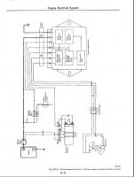
Thanks, FastWoman, for catching my typo. I fixed it - it is Cold Start Valve (CSV). I checked with the voltemeter, on the ECU bulk connector, that I have battery voltage on the pin number 1. The problem is that I don't see the battery voltage on the coil side at all when the ignition key is in the ON position. I am going to run a positive cable from the battery directly to the positive side on the coil and see if the engine starts. If it does, then I need to figure out why my ignition switch is not providing 12V to the coil. Wouldn't it be the ignition relay (pass. side, kick panel)? Thanks for the tip. Would you mind please checking this out? - I have the complete 1976 wiring diagram (76circuit.pdf). If I trace Pin 1 from ECU, it goes to: White Cable -> Blue -> C4 Block -> Black with Blue (BL) -> Ignition Switch BL I don't see how pin 1 connects to the - (negative) on the coil? Doesn't the negative come to the ballast resistor (and coil) from the ignition transistor unit which sends pulses (see attached picture)? Here is the diagram (sorry about the size, it is 10MB): http://www.filefactory.com/file/b05b301/n/76circuit.pdf I apologize about the crappy 20 sec wait time for a free account. Thank you, Den
-
Update: - replaced the coil with another used one (engine cranks, but no start) - installed another ECU (same result) - retested per the Inj. Manual the ECU bulk connector pins (everything tests ok) - tried advancing/retarding the distributor (no difference). When the engine is being cranked, I cannot hear the injectors' clicking noise. A pulse should be coming from the ECU. 2 bad ECUs? I am going to test the distributor's 2 wires tomorrow and the elec. ign. fuel relay. A few questions: If I pull the coil wire on the distributor side, and try to start the engine, I should see a spark if it is close to the ground, right? If the ignition switch is in ON position, should I be able to see voltage below 12V on the coil's + and - posts? Do these get energized only when the ign. is in START? Thanks!
-
Hello, I need your guys' input on something the PO did to my car. 1976 280z, stock, with 79 alternator (no voltage regulator). I appreciate your time reading this. I replaced all the injector connectors + 4 more (air valve, cold start valve, thermotime and temp switch). In addition, I took the intake/exhaust manifolds off to install the studs. The PO used a lot of wood screws to hold them. A new Nissan gasket was installed. Everything looked nice and clean. I was happy. While replacing/soldering the connectors, I noticed the PO ran an ignition wire (START position) to the engine bay's Bosch aftermarket relay (one of the relay's contacts was connected to positive on the battery, and the relay switched wire to the Air Cold Valve's one of the connectors.) The other wire on the ACV was attached to the thermotime's switch connector (basically, like stock's setup to loop both switches together). He left the stock ACV connector loose. In my infinite wisdom, I figured WTF he needed this part for, and removed his wiring mod to roll back to the stock setup. After that I checked per the Fuel Inj. bible book, all my ECU pins for Ohms and voltages. Everything checked out ok including the AFM pins and fuel pump operation. Now here is the problem: the car cranks, fuel pump works, but it won't start. The engine almost starts in the first 10 seconds, coughs a few times, and then nothing happens. I can keep on cranking the starter, but it doesn't start the engine. At this point, I got mad at myself for being adventurous, and replaced the whole INJ/ECU harness with a spare 1976 one. I thought maybe I messed up the polarity of the injectors which could be causing this. Or the PO hacked it at some time. Well, even with the original wiring harness, the engine wouldn't start. I'd hate putting that mod back, because I don't understand why the PO provided the positive signal to the Cold Start Valve when it can be simply disconnected (one of the steps the Inj bible mentioned was to unplug it completely)? Did the PO do it to provide the positive to the coil this way? Now, (putting the flame suit on) since the car's ignition is messed up already, I am ready to install the GM HEI module with my stock 76 distributor to bypass the in-cabin ignition transistor to get better spark/response and drop that ugly ballast. Should I do it and then waste another couple weeks tracing the problem :-) ? When I took the intake off, I didn't touch the distributor, each spark plug cable was labeled. Any ideas why the PO ran that relay modification to get the positive wire to the Cold Start Valve? Thanks in advance! Den
-
-
<i>Is that stock sound proofing material hard to remove?</i> I used a chisel and a putty knife on my 76 to remove the factory insulation. Some of it came off easy. I didn't have to dry ice any pieces or use a heat gun. I did feel my right hand got twice as strong after this procedure :-)
-
-
I had similar simptoms on my 76. After removing the master brake cylinder and the brake booster, I found half a quart of brake fluid in the booster. The master cylinder leaked, damaging internal booster seals. I had to apply the brake pedal to the floor before they got enganged. The calipers in the front had brand new pads, the disc rotors were evenly worn (the PO replaced them before I bought the car). I would have never guessed what caused it. There were no visible leaks. So in my case it was a combination of the leaking master cylinder and a damaged booster. I am at the stage of replacing some brake lines, front calipers, rear cylinders and drums. Good luck with your project.
-
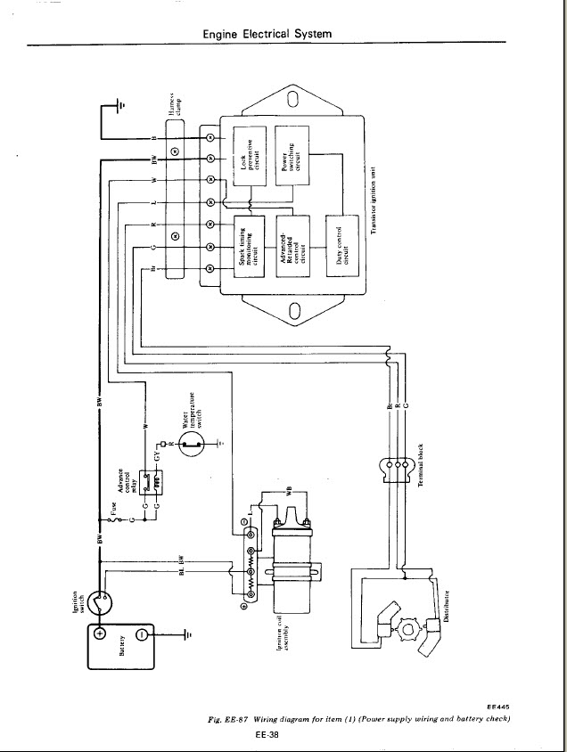
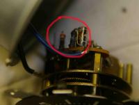
Can anyone help me finding the right specs for the clock's resistors? It looks like on mine they both got burnt out. The only resistor colors I can see are: red-yellow-black-?-?-? There is a capacitor next to the burnt 2 resistors. Maybe you know this capacitor's specs as well? Thanks in advance!
-
Great, thanks! I will start looking for a 75 harness.
-
Is the 1977 engine/EFI harness swappable into a 76 model? Are all connectors the same and have the same strands of wires? Is color coding the same? If not, can 75 harnesses be moved to a 76? Thanks!
-
Update: after fixing the burnt 2 red/green wires laying on top of the a/c compressor, my oil pressure gauge doesn't peg out any more (good news). The bad news the gauges still don't work, haha. Can I run a direct wire from the oil pressure sending unit and connect it directly to the yellow with black stripe lead on the back of the oil gauge itself? And do the same for the water temp wire? These sending wires are not fused anywhere, right? Thanks!
-
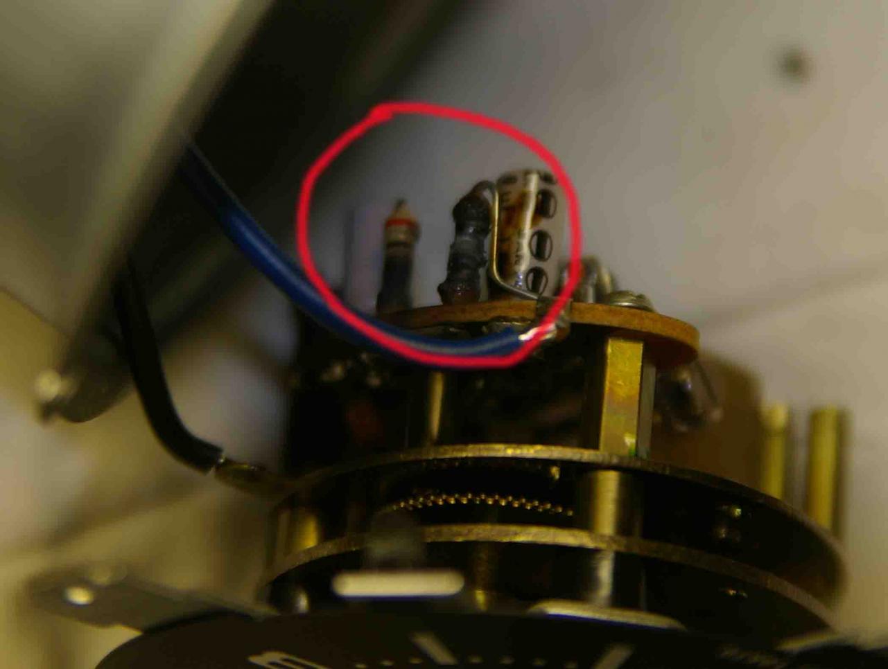
Here is another weird thing: Engine is off. When I trace (voltmeter set on Ohm) the oil pressure gauge sender's wire (Yellow with black stripe) from the gauge itself to the passenger side junction block (C-5 green), it shows ok. However, if I unplug the pass. side wiring engine harness (page BE-3, diagram BE594A) plug and try to check continuity with it in the engine bay, I am getting all 6 wires showing continuity with the Yellow/w Black wire inside the cabin! That's the plug in Picture 1. WTH? Thanks, Den
-
69firebird, thanks for checking it - that would explain why my windshield wiper doesn't work. Can you please tell me if you have a pair of wires going to your distributor (red/green)? Is your car a later model or points? Also, would you please check the continuity from the thermal sender (water neck) to the chassis ground (engine off)? Mine shows that it is grounded. And the last one - from the oil sender post to the chassis? I appreciate your help! Den
-
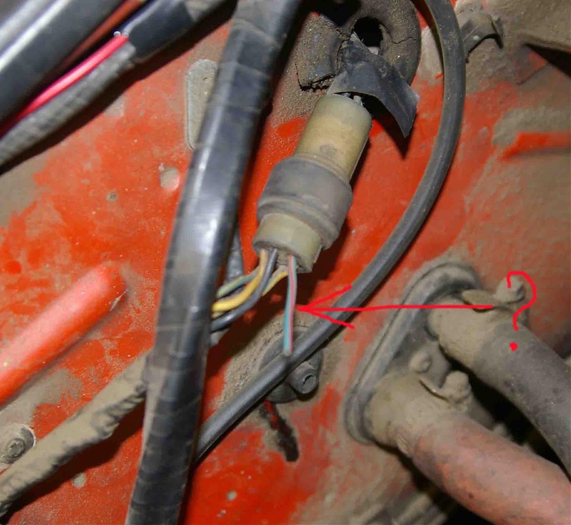
Hi guys, I went through the wiring diagram a few times and need your input. a. 1976 280z - I studied the wiring diagram for 1976 and it looks like a lot of wires' colors are wrong coded. I am trying to determine what the cut wire is in Picture1. I am assuming this 6 wire plug is for the whole engine harness? On my car's diagram I can't find the Green with Red stripe wire (BE-94). b. My water temp/oil pressure/voltage gauges don't work. The water temp gauge goes to maximum indicator position. The FSM suggests ignition relay, voltage regulator and bridging the thermal transmitter's yellow wire to see if the gauge's needle fluctuates. I checked the continuity off the thermal transmitter's contact (yellow wire) and it is grounded. Is it supposed to be grounded? (BE-34 diagram shows ignition relay that grounds it via black wire). Logically it shouldn't. Hence bringing the yellow wire per FSM is pointless. c. I found a pair of Green and Red wires (2 pairs) at the junction block next to the externally mounted distributor coil. One pair used to lay on top of the a/c compressor and is completely melted. The other pair goes into the wiring loom headed back to the car's cabin. I guess since the car is without the points distributor, I don't need this pair of Green, Red wires? Can I cut this pair off the distributor? Picture2. d. How often do voltage regulators go bad? Your help is appreciated. Thanks, Den