Nissanman
Free Member
-
Joined
-
Last visited
Everything posted by Nissanman
-
 I would describe that tray as having a cosmetic blemish:classic: I wish some of my rust "problems" were as good as yours:tapemouth
 -
I have added a couple of CAD images and expanded the captions to the pics. on my Imagestation site for the body rotisserie. I figured that was the easiest way to inform those who are interested in the plans. Let me know if there is anything else you need to know. http://www.imagestation.com/album/pictures.html?id=4287967191
-
The '73 Z in the background is already on the prototype, the second rotor was sold. I have all the plans and dimensions for anyone who wants them.
-
Don't want to hijack but I have a series of pics. showing how I made a rotor for a fellow Z enthusiast: - http://www.imagestation.com/album/pictures.html?id=4287967191 If that link is a problem just use the link in my signature. Look forthe album: - Car body rotisserie construction
-
You mean to say that LEADED petrol/gas is still sold in the U.S.:eek::eek: We haven't had that stuff for years!
-
The only current the ammeter doesn't display is that drawn by the starter. Or at least, that is how it should be wired:ermm: Choose your poison, ammeter/voltmeter, either is better than the alternator/charge lamp. Don't be shy when it comes to fuseable links/maxi fuses etc. They are a lot easier and cheaper to replace than wiring looms. My '65 Fairlady has no protection whatsoever from the alternator o/p to the dash loom and ammeter. The plan is to fit a maxi fuse [tucked under the alternator out of sight] to protect the whole deal. Yes, the F/L goes at the starter, please replace it as a matter of urgency. [Doesn't have to be an F/L, you can get maxi fuses now which are huge in current capacity.] It will also protect the wiring if the battery is accidently connected frack to bunt:tapemouth
-
The ammeter is there to indicate what is happening to the battery. If the meter reads in the negative, the battery is discharging into a load. If it reads in the positive, the battery is being charged by the alternator. Any direct connection from the battery to the alternator output, effectively shorts out the ammeter. Therefore, the above two conditions are no longer indicated. Normal operation with engine running etc. is a float voltage of ~13.8V, causing the ammeter to read just to the + side of zero. To see the ammeter "dancing" is an indication of a wildly varying load and is demonstrating how effective the regulator and alternator are in compensating for that load. As long as the battery gets a charge, all is well:classic:
-
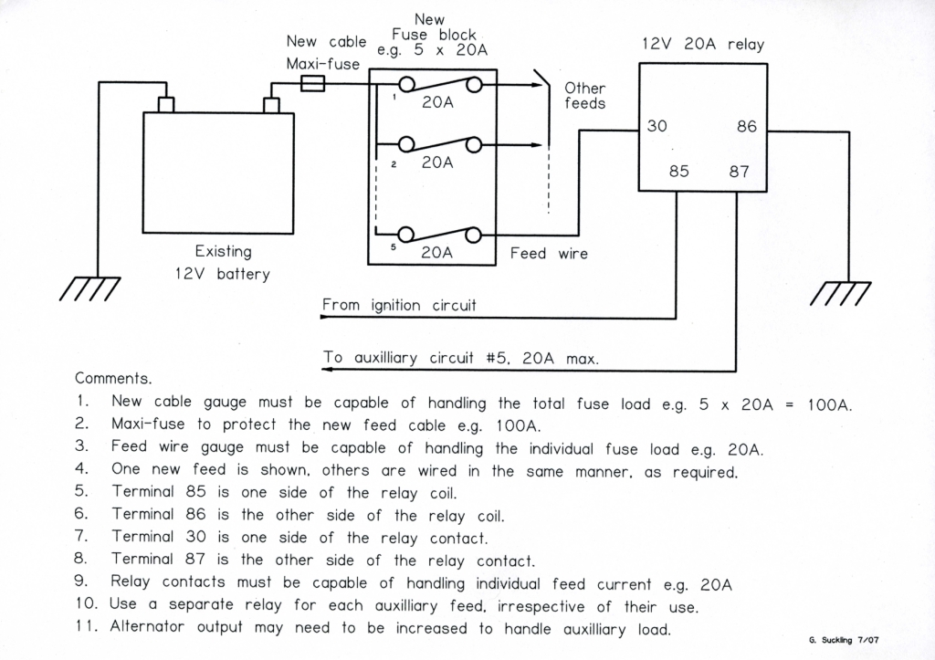
I've said it again and I'll say it before: - Make sure you run any additional electrical load via correctly rated fuses, relays and correctly dimensioned wiring. Having a pseudo nuclear power station as an alternator is fine but don't expect existing [factory] wiring to enjoy the new load you want to give it. "Protection is very important", said the Bishop to the ActressROFL
-
What you describe is an impending failure. The regulator is losing the plot. If not repaired, this condition may lead to overcharging of the battery, resulting in loss of electrolyte and possible, remote but, explosion of the battery. Burning out of globes, overloaded fuses and general global warming are also possible:ermm: Get the electrics checked by a competant Auto Electric Shop if you are not confident in this area. The alternator output will ramp up when revs. increase but it is the duty of the regulator to, you know, regulate If you are not into originality, might be a good time to adopt an internally regulated alternator and dispose of the old click clack relay type regulator.
-
All's well that ends well:) Something like that tests yor patience AND your sanity:tapemouth
-
Might be best if you remove the diff. housing with the moustache bar still attached [assuming it is still in the car]. Once out of the car you can get a decent go at the retaining nuts. They screw on to studs which screw into the rear cover. If one of the nuts is stripped, just cut it down with a grinder until it falls away. The studs can be renewed, but if you are clever enough you shouldn't damage it with the grinder:nervous:. The Haynes manual calls them "differential rear mounting bolts" but they are really screw in studs with a nyloc nut.
-
If you accidently put the new battery in backwards, i.e. postive to earth, negative to car, that will rupture any fuseable link the alternator. From then on it is zip, zero, diddly squat until that link is repaired:tapemouth
-
If these are not suitable let me know and I'll email you the originals.


-
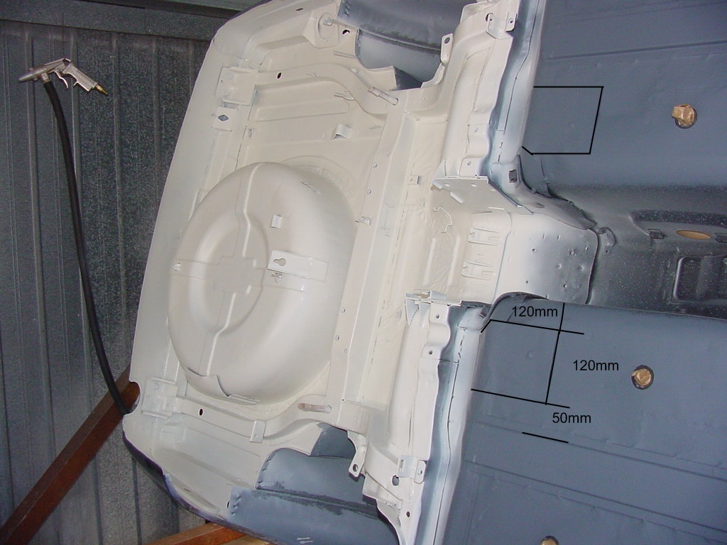
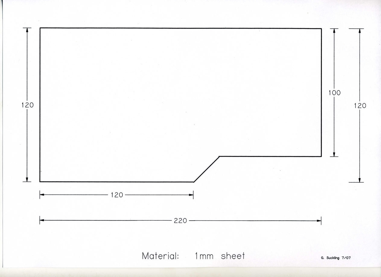
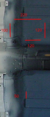
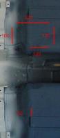
How sad is THIS:nervous::nervous: That car is STILL up on the rotisserie:tapemouth Anyhoo, rear panel is 220mm x 120mm tapered to 100mm at the rear as per pic. Located 50mm inboard of the edge of the floor rail. Front hole is 460mm from the edge of the T/C rod mount. Not critical in location, 10mm diam and only a drain hole.

-
Something a bit closer to you folks in the States: - http://www.painlessperformance.com/assets/07Catalog/page38.pdf
-
When you say "the same thing happens", I assume you mean the car starts, runs, but when left overnight the battery goes flat. There may be a load on the battery even when you turn off the key. That is easily determined, and avoided, by disconnecting the battery terminal after you shut the car off. Next time to start it, re-connect the terminal and see how the battery performs. Barring another stuffed battery, it should be alive and well. Once it starts, you need to check the charging function of the alternator. See: - http://www.classiczcars.com/forums/showthread.php?p=211105#post211105 If there is a load draining the battery overnight, you need to investigate as what and where. It might be as simple as a radio/tape player or rear de-mister left on. Fuse pulling is the quickest and simplest method to narrow it down. Then you might have to go to plug pulling etc. A car will run for quite a while on the battery alone and the alternator alone for that matter, until you try to restart it:tapemouth
-
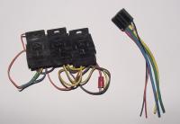
The relay bases on the left are Bosch slide together type and have part number #3 334 485 008 stamped on them. The base on the right is pre-wired and you can just see the diode mounted below the connectors.
-
Fuse blocks: - http://www.narva.com.au/Fuses_16.html Relays: - http://www.narva.com.au/Switches_18.html There are some relay bases which clip together to create a nice "bank" of relays. Try your local wrecking yard and see if you can find them. Also, use relays which have a protection diode [or resistor] connected across the coil. This prevents the back e.m.f. of the relay, when it releases, generating a voltage spike into the wiring . The diode makes the relay polarity conscious but the spike suppression is well worth the effort. If you have ever chased electrical gremlins in electric door locks and alarm systems, you'll know what I mean:finger: Any relay socket can be modified to insert this diode [resistor], which then means you don't have to use the relays with the protection built in. Depending on design, relays and fuse blocks should be OK in the engine room. Just avoid heat, oil and water splash. If you have the real estate available, inside the cabin would be ideal. My advice is DO NOT use Nissan relays. They seem to be a design all on their own. Stick to the more conventional types like Narva, Bosch, Hella etc. which use the 30, 85, 86, 87, 87A pinouts. The last thing you need is some weird arse wiring requirement which applies to one relay type only:ermm:
-
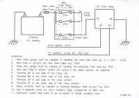
Revised power feed drawing.
-
A continuity check with an Ohm meter should ONLY be done on an unenergised circuit. To check power you should use a Voltmeter. Just trying to prevent a fried meter or confusing results:finger:
-
Well,you've let some smoke out and that is a no no:( Couple of possibilities: - a fried or broken a power wire, a fried or broken blower motor a fried or broken speed control resistor device If the blower works on full speed but not at reduced speed, the speed control resistor or switch could be kaput. You really need to do some voltage measuring on the relevant connectors to see when and if you lose the 12V supply. [The blower fuse a likely suspect, check it again with a Ohm meter for continuity, or a voltmeter for 12V]
-
If you suspect the fuel, why not check the level in the float bowls prior to cranking the engine? They should be full from the last time it ran. If they are empty then the fuel is draining away somewhere. That would introduce a time delay until the carbs. re-filled. [An electric pump would still need time to do what the mechanical pump is doing now, you just won't be cranking the engine] At the same time you could disconnect the fuel pump outlet hose and check that the pump spews out fuel when you crank it. Needless to say, TAKE CARE AND NO SMOKING From what you describe, it does appear to be a fuel issue.
-
Like he said. The bar runs to the lower pair of screws of the door catch. It is some distance from the outer door skin, ~25mm, so it's not as if it contacts anything apart from the mounts at the front and rear panels. The very top of the door has a double panel that may cause you grief. It extends down from the window slit by about 70mm but the lower edge is still ~10mm from the outer skin. It has some Nissan chewing gum here and there to bond the lower edge to the outer skin. Guess where my door is dented:cry:
-
The seal can be removed without removing the timing/front cover. Fiddly, but achievable. If you do anything on the timing chain etc. then the front cover does have to come off. 4 x 6mm bolts clamp the sump to the front cover. Not something that I have done on an engine still in the car:eek: The crank seal is usually pressed in till the front edge is flush with the cover, it doesn't bottom out on anything as such. There is a weeny ledge about 20mm in, but if you press the seal in that far I'm guessing it will have gone in too far. The depth of the cover at the hole is only about 8mm and the seal is about the same width. You may not need to adjust the seal depth, just inspect the crank pulley suface with this in the back of your mind:nervous: Pic. shows front cover seal area and sump bolts x 4. I just happened to have an L24 front cover next to my 'puter!!
-
No.1 Water pump. Easy enough to do, just be careful getting all the fasteners out. If they are corroded, it may be wise to renew them with a stainless bolt kit from a vendor. No. 2 Front main seal. The design of the crank is such that the main seal runs on the O.D. of the crank pulley. That means that once you remove the crank pulley, there is ample room around the inside circumference of the seal to hook it out with the appropriate tool. Re-insertion of a new one could be achieved without removing the radiaiator. If you are doing the water pump, may as well pull the rad. and give yourself better access. Note the condition of the surface of the crank pulley where the seal rubs. If it is badly grooved, the new seal will have an issue from day one. Either have a speedi-sleeve fitted to the pulley OR re-insert the new seal to a different depth that the old one was. Then the lip on the new seal will have a fresh surface to seal against. Strongly suggest you use a shop manual to get some baground info. before you start:nervous: Pic. shows seal and crank diameters.