pparaska
Free Member
-
Joined
-
Last visited
Everything posted by pparaska
-

-
-
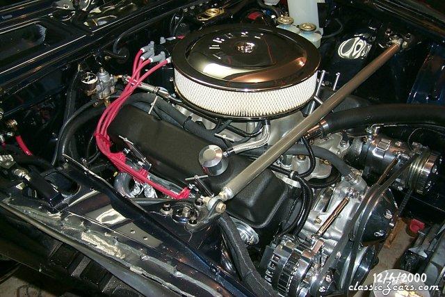
 Ron - That is beautiful!
 -
 Looks great!
 -
 Beautiful job!
 -
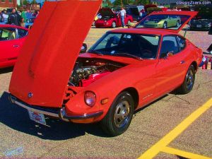
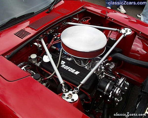
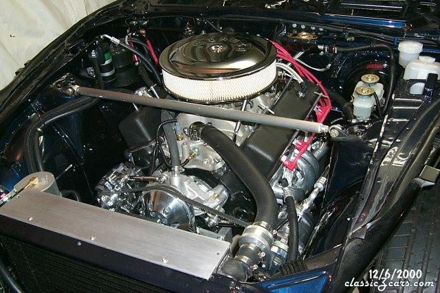
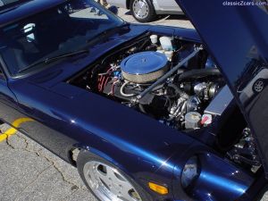 I can't vote on my own car . But I wanted to thank you KAMKA-Z, for a great photo of my fender and underhood. If you have any more please email them to me at pparaska@comcast.net Did I meet you any time during the Convention?
 -
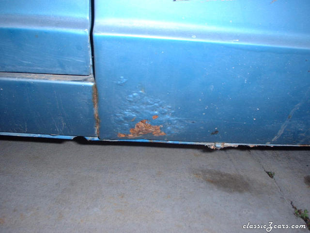 Yep, typical. The deal is that behind that fender in that area is the front of the outer rocker box section. Alot of loads go through that area, and it usually is rusted if the fender is. Wet debris gets between the fender and rocker in that area and then it's fed a supply of rain and wash water from the cowl drain.
 -
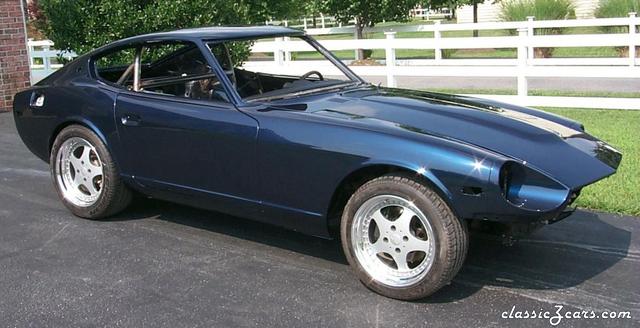
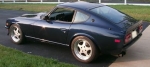
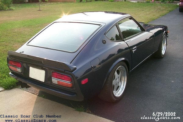
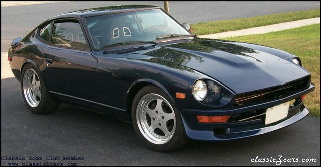 The color used is from the 95 to 97 Audi A4, Color name: Europe Blue Mica. Color Code: LZ5T (Audi used the same paint color name for the later (98 and newer), but it's a lighter blue, but not as nice looking IMO. The paint code for that color is also close to the earlier, nicer color, LZ5K, not LZ5T as used on my car.)
 -
 Thanks for the Comps! Worth? That's a tough one. I have WAY too much money in it, especially the body and paint! Right now it's insured for over $23K agreed value with Hagerty, but that's a good bit less than I have in it! Not interested in selling it. I worked on it for too many years to give it up now!
 -
Dan, I was thinking of the effect of a longer arm to the vertical load on the bearing farthest from the center of the contact patch. The closest bearing. Vertical forces are all that matters, but a moment equalibrium and vertical force equilibrium eqs. are needed to solve them. Preaching to your choir, I know. Anyway, if the center of the contact patch is a distance D laterally from the inboard bearing, and the outboard bearing is a lateral distance d from the inboard bearing, the relationship for the vertical forces on the bearings are: F(outer) = Center of Force * D/d (downward) F(inner) = Center of Force * (D/d - 1) (upward) The only thing that matters here is the center of the contact patch (assuming all weight acts there). If you add a spacer to a given wheel/tire combo, then D gets larger. As you can see both loads go up. But if you add a spacer to a same width tire wheel that has more positive offset (hub face close to pretty side of wheel), so that the center of force is still acting the same lateral distance from the bearings, all the forces on the bearings, spindle, etc. are the same. Rick, I used that catch all phrase "all else being equal", saving myself from having to discuss the loads due to wider tires :devious: That phrase always gets you out of trouble, huh? Thanks for that explaination though! Yes, wider tires do add to the loads - in several ways.
-
I'm not being testy - sorry if I offended. I was just defending my assertion that it's the center of the contact patch, not the wheel mounting surface position that matters. Experiences are fine, but if all the info isn't there (as in where the contact patch center was on the cars that had spacers and bad bearings), then it's not worth anything as far as added information. The devil is in the details.
-
I'm sorry, but that statement is just completely false. The center of the tire patch is all that matters. The wheel mount surface does not, as long as a spacer is used to move the center of the contact patch back to the stock location. Well, if we can't agree that physics is the only thing that matters here, then I don't think we can have a useful discussion. Physics is the only thing that DOES matter, as far as what loads, etc. are. A wheel spacer used to bring the total offset of the spacer and wheel to the stock location DOES NOT CHANGE THE LOADS ON THE BEARINGS/HUB/SPINDLE. Now if you put larger stickier wheels/tires on, you'll be adding more loads to the parts, no matter if you have spacers or not. The mounting surface of the wheel has nothing to do with the loads the bearings and spindle see, if a spacer is used to bring the center of the contact patch to the stock location. If you don't care about physics, then I'm not sure what yard stick you are using. The laws of physics DEFINE what happens in the phsical world. Have the racers you've seen with spacers put on wheels/tires that have moved the center of the contact patch away from the stock location? I bet that's the reason their bearings are going. Porsches have been using wheel spacers for decades without any problem. Of course, the factory engineered the setup, not some amatuer racers, so the PHYSICS are correct, and there aren't problems. Pete Paraska - Mechanical Engineer, MSME
-
-
-
Z2ManyZs wrote: I disagree. If the center of the contact patch remains in the same place, the bearing and hub loads remain the same, all else being equal. The issue here is that that many of the wheels available on the market have more positive offset than what's required on the Z. The spacer just allows you to move the offset of the wheel to a place where it fits correctly on a Z (in other words, reduce the offset of the wheel). If 20mm of positive offset (mounting surface 20mm towards the pretty side of the wheel from the 0 offset position) is what's needed on a Z (this is what I think is correct) and the wheel you want to use has 58mm of offset, then you'd need a 38mm (or about 1.5") spacer to come up with a combined wheel/spacer offset of 20mm positive. Think of the spacer as an extension of the wheel mounting surface toward the center of the car. Again, this would place the center of the contact patch in the same place as stock, and the hub and bearing loads would be the same as stock. True, but there are about 30 years of experience of racers and enthusiasts that have not shown this to be a problem with the Z. Except maybe it has contributed to some stub axle failures. I'll let the racers (John Coffey, Keith Thomas, etc.) chime in on that one. Not if you keep the total offset of the package the same (center of contact patch in the same area), the tire outside diameter the same. Shear loads go up linearly as you move the contact patch center point away from stock. Moments go up by the square of the change (roughly). I disagree. If the spacer needed is nearing 3/4 inch, I suggest going to a bolt on adapter spacer. This way the lug studs don't get over worked. Bolting an adapter to the hub is NOT a problem in any way, as long is it's a good design and material. The only drawback is that those expensive adapters are now only good for that offset wheel you've chosen and if you go to another wheel with another offset, things won't work for you. If the wheel had more offset, you could add a think spacer though. Good point, but if the total offset of the wheel/spacer is the same as stock, there is no change in where the centerline force acts, and therefore no more stress on the hub/bearings/spindle, etc. As with any change in wheels on a car, you must keep the center of the contact patch at or near stock or things like loads on these parts and suspension and steering geometry ARE effected, and usually in a "bad" direction.
-
Thanks Dan! The steering wheel is a very important choice, as it represents the part of the car most important in control and your sensitive hands are on it all the time. Therefore, a choice here is important and one I've left until last! I'll be buying the Leather 120, either in black or grey, along with the snap-off system. Money well spent! Thanks again for sharing this product and companay with us!
-
Thanks Enrique! I bought the light assemblies used from someone in Canada. No telling what the deal is. I doubt I'll be selling them . I wonder what the true functions of the individual bulbs is SUPPOSED to be. Logic tells me that the bulb in the yellow lense should be the only one that flashes with turn/hazard functions. I think I see what you mean about needing another wire to run back there. The turnsignal switch on the 240Z (US anyway) handles shuttling the stop and turn signal current to the individual bulbs, and only one wire is used to serve the high brightness filaments in this setup. Hmm, I hadn't considered that. I can see I will need to run two more wires now. But I'll run them from my custom turn signal relays (I have the plans for the US version of using relays to take the current load off of the turnsignal switch on my website). Thanks,
-
I have a set of used European 240Z tail lights (not the 5 bulb Japanese taillights). The way they work now is that both to top outer bulb in the red lens and the bottom bulb in the yellow lens flash with the turn signals and hazards. This doesn't seem right to me, as I thought only the bulb in the yellow should flash with the turn signal/hazard. Maybe someone just used the wrong bulb socket harness on these lights before I got them? Anyone know for sure how they are supposed to work?
-
I'd think that they are all the same, within a given set of years. I've tested 240Z and 280Z fuel gages and they seem to respond very similarly to the same sending unit. I measured the extent that several 240Z sending units had for full motion of the float, while out of the tank and they all were very close to 88 ohms Empty, and 8 ohms Full. No telling what the true Full reading will be until I've filled the tank (car not on the road). I'm waiting until I get it on the road, fill the tank, and make a resistance reading on the sender before I finalize what resistors to use to calibrate my Ford type gas level gage. The senders do vary a bit due to manufacturing tolerances, but I doubt that they'd actually match gages to senders, as there seem to be no markings even on a brand new sender to differentiate a high ohmage one from a low one.
-
And for just that reason, the sender is the part the usually goes bad! The friction between the finger and the windings on the sender is what can cause bad readings. I've seen this on several of the units. The gage has only friction at the pivot points, and the movement is imparted only through magnetic field fluctuations. A few years ago, the sender was still available new from Nissan, not sure about now. If anyone is interested in how to calibrate a gage of this type, check out the "gage calibration" link on my home page.
-
Thanks, Mike! There's a slim chance that the car will be driveable in time to make a cross-country trip to the MSA show this year. If it makes it and you make it, you'd see it then/there!
-
-
-
-