hotsho111
Free Member
-
Joined
-
Last visited
Everything posted by hotsho111
-
Picked up this set https://www.amazon.com/dp/B0BS95X63W?psc=1&ref=ppx_yo2ov_dt_b_product_details so I had a few sizes and the 3mm side was right on the money (and actually 3mm from my calipers). Cleaned and tested everything else for proper contuinity, and using a little dialectric grease to hold the ball on the spring it went together pretty smoothly. Sorry about the slightly blurry picture. Soldered a few of the top connections and good to go!
-
Ya, getting a new switch would be easiest, but thankfully the way the board on mine is broken I think it could be repairable. It does hold together, the spring in there currently is just waaaaaay to strong. I'm going to try buying some new springs and see if a softer, shorter spring works a bit better. If that doesn't work I'll probably temporarily just hardwire low beams up and look at replacing it with a different switch or possibly 3d printing a different solution
-
Quick followup after putting everything back together: I'm not sure if the spring (on the circuit side) in there is too strong, but with everything assembled I can't get the switch to actually toggle. I took it apart again and even trying to carefully set the depth to see if I could get it to work properly it seems extremely fiddly. The best I could accomplish pushing the switch and getting it to the other side, but it wouldn't reset (so it effectively acted like a normal switch at that point) Is the tolerance on that normally super tight? I might try replacing the spring or might just look at replacing the whole thing with a push button switch
-
Awesome, thanks!
-
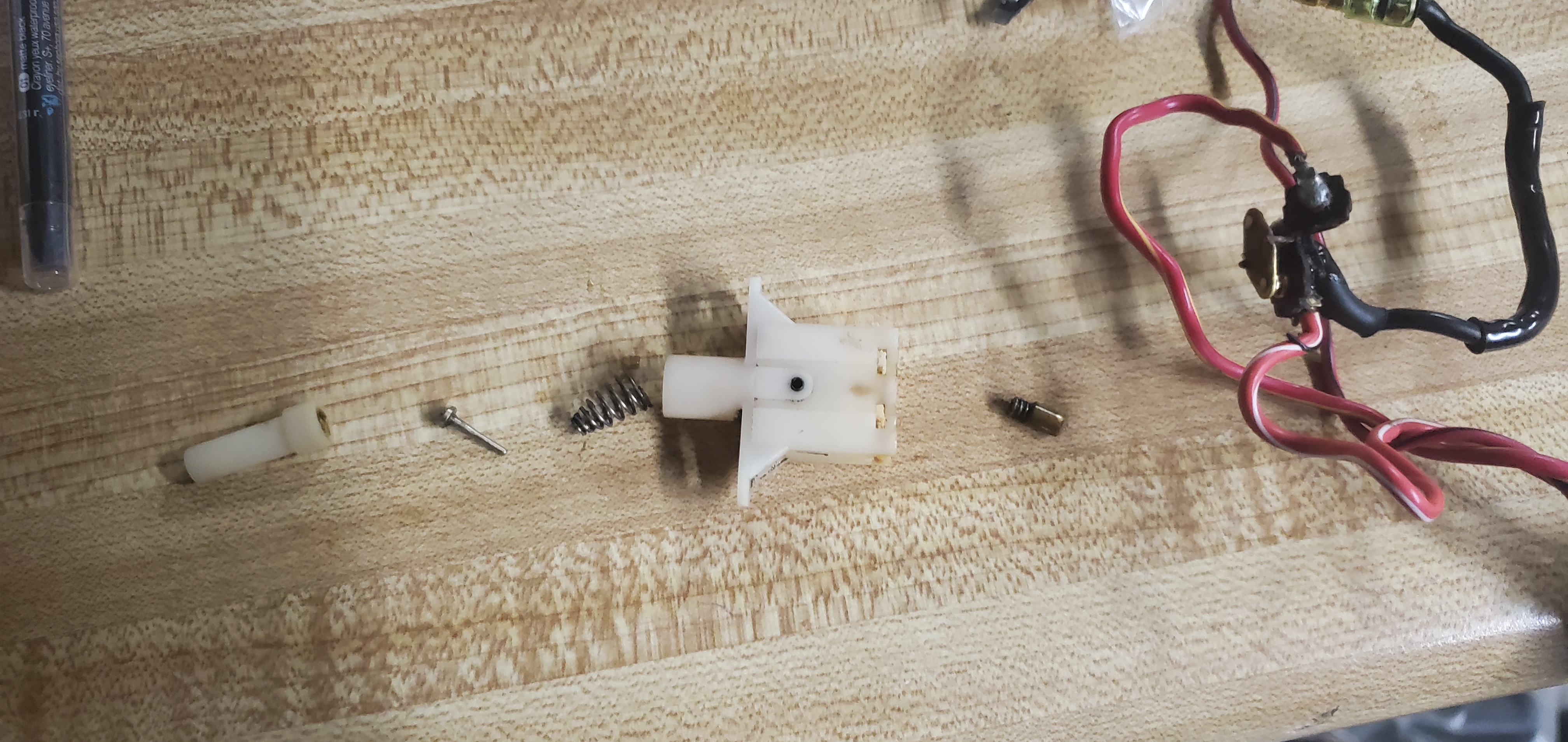
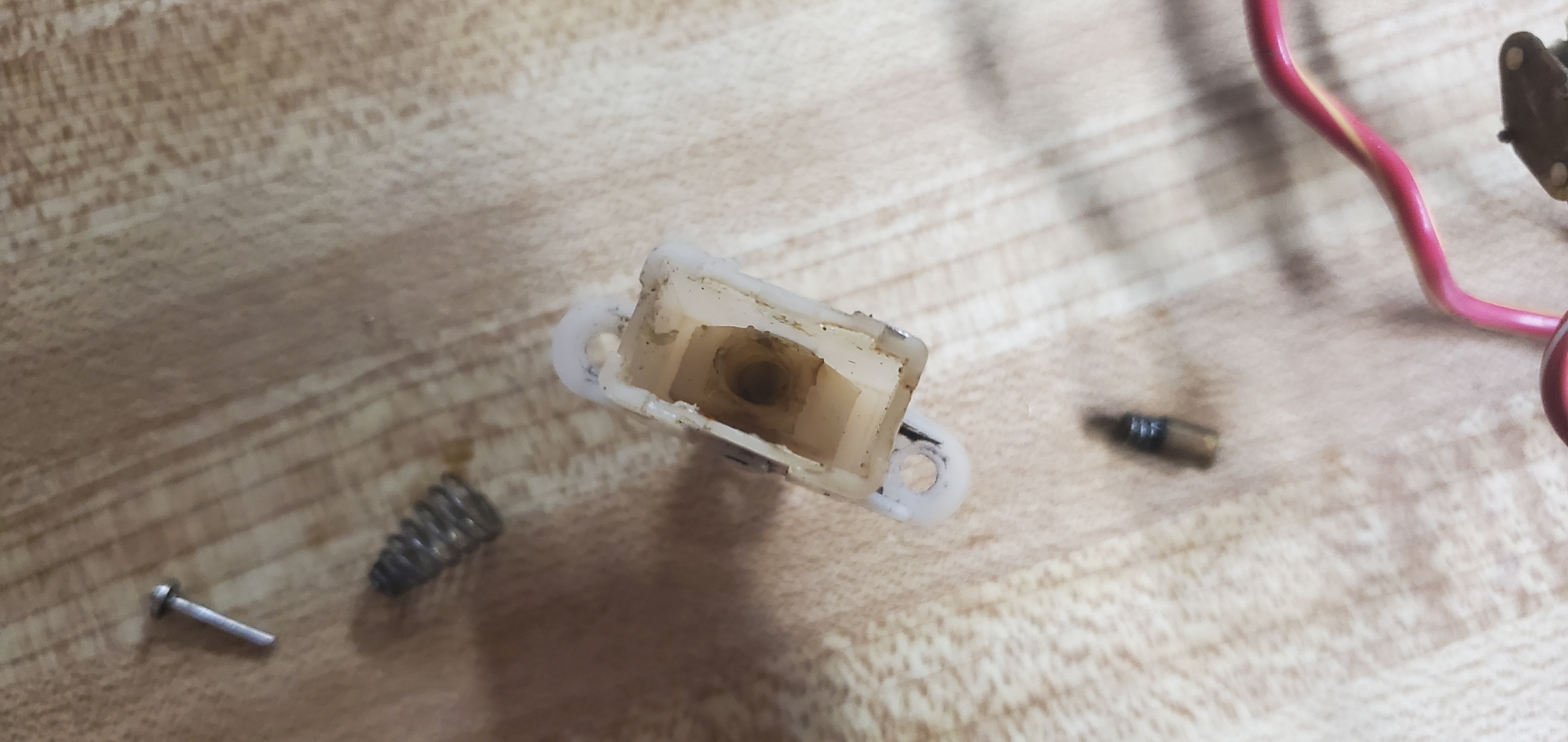
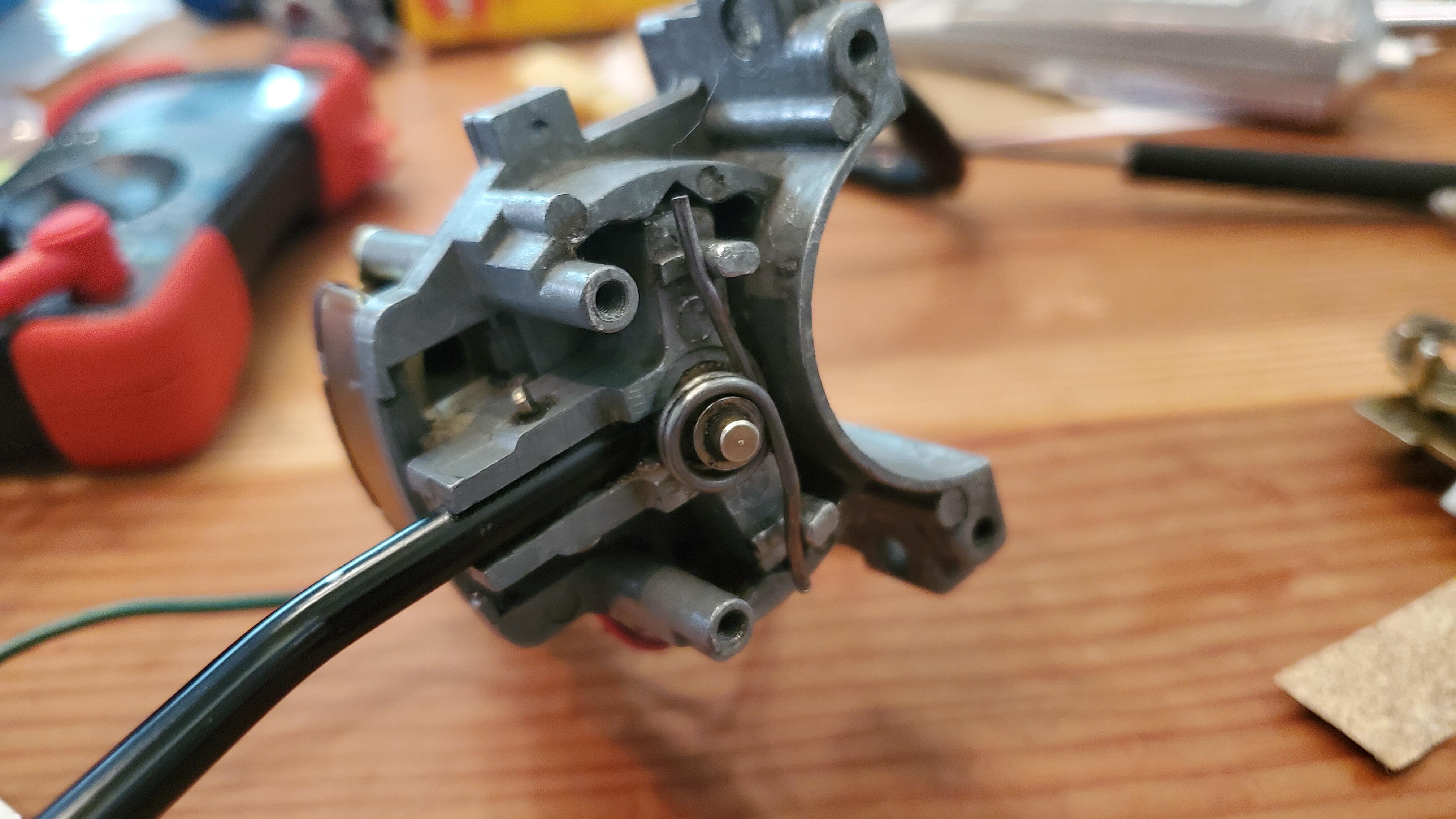
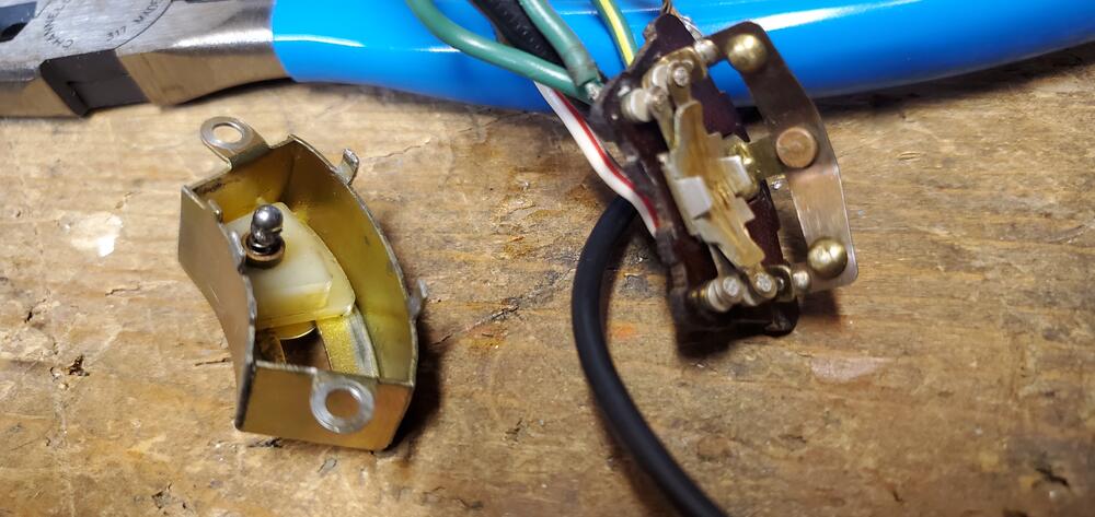
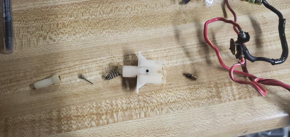
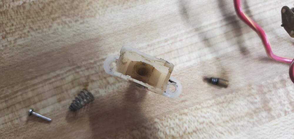
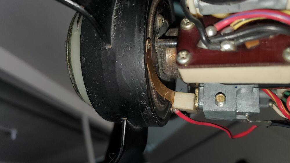
Hey, working on restoring my turn/headlight assembly on my 73 and hadn't really found a tear down of the high/low beam switch so I figured I'd post some pictures while I'm at it The spring in the pin on the right is removable, i just didn't want them rolling away so I kept them attached. Inside the plastic housing is a plastic triangle that the pin actually switches other end to the left or right side when you depress the switch. It's held in by a retaining pin but I didn't want to push my luck trying to get that out. At the tip of that is the spring and brass top, which is rocked back and forth against a little plate which connecst the circuit to the high or low beam. The bits on the right side of the picture are the high/low beam wiring (red/yellow and red/white wires) and the incoming power signal (black wire). Here's a picture inside the switch housing: The spring and cap go in the hole in the middle there. When you depress the switch, that pin on the left pushes against that white plastic piece and moves it to the left or right side of the housing The actual rocker switch. The one in my car was broken into 3 pieces. Previous owner tried to glue them together but it eventually failed. For now I'm just going to try and glue them back together. That little diamond shaped plate rocks back and forth. Normally it will be pushed to once side and the circuit will be closed for low beams, and when you depress the switch the rocker will move to the right and depress the other side completing the high beam circuit. I hadn't seen pictures of one of these apart so just sharing what's inside there. Two quick question I had: 1). Are the red/yellow or red/white wires supposed to be for the high or low beam? I need to figure out which is high/low beam so I can make sure I orient the thing the right way when I put it back together 2). It seems like the high beam switch is only temporary as the switch resets after you let go of it. Is that correct? ie, in a modern car, you can pull for temp high beams, or push for hold high beams. It seems like the 240z is setup so you can pull for temp high beams but there doesn't seem to be a way to keep high beams on?
-
I bought an assorted kit of stainless steel ball bearings that include 2.5, 3, and 3.5mm so I think one of those should work. I'll follow up once I get them and try them out
-
I measured the hole that the spring slides into and thats 3mm so I'm probably going to try and find one that size, under the assumption that the ball gets recessed in it a bit
-
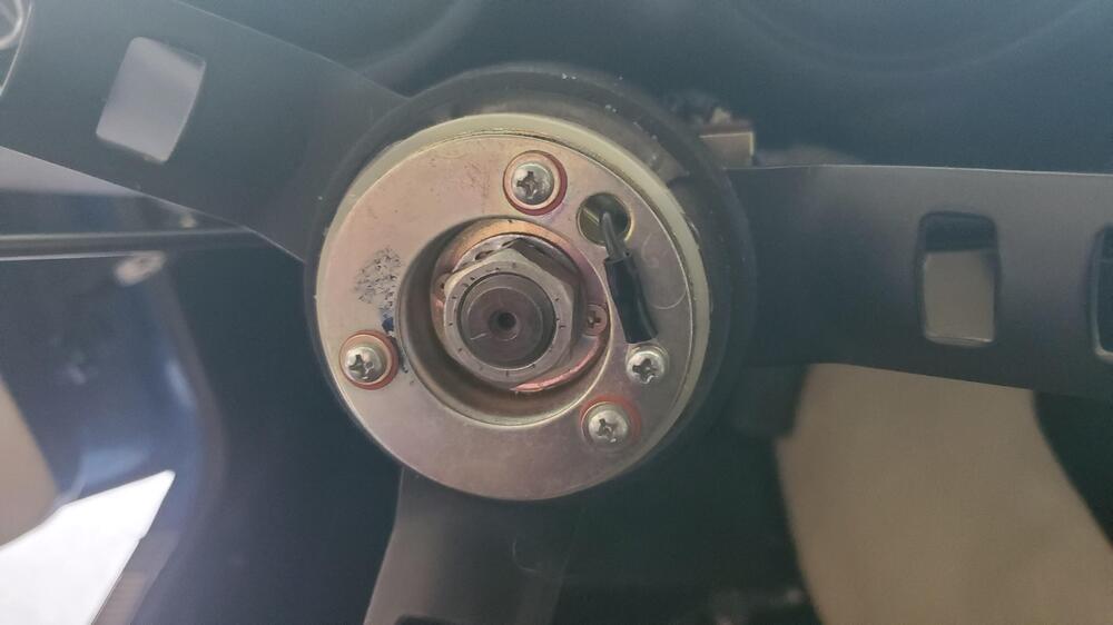
Hey, the turn signals in my 73 240z have been intermittent and I finally decided to bite the bullet and try and separate the turn signal assembly and I noticed that the little ball that's supposed to be on the end of the spring was missing. Basically #2 in this picture Anyone have any idea what size that is? It might just guess and try and buy a few small ones
-
I connected a ground strap to the ignition switch and that grounded the column and the horn worked then (which is how I ID'ed it being a grounding issue). I also agree in that I'd expect the center shaft to be grounded via the bearings since they are metal. American cars of the period would use a metal bearing in a rubber sleeve so it makes sense why those needed a grounding strap. I don't know if the housing was painted or what as it doesn't seem to be grounded through the housing
-
I definitely thought the same thing but it looks like that coupler is a pretty common ground approach for 60s/70s vehicles (American ones at least). The column might get ground from where it's bolted to the firewall as it looks like the steering column bearings aren't rubber coated like some other steering columns from the period so there should be some contact there I know the entire column is isolated from the dash mounting bracket as that mount has a rubber gasket so it shouldn't touch the column housing
-
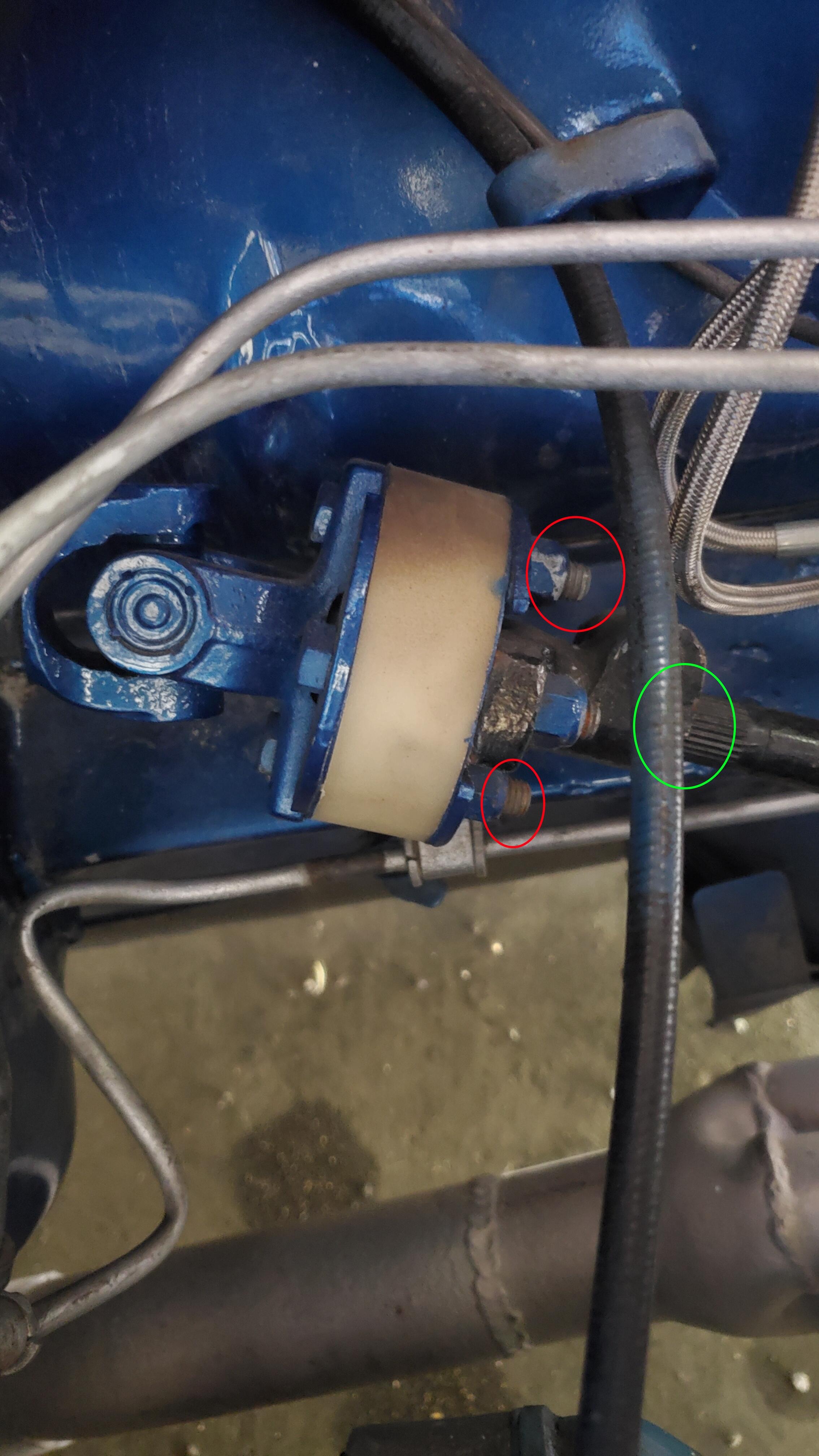
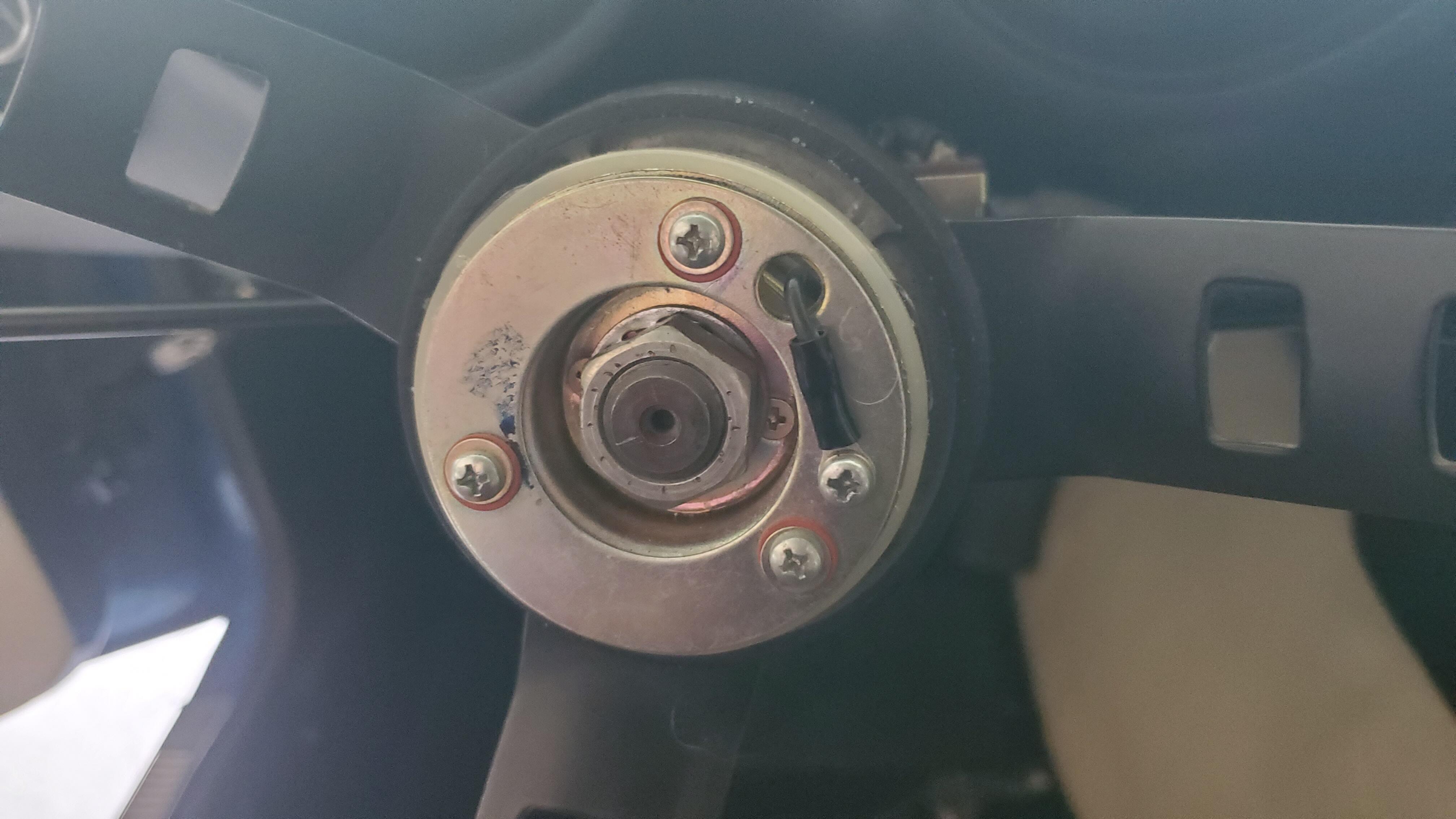
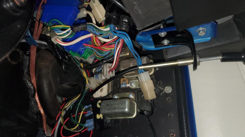
Taking that resistance reading with the ignition in the lock position it reads .2 ohms. With the key in the ACC position it reads about 8 ohms The car was restored in ~2010 and they painted a lot (which is why I've been trying to track down what should be the source of ground). I was poking at the steering coupler and the column does have continuity through the coupler but it doesn't have continuity to the input shaft to the steering box (that does have ground though). I'd guess it's because a bunch of this stuff has been painted over I've attached a picture to try and help. The red circled bolts have continuity with the steering column. The green part has continuity to ground. I think there should be a connection between the two where the steering box input shaft is bolted to the H section of the coupler. The H plates have been painted blue so I'd guess that's why there's no continuity there. I think the "proper" solution is to probably take those coupler plates off and make sure there's not paint preventing contact, but the easier solution (and what I'll probably do) is just buy a short grounding strap and connect them that way

-
Finally had a chance to get to this today. The ground strap is there but it's connected to the starter starter but there are a few small ancillary grounds that do go to the body. @SteveJ I tried checking for continuity from the spots you indicated on the column and no bueno. I'm not sure if the column ground is supposed to come from where it's bolted to the firewall, the metal bulkhead, or from the steering coupler in the engine bay. I thought the columns were generally grounded through the steering coupler joint as the column was generally isolated from the column tube. I'll have a little more time tomorrow and might start poking at that
-
Thanks for the explanation @SteveJ, I'd been doing some research today and went over something similar with a buddy so it makes more sense now. Thanks for the ground check spots. I can try checking that tomorrow.
-
Thanks @cgsheen1, that's what I initially thought. I can't confirm if the frame ground is intact but I would assume so. I know it was common to ground columns around that time via the rag joint for the steering column so I was going to look into that next. The rag joint parts and the column are painted so I was gonna check if something wasn't able to ground because of that. Another question I've had some trouble trying to confirm looking at the wiring diagrams: should the red/black wire that connects to the brass arm that touches the steering wheel have 12v power or should that be purely ground? Mine has 12v so when I press the horn button (grounding the "column" via the ignition switch bracket) I get a small spark which makes sense in that context, but I would have thought that would all just be a ground circuit with no power
-
Ya, I checked that and there isn't continuity I'm just not sure how the column is supposed to be grounded
-
For the column grounding, is it generally grounded via just being bolted to the body or is there supposed to be an actual dedicated ground wire? An easy solution would be to run a ground wire from the ignition or turn signal/light stalk to the metal dash bracket which is grounded. Something else I noticed is there's a slight spark when the column is grounded and I press the horn plates together. That makes some sense since the red/black wire has 12v that touches the back of the steering wheel, but I would have thought that's just completing a ground circuit and there wouldn't be a spark. Any idea what's going on there? (I'm mostly just curious and definitely not an electrical expert so it just seemed a little unexpected) <- Thinking about it more, that makes sense. I figured I'd leave the info there if it helps anyone else though
-
I took a look and don't see any loose wires. That was mostly looking at the column itself. I didn't get way into the footwell to look under the dash
-
Circling back as I've finally had a chance to look at this. I can confirm the horn relay works. If I remove the ground (GB wire connected to the S terminal on the relay) and directly ground it the horn works. I also independently tested the relay and it worked as well So the problem appears to be the ground path isn't being completed. There is continuity from the GB wire at the relay to the horn switch (I checked the black wire on the front and the flexible brass arm on the back). I don't remember how I tested the column originally but I can confirm it *doesn't* have ground. If I ground the steering column (just clipping a ground wire to the ignition switch from the battery) and hit the horn it works as expected. Does anyone know how/where the column is grounded? Is it just by being bolted to the frame or is there an actual ground wire that should be connected somewhere? I would assume its the former and so maybe there's some paint or corrosion preventing that
-
I got under the car and took a look at some of the other hoses and while not leaking look a bit cracked. The OEM hoses are a bit too pricey for me so I'll probably drop the tank at some point and replace all the hoses with off the shelf fuel hose
-
Thanks guys, this car was restored around 2010 but was sitting for a while before the last owner sold so I don't think all the hoses are quite that old. I understand how the hoses run and how to replace them, I just wasn't sure if I could replace just that rear evap hose without dropping the tank and couldn't find an answer on that. The job itself doesn't look too bad outside if the hassle of it haha I was looking at using a unicoil to make the 180" turn for the rear hose. I don't think I want to spend the 80 bucks on a oem (ish?) replacement
-
Hey, I went to try and fill my 240z to a full tank for the first time and after putting in ~5.5 gallons (from a little under 1/4 tank on the fuel gauge) noticed a decent amount of fuel coming out the bottom of the car. I got underneath the car and noticed it was leaking a lot from the evap hose at the top/rear of the tank. The hose looks a little kinked and it looks like it was pouring out from where it was kinked. It was leaking down from that spot to the front corner of the tank and down from there. I *think* that's the only source of the leak. The car leaked for quite a bit before it finally got below the level of that hose and stopped. The fuel gauge is sitting at just under 3/4 of a tank now. I've been reading through a few threads and haven't quite found answers on these but I have a few questions: 1). The car is pretty new to me so I don't know how accurate the fuel gauge is but if it's leaking out of that evap hose, that basically means the tank was fueled to full right? Was it overfilled at that point? 2): Can I drop, but not remove, the tank to replace the hose? Thanks!
-
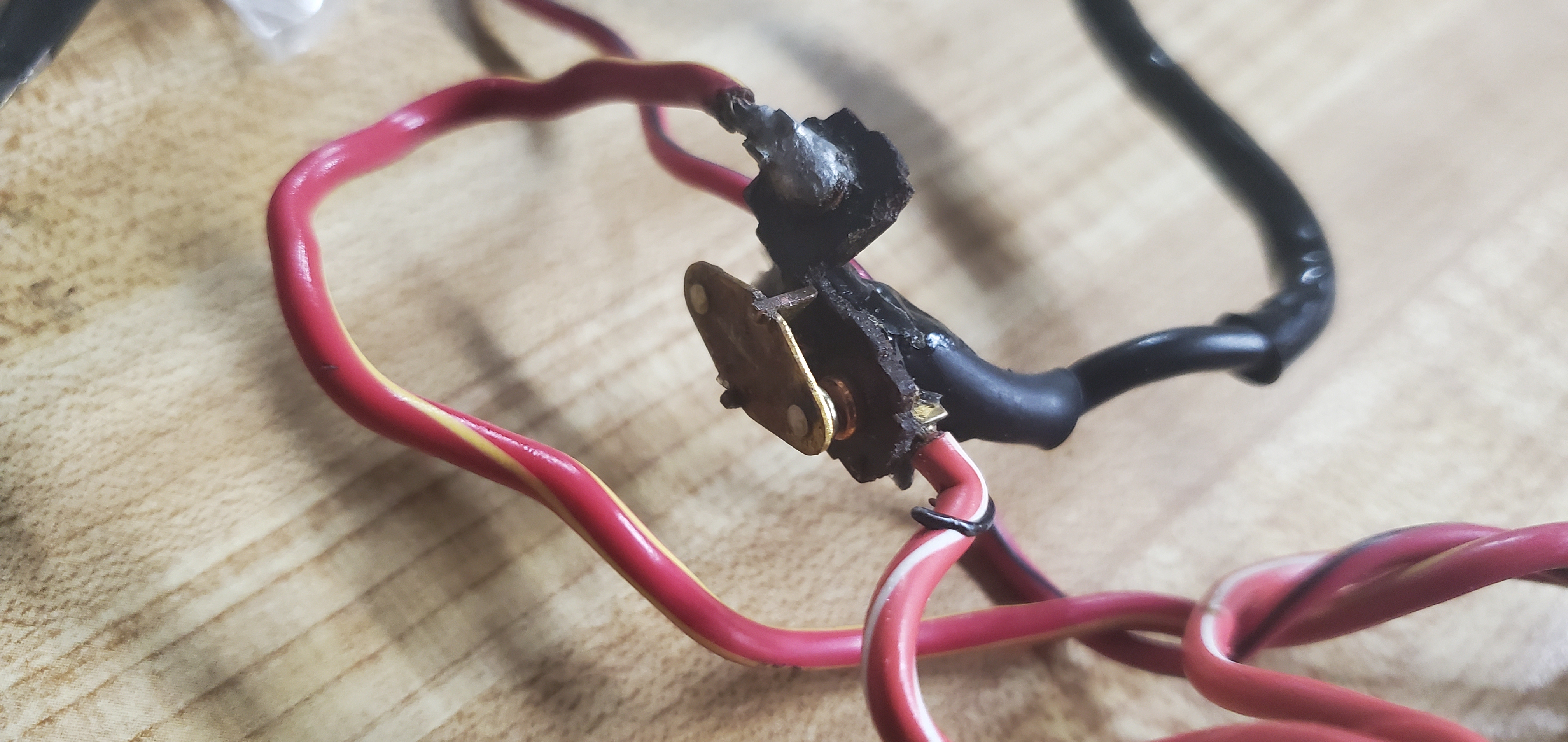
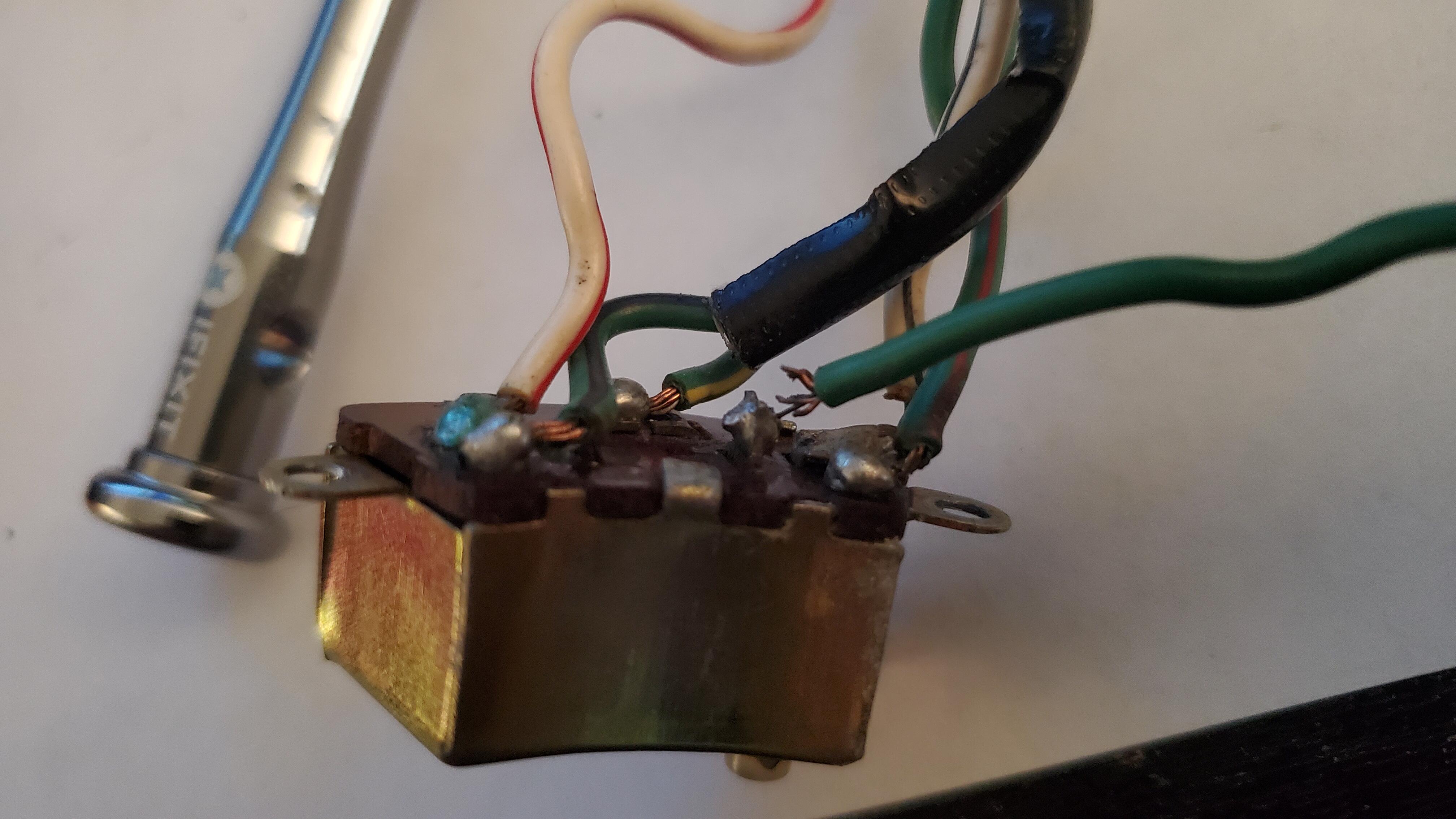
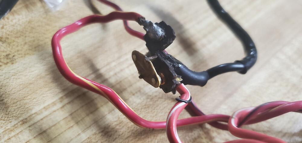
Just wanted to circle back on this as I wrapped this up today. Someone has definitely been through this switch before. I really wanted to take the switch box apart and just adjust the contacts inside, but the tabs already looked a bit cracked and I didn't think they'd survive another round of opening and closing so I was looking for a different fix. I could peak through the opening and things looked pretty clean and fresh though so it might have been refurbed by the PO I got the stock on the bench and first thing I noticed was the 12v supply had a terrible contact (you can see it hanging on by a literal thread here). That's the 12v supply so I wonder if that impacted the relay at all A simple way to test this is hook something up to that 12v source wire (the solid green wire there) and as you move the switch at the bottom you should have continuity between the left and right signals. After fixing 2 more bad contacts everything was working well with the box on it's own but after I installed it back in the stock not all the signals were working After fiddling for a bit I noticed that the turn signal stalk itself wasn't traveling the full length of switch so it wasn't activating the signals like it was when I tested it on it's own. I could really push on the stalk and it would activate them but it didn't feel right or natural I eventually noticed that this spring, which butts up against the turn signal reset mechanism (the gold ratcheting bits you see in turn signal assembly but they are removed and to the right here), was what was limiting how much travel the switch could make. I initially started by grinding the bottom pin a bit to give it a bit more space which helped a bit, but it was still intermittent. Eventually I just took the spring off and bent it to loosen the tension and that resolved the issue! The switch is now super easy to activate and all the signals are working.


-
Perfect, thanks.
-
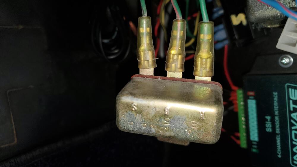
Hey, next up on the electrical list is the horn and I've hit a bit of a wall. If I push the horn I get no noise and no noticeable relay sound. First thing I did was check and swap the fuse and no difference. My column does have the brass arm contacting the steering wheel and I do measure 12V on the red wire connecting to it. I tried measuring the voltage at the horns alone and didn't get any voltage but I'll try and confirm when I can get a friend to help I also confirmed that when pushing the horn button that the horn switch does get grounded. To me it seems like an issue at the relay which I want to check next. Looking at the the FSM it says the horn relay should be in the right dash side panel bracket, which I assume is the set below. I don't have much access to that side of the car, but if this is the right area, which of these switches is the horn relay? I think the bottom one is for the wipers. The left is the front of the car and you can see the closed passenger side door card on the right Thanks!
-
Cool, thanks for the suggestion. Thanks again for the help too. One electrical thing on it's way to be sorted and then on to the next thing haha