


Zed Head
Free Member
-
Joined
-
Last visited
Everything posted by Zed Head
-
 I just read through that last thread again and it's pretty scary. Be ready to break a sweat just reading. The incredible expanding project...
 -
I found the thread I was thinking of. It's actually just a portion of a longer thread. The weirdness starts at post #24.
-
Can't find it but this one is interesting -
-
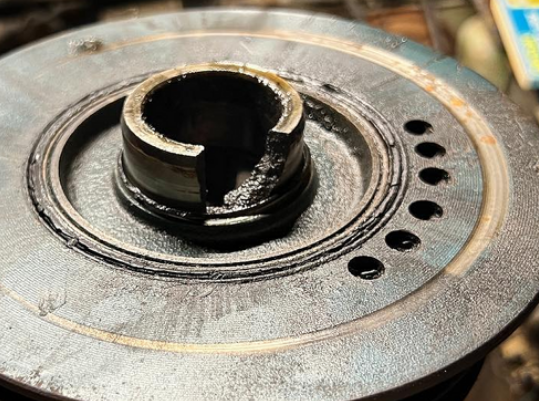
Things will get more clear when you get that used damper and test fit it. The woodruff keys are available. There is a recent thread on the forum from a guy who was having trouble getting the damper on without pushing the key out of its slot. Some good details in it, I'll see if can find it. I wonder if those seal parts that you found aren't from a previous seal. That's a 280ZX damper on a 260Z. Somebody's been in there before. Here's the part number for the woodruff key. #10. Search the part number and you'll get lots of hits. Your local auto parts store might even have it. http://www.carpartsmanual.com/datsun/Z-1969-1978/engine-240z-260z/piston-crankshaft
-
The fracture surface looks oily. And not seeing how you get that "pointer" groove without some wobble. Could be that the damper rubber is gone. Who knows. We need to know.
-
More problems > more fun. Not kidding!
It happens.
Why is it so rusty on the inside surface, the eBay piece? Looks like it's been off and wet for quite a while. Where does the fracture start on the damaged damper? Is it at the keyway? How does the end of the crankshaft look? Better take a close look. That groove in your picture looks like the damper was cocked on the shaft so bad that it rubbed on something, like it was wobbling You might have bigger problems. (Sorry). That's a bummer. @Terrapin Z has many parts. Maybe he has a two row damper. Good luck.
My post about the relay was meant only about taking the load off of the power supply switch, which has the plastic nubbin melting problem, and the solder joint breaking problem (which the new brass piece won't fix. It will still get hot). I haven't seen any overheating problems described at the dimmer switch, which is where high and low are separated. Zs-ondabrains setup had relays on both ends, I thought. Might be worthwhile to go back and look at his work.
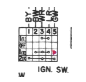
Here's something funny though. This number is for a later model switch. Not a 240Z switch. So, G/W and B/W are already connected at Start (I assume, like the 280Z switch chart). Maybe just getting a 280Z switch will solve the problem. Time to plug it in and see what happens. https://www.rockauto.com/en/partsearch/?partnum=48750-e7705 https://www.classiczcars.com/forums/topic/58568-duffys-171-series-1-240z-build/?page=36#comment-644653
Well, overall, I think the good news is that the problem has been defined and several solutions have been offered. The reason for the power loss seems clear and it should definitely be possible to remove that problem. I'd just try SteveJ's solution at the ballast resistor first. It's simple and it will most likely work, proving the circuit, then you can decide if you want to go farther. I learned something about the Nissan ignition switch illustrations. I need to go out and see how they do them today.
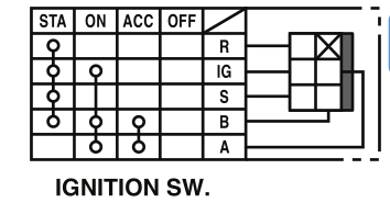
Earlier I said that the Accessory pin would be powered if you did that. I think that I misunderstood how the switch works on the inside. The diagram is misleading. It looks like a circuit illustration but really it just shows what's connected to Battery at any position of the switch. Sorry about the confusion. If column #4 was connected to column #2 you would not be able to use Accessory alone, without having power to the the Ignition circuit. Therefore they must not be connected. Is there an effort here to keep the original wires intact? Seems odd to have powered wires run all the way in to the engine bay that don't actually serve their original purpose. I think that you could connect the pins on the back of the switch and achieve the same result as connecting them in the engine bay. A simple back probed jumper at the connection.
Here is a 1976 280Z. 240Z next to it. Ig and R ((R)esistor/ballast) both get power on a 280Z switch. I'd test that switch's Ig and R pins and see what kind of switch you have. See if Ig and R both have continuity at Start. I thought this was a simple problem but it's really not. Maybe that's why they changed the switch, and the wiring.
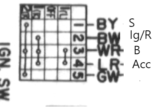 I picked the S circuit just because it was the first thing that came to mind. Wrong, pretty sure, the stuff below. Corrected farther down the page. If you connect GW and BW then you'll be backfeeding the Acc circuit during Start. #4. IF it's a 240Z switch. Check out the 1976 280Z switch in the next post.
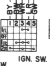
 I think that you're back to the original point of your quest. You have a new switch now and you know how it functions. "Best" is very subjective. I think that the "key" point here is that you have the possibility of continuous power from the ignition switch from On to Start and back to On.
That seems to answer the "bump" question, that would be the bridging point inside the switch. Seems like you could run a wire from the Start circuit to the ECU power supply and it would work. Probably need a diode so that you don't backfeed the Starter circuit through the On position. Similar to the 240Z alternator swap problem. You could also just add a separate power circuit for the ECU, with a switch or button. Might be good theft protection also. Or does this go all the way back to the original power supply wire problem? The overloaded wire. SteveJ's solutions. Anyway, there are several solution possibilities. Relays are your friend when you're adding new loads.
1978 has two. They're green. The best guess seems to be 40 amps.
I think that you're back to the original point of your quest. You have a new switch now and you know how it functions. "Best" is very subjective. I think that the "key" point here is that you have the possibility of continuous power from the ignition switch from On to Start and back to On.
That seems to answer the "bump" question, that would be the bridging point inside the switch. Seems like you could run a wire from the Start circuit to the ECU power supply and it would work. Probably need a diode so that you don't backfeed the Starter circuit through the On position. Similar to the 240Z alternator swap problem. You could also just add a separate power circuit for the ECU, with a switch or button. Might be good theft protection also. Or does this go all the way back to the original power supply wire problem? The overloaded wire. SteveJ's solutions. Anyway, there are several solution possibilities. Relays are your friend when you're adding new loads.
1978 has two. They're green. The best guess seems to be 40 amps.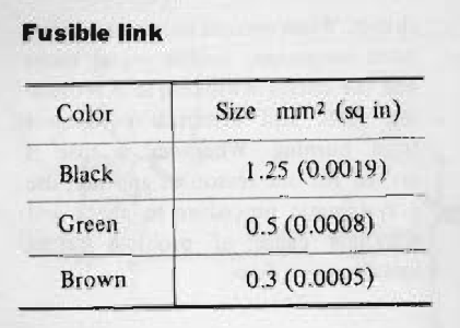 You posted in the 1975 "strange intake noise" thread. I used the 1975 FSM. Still - wrong test method. There is no method for measuring resistance across the vane sweep.
You have the wrong picture with the test method. The picture is for a single resistance measurement, not vane movement. Here is the correct picture. Terminals 7 and 8. And you're looking for smoothness of the voltage reading, not resistance. Page EF-51 and 52. p.s. you should not sand the carbon trace. It's not very thick, you could ruin it.
You posted in the 1975 "strange intake noise" thread. I used the 1975 FSM. Still - wrong test method. There is no method for measuring resistance across the vane sweep.
You have the wrong picture with the test method. The picture is for a single resistance measurement, not vane movement. Here is the correct picture. Terminals 7 and 8. And you're looking for smoothness of the voltage reading, not resistance. Page EF-51 and 52. p.s. you should not sand the carbon trace. It's not very thick, you could ruin it.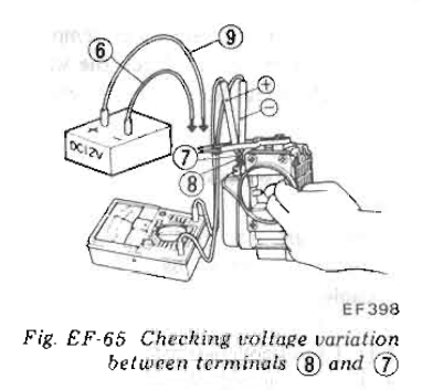 Looks used. Are you trying to find out if it's good? The larger bore will actually create less pressure. It's bigger because the ZX's had rear discs.
My comment about capping the blue wire in the engine bay wasn't right. You need it on the coil. So you'd just cut the tach branch off of it and use the branch for the trigger wire. Seems like all of the needed wires are almost ready to go. It will all make sense once it's in hand. Looks like SteveJ is trying to get to plug and play, with connectors and all. I'd probably just set up a terminal strip. Anyway, don't forget to position it so you can see the adjustments. Good luck.
Looks used. Are you trying to find out if it's good? The larger bore will actually create less pressure. It's bigger because the ZX's had rear discs.
My comment about capping the blue wire in the engine bay wasn't right. You need it on the coil. So you'd just cut the tach branch off of it and use the branch for the trigger wire. Seems like all of the needed wires are almost ready to go. It will all make sense once it's in hand. Looks like SteveJ is trying to get to plug and play, with connectors and all. I'd probably just set up a terminal strip. Anyway, don't forget to position it so you can see the adjustments. Good luck.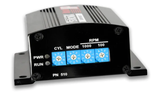 That seems right. You'd have to guess that they were aware of the tach problems with the MSD boxes and engineered a "tach adapter" right in to the system. Looks like the same signal that the old ignition module would deliver. On-off-on-off...12 volts. The blue wire is branched at the ignition module. You might be able to just attach the old ignition module blue wire at the Pertronix box, since it's there, (Edited >and cap the blue wire end in the engine bay.) Not clear if the 2200 ohm resistor is needed. Probably won't hurt, it's good insurance against shorts. Stuff to think about.


Important Information
By using this site, you agree to our Privacy Policy and Guidelines. We have placed cookies on your device to help make this website better. You can adjust your cookie settings, otherwise we'll assume you're okay to continue.