


Zed Head
Free Member
-
Joined
-
Last visited
Everything posted by Zed Head
-
 I probably planted the wrong seed in your brain when I said C and E. You want to check voltage on C, and continuity to ground on E. Which you did, directly, and in one step with your method.. The voltage was on C and the path to ground was on E. So those numbers look right. But they don't tell you about the "B" circuit. You're at the point where you'll probably find that a replacement ECU will get you running. Then you'll have to decide if you want to try to fix the ECU. Yours is the first 3 injector problem I've seen. It implies that one of those transistor "B" traces is bad. It seems like the "B" timing circuit should be common to both, otherwise there would be two complete sets of timing circuits, which seems overkill and redundant. So, tracing the two transistor "B" circuits back should find a break, I'd think. My inner engineer is curious. Don't throw the ECU away if you get a good one.
 -
Actually, the C voltage fits what you saw at the ECU connector. The E voltage might be through one of those resistors CO mentioned in that other thread. You can see full voltage if very little current is flowing. Did you check for continuity to ground on the E pin? You can do that with the key off. Anyway, the reality is it doesn't work. The very last thing that Nissan says after all of the other tests fail is "replace ECU". Try a loaner first, then you'll know if you should buy.
-
Did they fail in the same way? CO knows his stuff. I'd take him up on his loaner offer. Maybe he'll swap that transistor for you just to see what happens . I'm not sure but I think that the transistors should have a direct connection to the injectors. You should be able to take a meter and see voltage on the "C" leg, I believe. It should be hot when the injectors are, and the "E" leg should be connected to ground. "B" is the activater, controlled by the timing circuitry. (Give me a grade CO...). So you can check C and E by plugging in the ECU and turning on the key. Be careful with the meter probes.
-
The gasket alone, dry, should be fine on the cover. On the bolts, make sure that there are no burrs on the mating surfaces from past lock washer damage, clean them up, scrape off damaged paint (Nissan clamped directly on fresh paint but it tends to chip off after disassembly.) and don't use any thread locker. Make sure the lock washers are in good shape. But new ones if you're not sure. Some of us (me for sure, I think others) put a spongy material in the cover vent to stop oil droplets from leaving and oiling up the diff. You might consider it while its apart.
-
I have a vague memory of exploring the source of those O'Reilly's heads in the past. I think that they source them and rebuild them when orders come in. I just called O"Reillys and asked about one. They said that they special order it from Power Torque and it should show up in one week. I got on the Google and found these. Very recent. There's always somethin;... https://power-torque-engines.pissedconsumer.com/ http://www.bbb.org/dallas/business-reviews/engines-rebuild-and-exchange/power-torque-engines-in-grand-prairie-tx-90405420/complaints Hate to be a downer. They might do great with high volume stuff like small block chevys. So many ways to go wrong with the L6 head though. Cam lobes, valve seats, cracks...
-
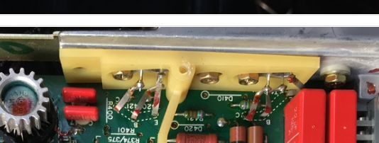
The 11 600-000 number looks right. You have what might be a second source ECU, or a replacement, from Bosch, with a "K" instead of an "A". You got a picture of the bottom of the transistors. They're above the picture I cut out of yours. You can see the ribbons. The screw heads are of the screws holding the transistors. Here's a copy of the ECU guide, showing the Nissan "A" numbers.
-
You're unlikely to find a place that has rebuilt 5 speeds "in stock". Your best route will probably be to find a decent used one and take it to a shop that knows what's what. And that 5th gear would be a .745. .75 would come from your rounding method, which can vary depending on profession.
-
It's a perfect bathroom library book. You can learn something in just a paragraph. Don't even want to think about mobile phone/super computers in the bathroom...
-
Post #37 here has the part # for the transistor - http://www.classiczcars.com/topic/56143-super-rich-plugs-fouled/?page=2 You can also read our past ramblings, insights, and conclusions about ECU problems. Might be entertaining.
-
I'll dig up the number. The connections from the transistor pins to the board are fairly fragile looking metal ribbons. Very easy to see, the two transistors are on the top edge of the assembly. ~Quarter-size. I could see one of the ribbons getting damaged if somebody poked around in there. You never know. Besides that, you'll want the part number for the ECU. There are several.
-
You might want to wait until you know which camshaft you'll be using before you buy lash pads. If you get a reground cam profile, the lash pads will be different than with a stock camshaft. Also, waiting until the head has been inspected is a good idea too since it's possible that it's warped or cracked or eroded internally. It might not be worth rebuilding. The basic process and steps, in order, is/are described in the "How to Rebuild" book that site linked to (which you really should have bought before you even started. It's very thorough). If you find the right shop/mechanic they'll know the details of lash pads and rocker arm wipe patterns and other details. If you get the wrong one they might try to guess their way through and they can make a mess of things. Somebody on another forum got a single bad/tight rocker arm and ruined his camshaft. When things are right they're very durable. When things are off, they can fail quickly.
-
Just for fun, you might take the ECU cover off and make sure the transistor wires are intact, and/or not shorted. The ECU location can get moist if a leak develops at the windshield. I actually have some part numbers for a replacement transistor and did replace both on a bad ECU. But probably for the wrong reasons, they tested okay afterward. It was probably something else. Your situation though, with three dead injectors, looks like maybe a single transistor or its wiring.
-
That looks like the replacement relay for the original JECS relay. Which is actually based on the Bosch system. It's actually two relays in one, EFI and fuel pump. Despite all of the pins it's a fairly simple relay. If you get the readings that you should at the ECU connector, don't worry about it. Many people "assume" and replace, it's hard to resist. If you get tricky, you can ground the injectors individually at the ECU connector, just like it would, to test the complete circuit of wires, power and injectors. I made some male pins to use in the connector from a flattened piece of solid core copper wire. Makes it easy to get an alligator clip connected to supply power and ground. Forgot to say - there's a procedure for testing the EFI relay, if you get odd numbers. In the FSM, Engine Fuel chapter, and probably in that EFI book too.
-
You can check for power at the injectors with the key On, with a meter or test light. I think that power is supplied in a set of two and four. But it's grounded through the ECU in sets of three. So you might have an issue with the ECU. If you have a meter, going through the tests in the EFI Guide is the way yo do things. It's what's happening at the eCU that really matters and most of the tests start there. The 1980 EFI guide (in the Downloads section) covers all years up to 1981. Use that one.
-
You were almost to a good conclusion. When you put the 3 rear connections on the 3 fronts, did the 3 front cylinders start working instead of the back 3? Or did the same cylinders work, just with different connections? If the cylinders that work follow the connections, then it's a connection problem. If they don't, it's a spark or mechanical problem. These engines will start and run with the firing order of the plug wires backward. They sound like they're running on 3 cylinders when you do that (by accident, of course). Finally, history of the engine helps. Did it ever run right, as far as you know? Edit - sorry for the ad. It came with the edit box.
-
This seems a bit presumptuous. You have the need.. Seems like this would be a place where some ingenuity and some LED bulbs could result in an improved system. Maybe even a light with a focusable lens, like the LED flashlights. The stock system really isn't a lot of help, especially n a metro area where the street lights cause sharp shadows.
-
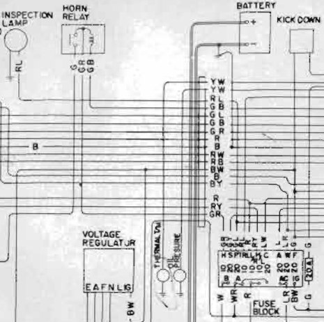
BE-6 has a nice wiring diagram. Shows a red w/blue that powers the inspection lamp.
-
I've had numerous problems with my gauge lights. The sockets get screwed up and the contacts in the socket don't make good contact with the bulb. MSA's replacement bulbs were too big and rubbed on the inside of the housing. Some of the sockets have a ground wire attached to the socket itself, some of them ground through the edge of the mounting hole. Generally, the gauge lights are pain and require special attention to get working right, and installed without knocking something loose. My complaint might not help you but the point is it could be one of several different possible problems with each bulb. I had to go through each socket individually. And one of them still is intermittent.
-
p.s. most mechanics today will assume that the ECU has sensors for every component and use an IACV and/or ignition timing to control idle speed. The early EFI system is very primitive and hard to comprehend for today's code readers. The components mostly work independently with the engineers assuming that each individual component is adjusted to a certain specification. Very little adjusting to conditions, besides the coolant temperature sensor. They're very close to being electronic carburetors.
-
-
-
Sorry, and again, no offense, but until you turn that screw 1/2 turn and go out and show that it causes the engine to fall on its face again, you're just guessing and believing "mechanics" who probably don't really understand the engines. This - "When the car is cold and being enriched by the air regulator being open, it detects that and doesn't operate the same as it does when the car is hot and not under enrichment." and the "no doubt" cause a lot of doubt out here. Your conclusions and understanding are not right. The AAR is on its own circuit, the ECU has no idea what its doing. As I said, no offense intended. Thanks for sharing your observation. Go turn that screw 1/2 turn, you can do it by hand, and see what happens. The idle speed will increase slightly and that's all.
-
No offense, but it's probably just a coincidence. The proper way to tell if the "full enrichment" was happening would have been with a meter, at the ECU connector. From an experimental perspective, if you want to verify that the 1/2 turn of the screw was the cause, you would turn the screw back to where it was. The problem should return. The idle adjustment screw just controls an air passage that lets air past the throttle blade. It's the one with the big head and the spring underneath the head. Could be that your distributor breaker plate is sticking, and it broke free when you were testing. Just one possibility.
-
These old EFI systems tend to run lean once you get all the bugs worked out, ofent it's so bad that you'll get popping back through the intake. I have a method of richening the mixture and I can get a misfire/stumble if I have it set too lean. You could try it, it's pretty easy. http://atlanticz.ca/zclub/techtips/tempsensorpot/index.html The electronic ignition modules fail also but that problem tends to be more obvious than what you're describing. I'd try the the "fuel tweak" first. I have mine mounted in the cabin so I can tune it to the finest level. It makes a difference.
-
Nice. If you lower the car just a bit it will help the handling a lot. I've heard/read that the later cars sit a little high because there's certain height the 5 mph bumpers have to be at. Federal guidelines. Only mentioning 'cause you're going to work on the suspension.
