


This forum has been very helpful to me. As a means of documenting some of what we have done and to help others avoid some of my mistakes I thought I would post the installation of a vintage gen II mini AC system.
Background:
My son and I are restoring a 1973 240z. We call it the bucket, as there was a significant amount of rust that had to be dealt with and our other choice – Money Pit was already taken. We are changing the color from 113 avocado green to mango orange, it has an L-28 engine and a 5 speed gear box.
At this point:
- the car was taken to bare metal, metal replaced where required and any rust has been eliminated
- the rear clip is painted,
- front and rear suspension has been restored/upgraded and installed
- brake system has been restored/upgraded and installed
- half axles, differential, driveshaft, transmission, engine have been restored/upgraded and installed
- fuel system has been restored and is installed
- cooling system has been restored/upgraded and installed
- electrical harness has been restored/upgraded and the cockpit harness is installed
When we purchased the car, it did have a non-working aftermarket AC system, probably installed at the dealership. We decided to replace the AC, defrost, and heater with an integrated system from Vintage Air.
Vintage Air recommended a Gen II Mini
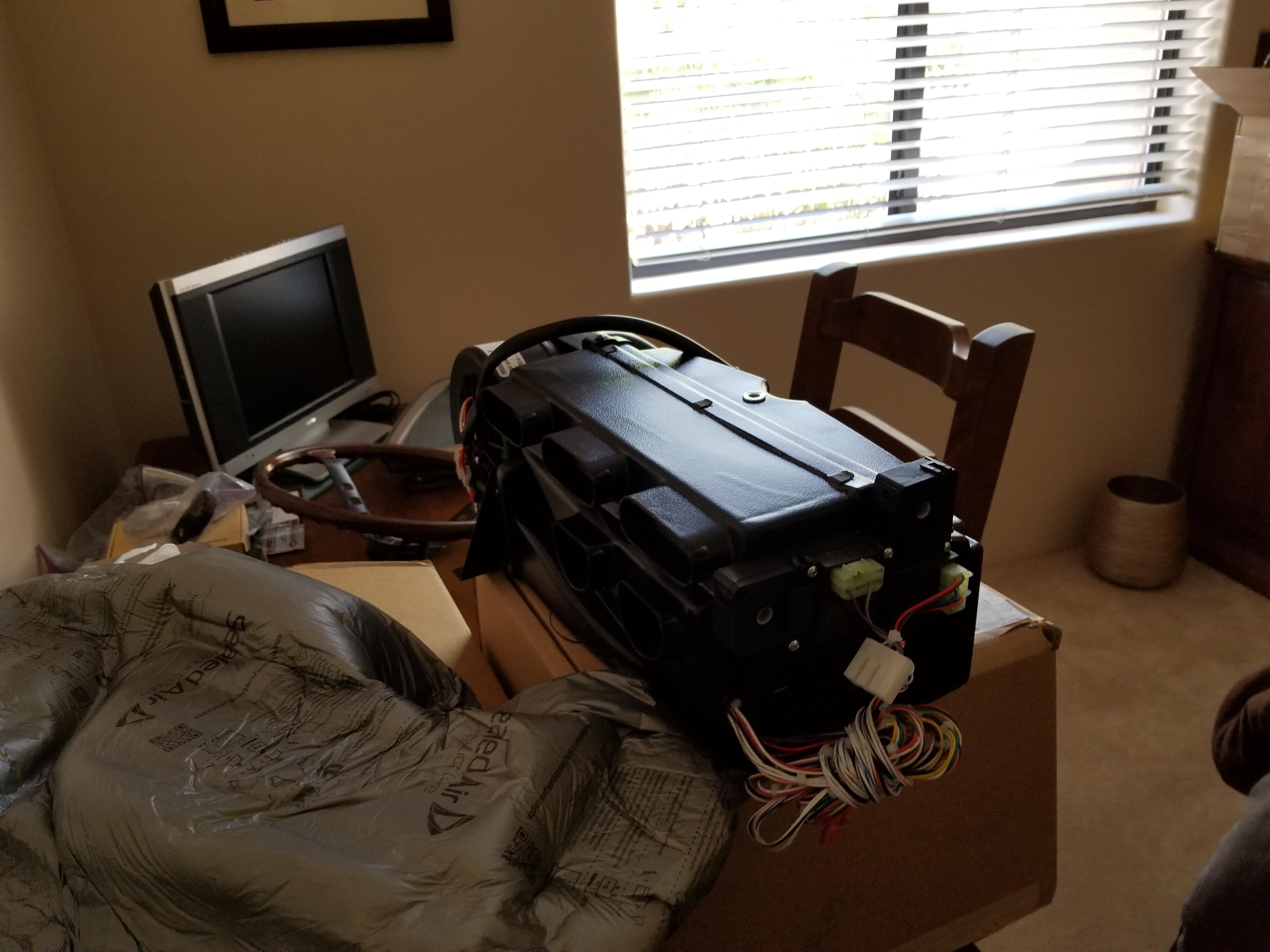
The Gen II is a replacement for the original heater core, air box, and under-dash AC evap. As you can imagine the gen ii is quite a bit smaller than the original components, but it is a universal system and therefore it needs to be shoe horned into a space under the original dash. Because I removed so much original material, I thought that I would be able to fit the combination evaporator/heater and air box above the transmission tunnel and behind the instrument panel. This gets it away from the passenger footwell and centers the defrost and climate openings. I found someone that had done something similar so I was fairly confident that I would not have a fitment issue with the dash. Brackets are provided with the Gen II but I did not find them to be particularly useful. Mounting is fairly straightforward, but if you are like me sometimes it takes a few proto-types to get something that satisfies you.
Mounting the Evaporator
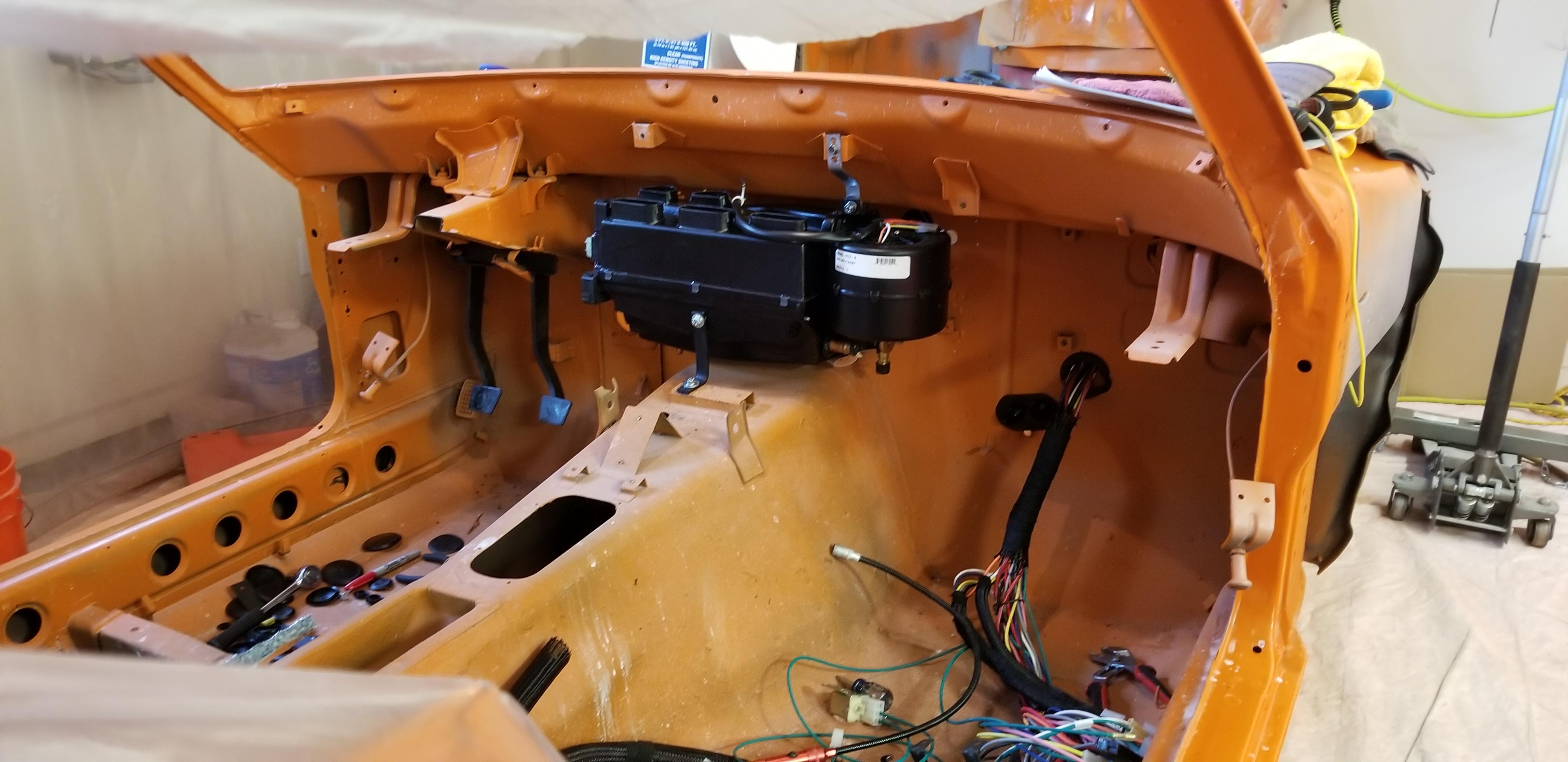
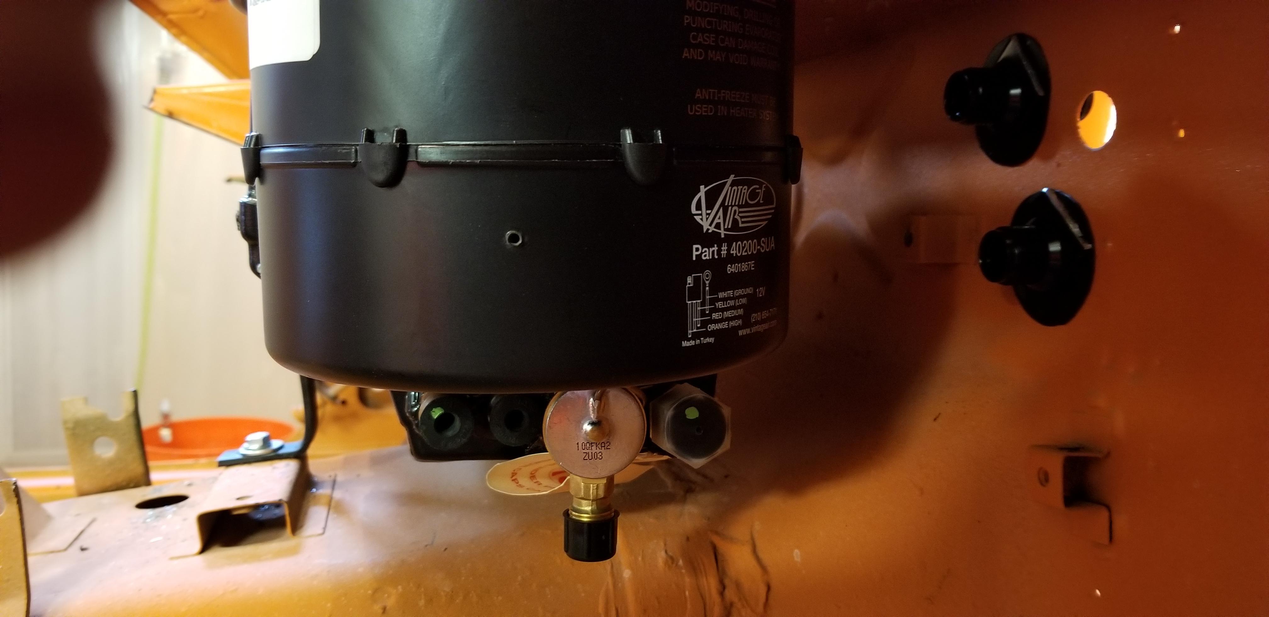
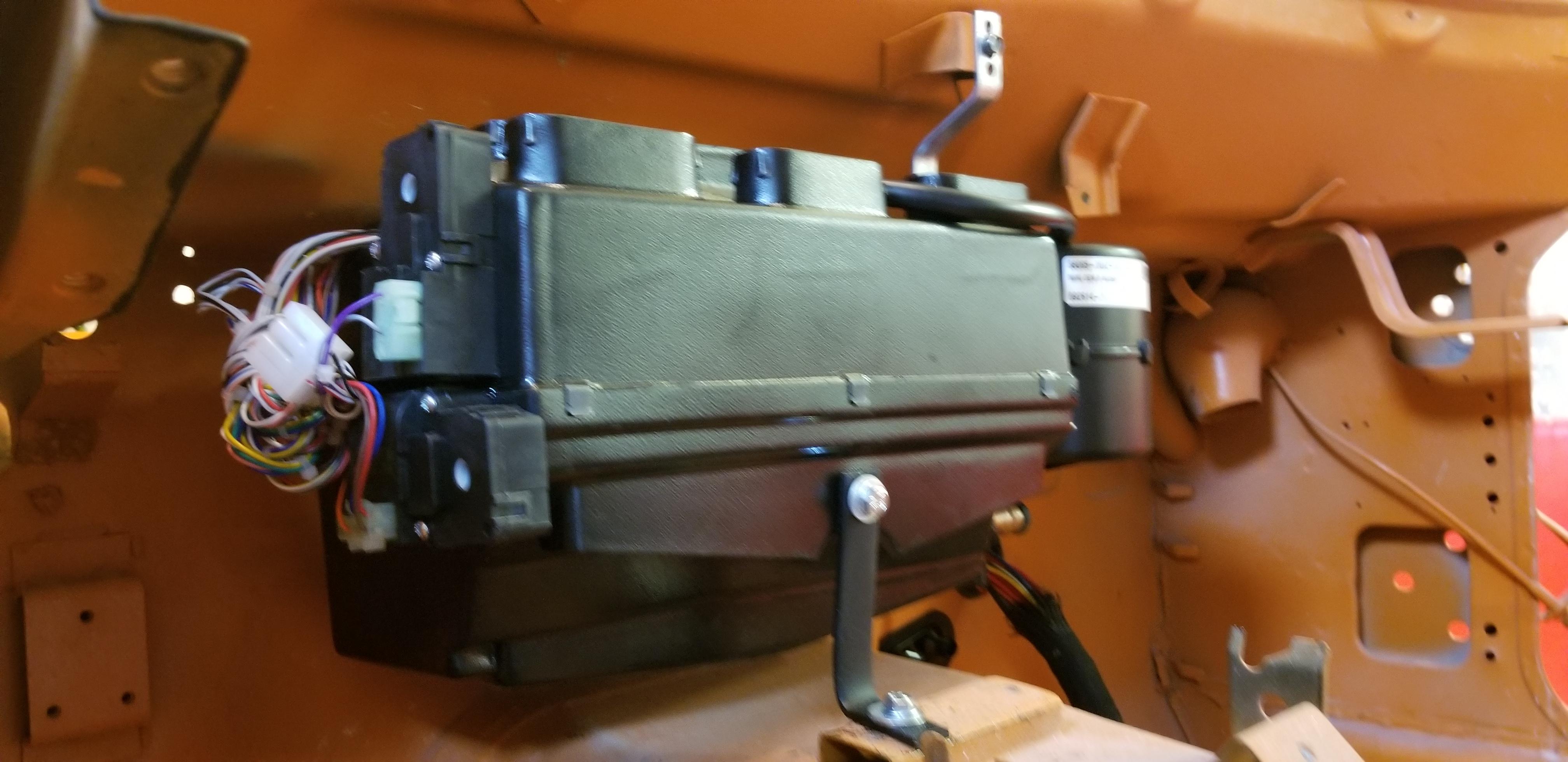
Once the evaporator is in place you can decide where hoses need to enter/exit the firewall. It is always nice to use the original holes, but you need to consider the radius of the bends for the hoses as they do not like to make sharp turns. I decided to install bulkheads for both the AC hoses and the heater hoses. I like this luxury because if the engine has to come out or if anything goes wrong with the evaporator/heater then disassembly stops at the firewall. Also if any of the hoses fail you don’t have to disconnect at the evaporator to replace an engine bay hose and vice versa. Working these stiff hoses and close connections under the dash is not the most comfortable task, The only downside that I can think of regarding bulkhead connections is that there are additional breaks in the hoses that now require some sort of mechanical connection and this is yet another opportunity for a leak. I did not have to cut any additional holes in the firewall but I would recommend that you buy individual bulkhead connectors as opposed to 2-way or 4-way bulkheads. This probably makes it easier to use the original holes.
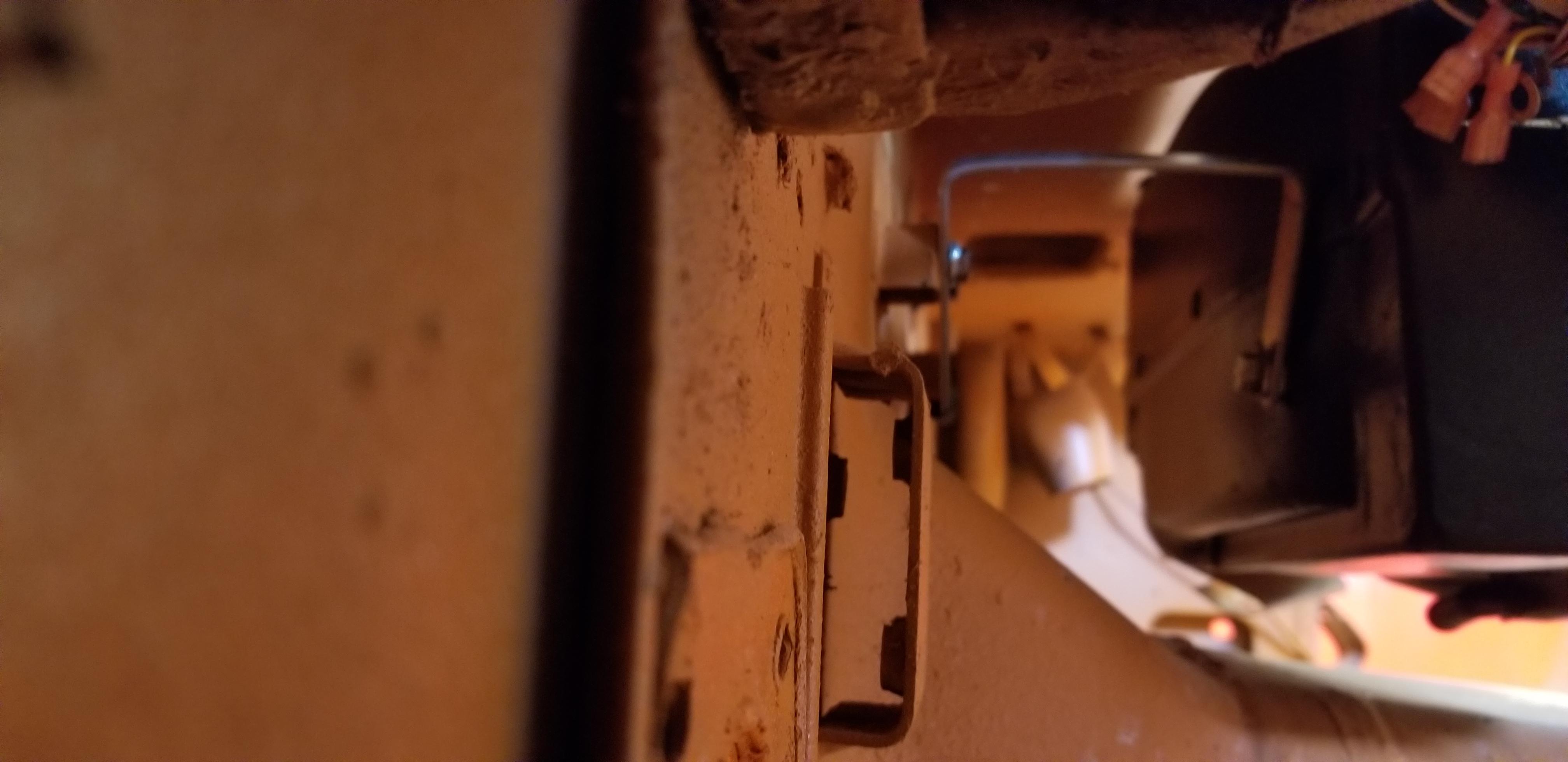
Bulkhead Connections
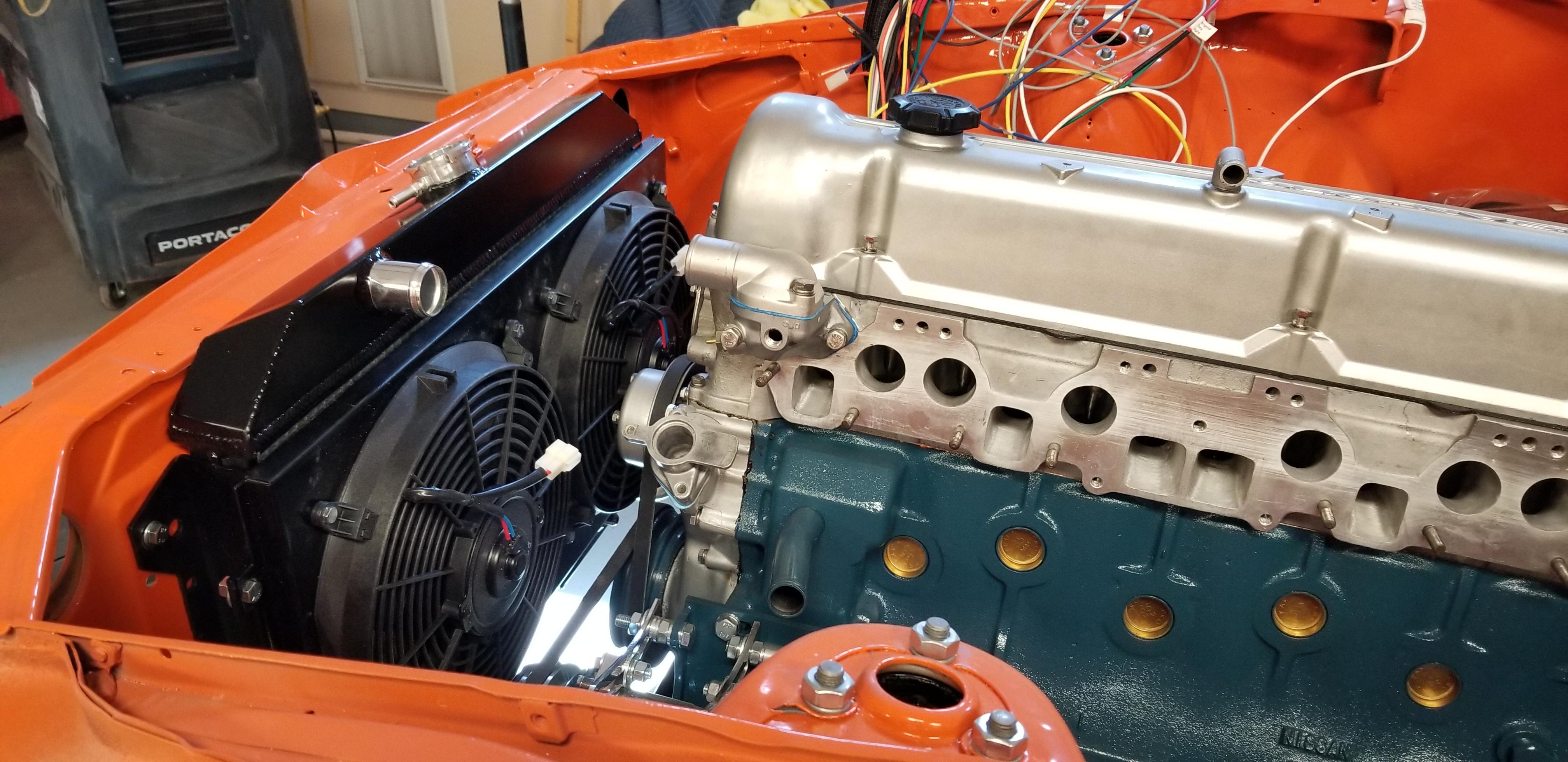
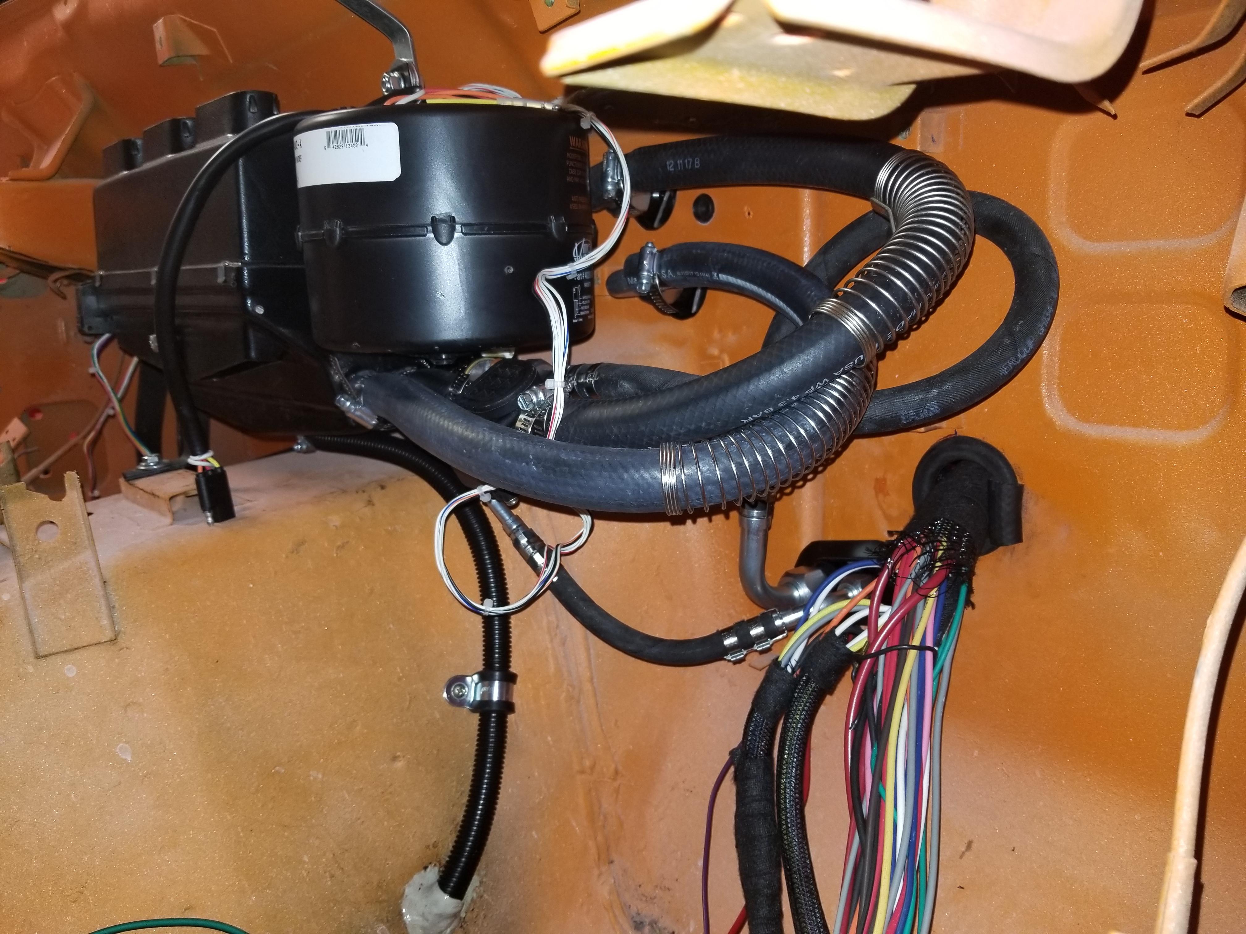 water connections are behind the evap, compressor connections are near the main harness entry.
Those are EZ-coils fitted on the hoses to help keep them from collapsing due to a sharp radius
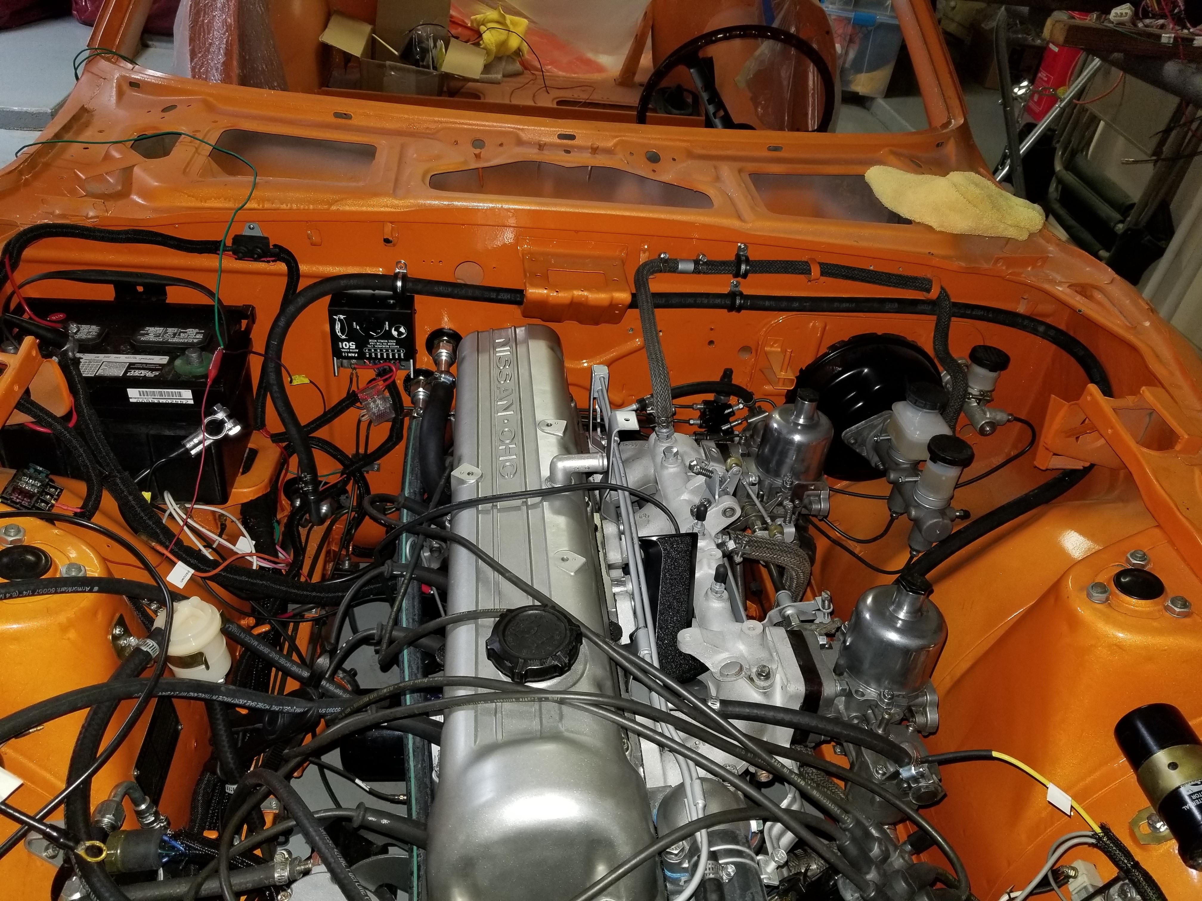
you can see the water connections on the passenger side of the engine just below the level of the valve cover. Compressor lines enter the bay just above the passenger frame rail.
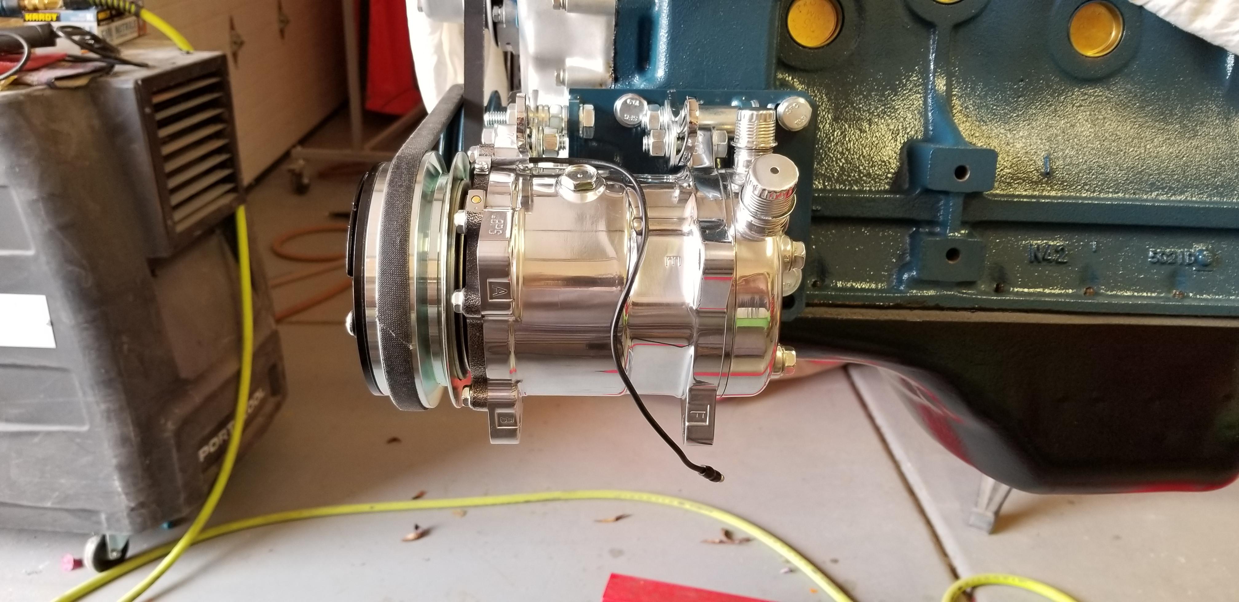
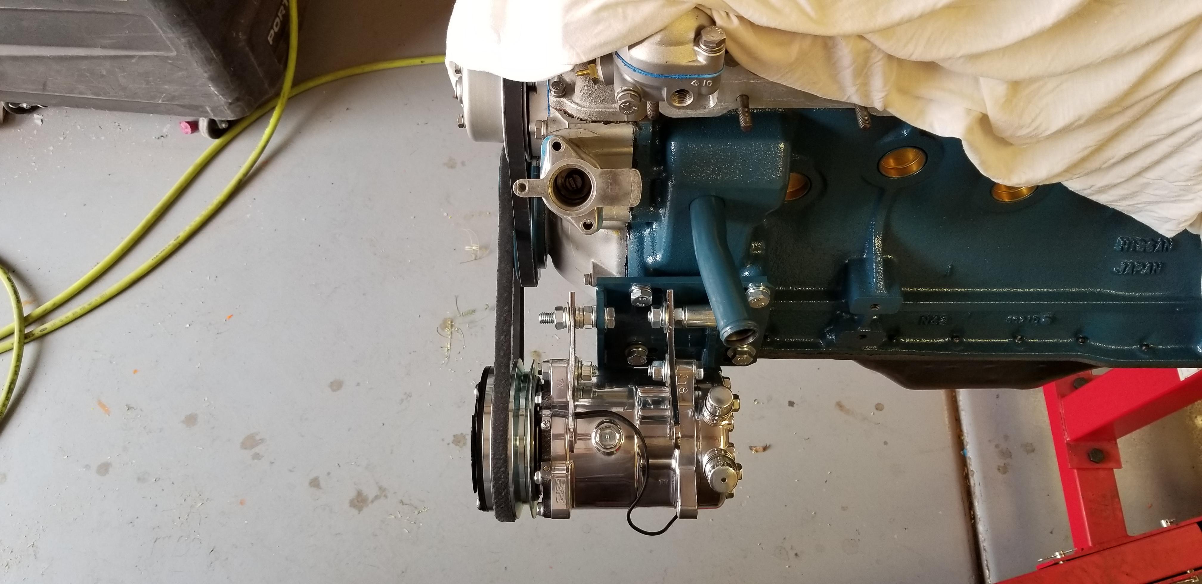
I would have preferred to do all of the hose routing with the engine out of the way, but I was concerned that I could not visualize every aspect. The AC compressor is a bit of a chore to mount so I will do that while the engine is on a stand. Here is what is being replaced – a Nissan bracket, and a sanden compressor. The original compressor is much lighter than most that were used in the day like York, but the original combination still weighs 24 lbs.
Original Bracket and Compressor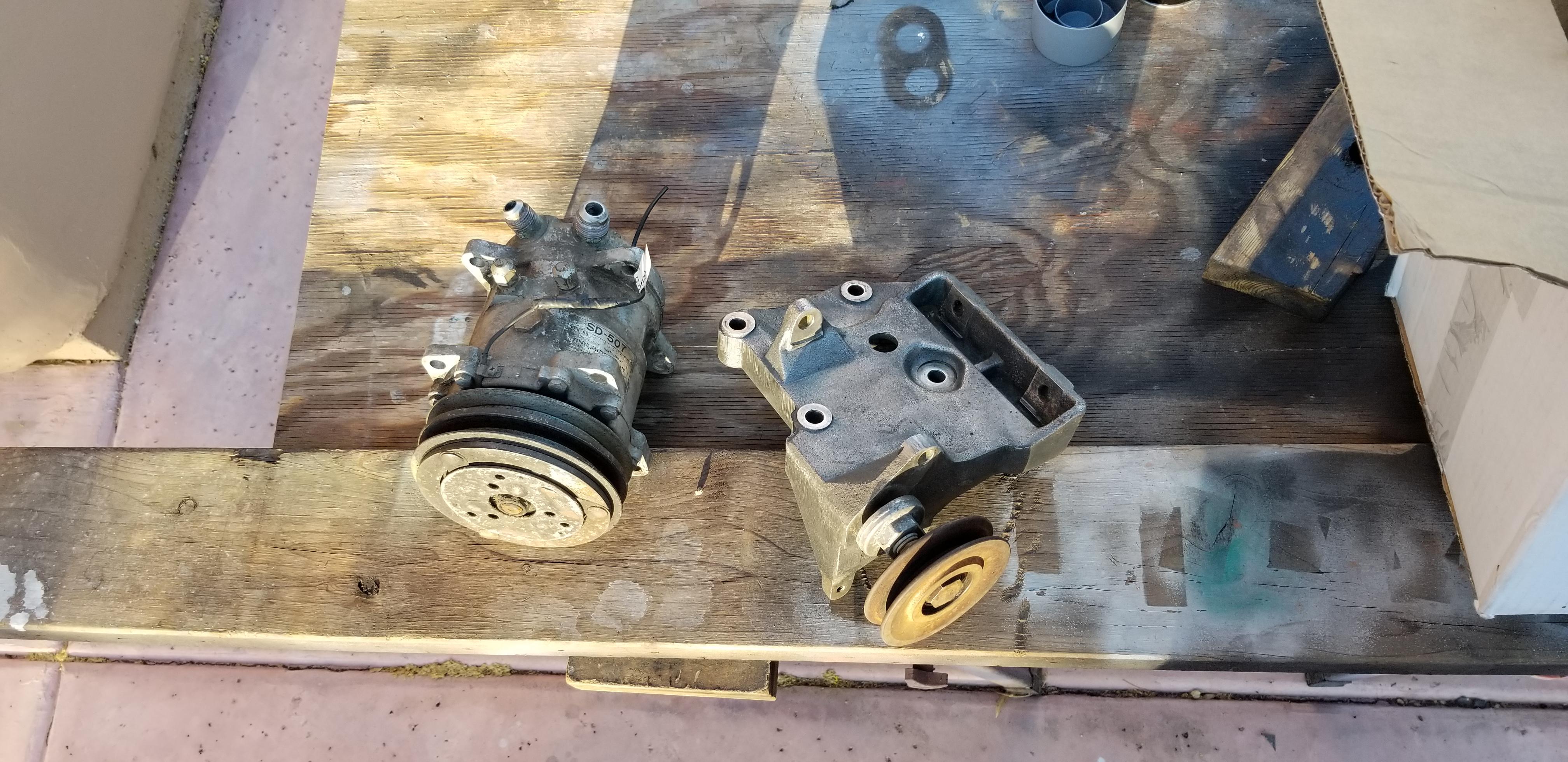
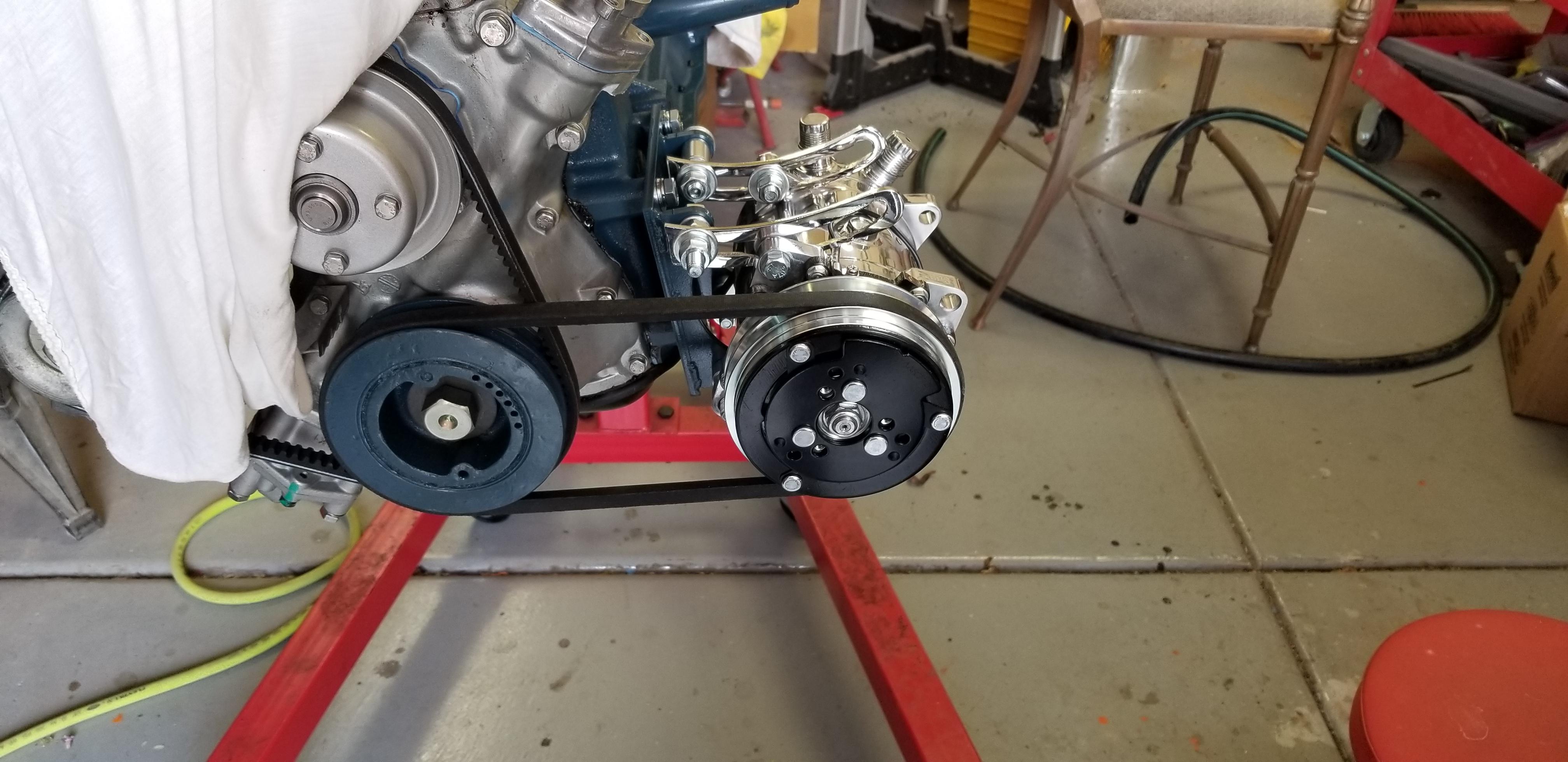
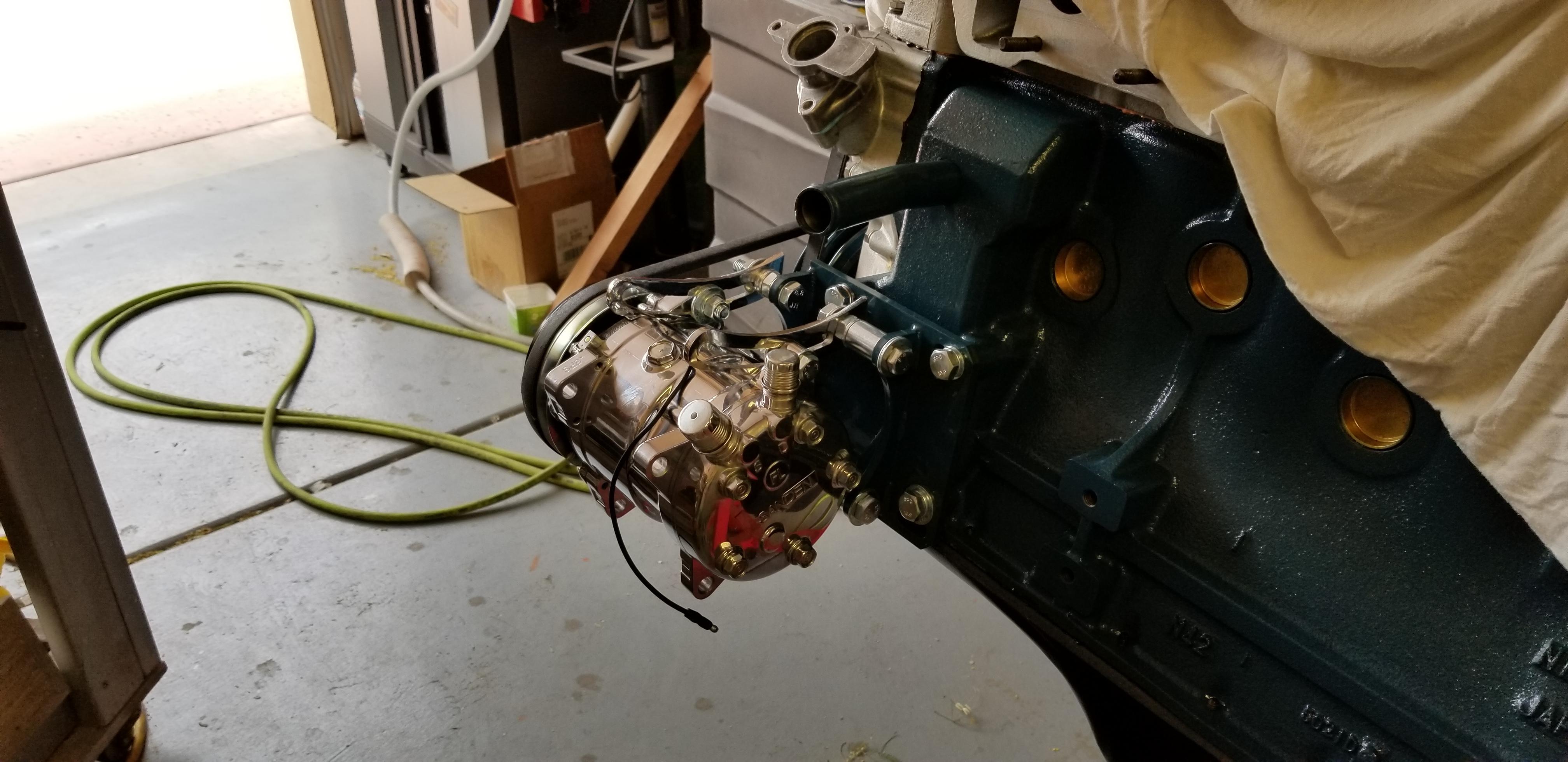
I tried to use the original bracket. Even though it is heavy and bulky it is clearly better because the compressor can be mounted so that it does not have to move to install a v-belt. There is an integral idler pulley that is adjustable. I spent valuable time cleaning the bracket and the pulley in preparation for painting, but alas I could not figure out a good way to modify it to accept the new compressor and properly align it with the engine pulley. The bracket that I purchased from Vintage is simple (no idler pulley) but it is made to convert a York bracket. Unfortunately, it does not line up with the bucket’s pulley. So my choices were to somehow modify the simple bracket or build a new bracket. I decided to attempt a mechanical solution as opposed to modifying the bracket by welding a piece on. The problem really has two pieces: the compressor must align with the engine pulley and because there is no Idler pulley it must rotate to install and adjust the v-belt. Here is what I came up with. It is 9lbs lighter. I will continue to look for a more elegant solution with an idler pulley, but I need to get the engine back in the car.
NEW AC Bracket and Compressor
With the engine and radiator in place it is an easy task to route the Compressor hoses to the bulkhead. Vintage offers a connect system called “easy clip”. I have not used this before but it allows me to construct all of the hoses myself without the usual expense of a crimping tool. This will make start-up of the AC system much simpler, because I will be able to go to a shop and only require evacuation, drying and filling to get the system working. This should take about an hour as opposed to waiting for someone to construct the crimp hoses and depend on someone else to route the hoses to my satisfaction. Hopefully, the easy clip system works well and does not leak.
Condenser
The condenser and drier were both part of the gen II kit. Bracketing the condenser was fairly easy. You need to take into account the holes in the radiator support as the hose that sources the drier must go through the support. It would have been nice to mount the drier ahead of the support where the air is coolest but it was more convenient for me to put it on the engine side. I converted to an aluminum radiator with an electric fan so I installed a trinary switch on the drier. So, the routing of the hoses is: Evap to Comp, Comp to condenser, condenser to drier and drier back to the evap. The route that I took was evap across the firewall to the comp mounted driver side low, from the compressor thru the radiator support across the condenser to a connection on the passenger side of the condenser from the condenser thru the radiator support to the drier, from the drier along the passenger frame rail to the firewall to the evap.
That is a 2 row aluminum radiator painted black with a dual electric fan setup. I still think that it is strange to use a 2 row, but based on what I read I convinced myself that 2 rows were actually better than 3 or 4 for the same overall length and width.
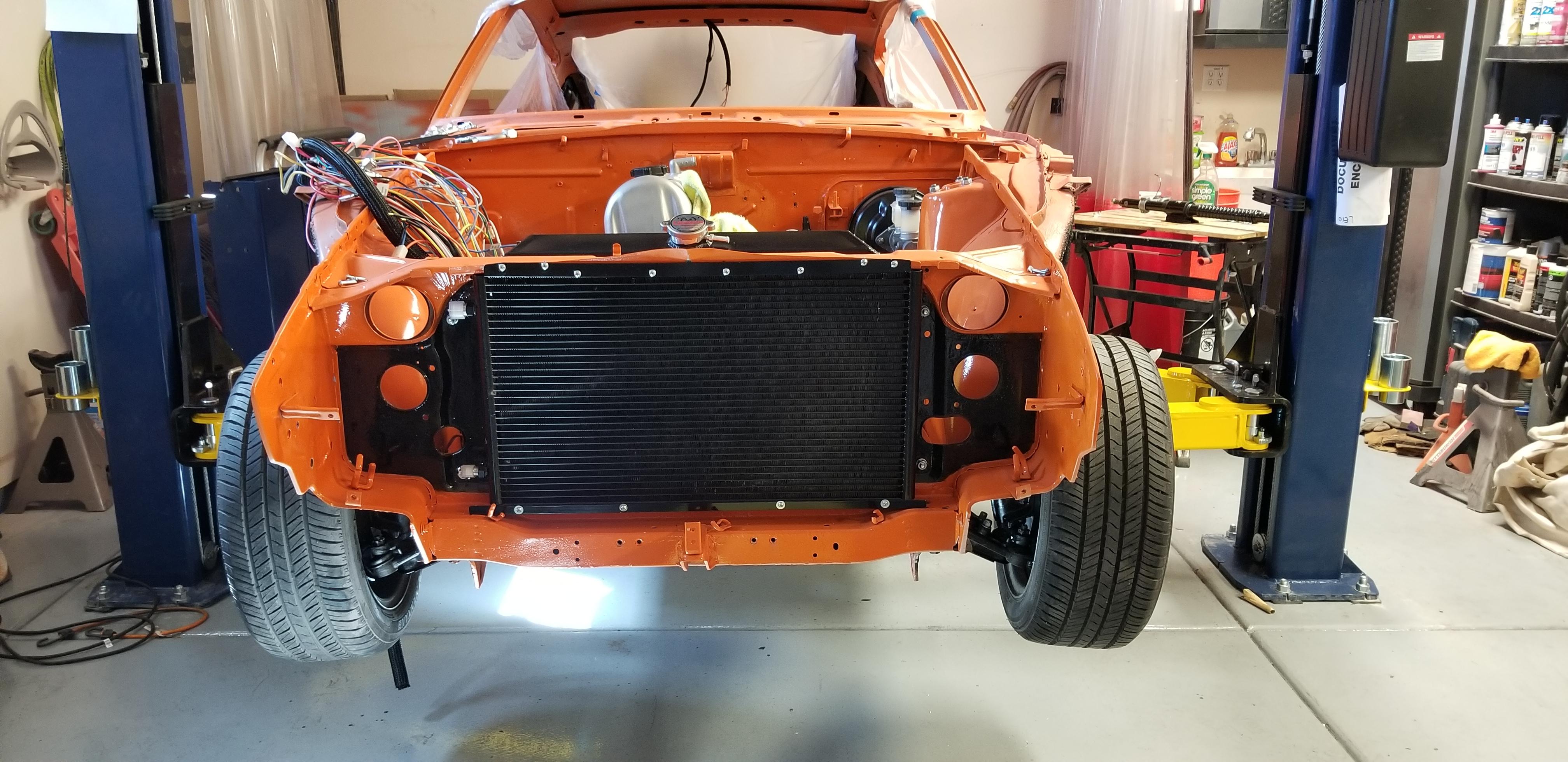
The condenser is visible here - in front of the radiator
Climate Control Panel
The last piece of the puzzle – mounting the controls. When this project began, I had no idea what I was going to do with regard to the climate control panel. Trust me this restoration has had enough challenges, but I wanted the controls to look they were part of the car. Originally, I envisioned the new panel hidden behind the original panel with mechanical linkages to control the system. I ordered a panel from vintage air, their least expensive. It allows for 4 slide type controls: AC compressor on/off combined with AC temperature control, Heater temperature control, Fan speed control, and Mode (defrost, feet, body, body+feet) control. Now that I have good handle on the mounting of the evaporator and know that the dash will fit without interfering with the evap I can consider using the original Datsun climate control panel which had the original mechanical controls for the vent, heater and defroster. The bucket had an aftermarket AC system, but it did not have anything integrated so the compressor control and the AC temperature control were all hung external to the dash. The Datsun climate control panel accommodates three slide controls: outside air, heater temperature, mode (defrost, feet, body, body+feet) control; and a rotary fan speed control. The controls for the original AC system were appended to the dash and did not compliment the look and feel of the car.
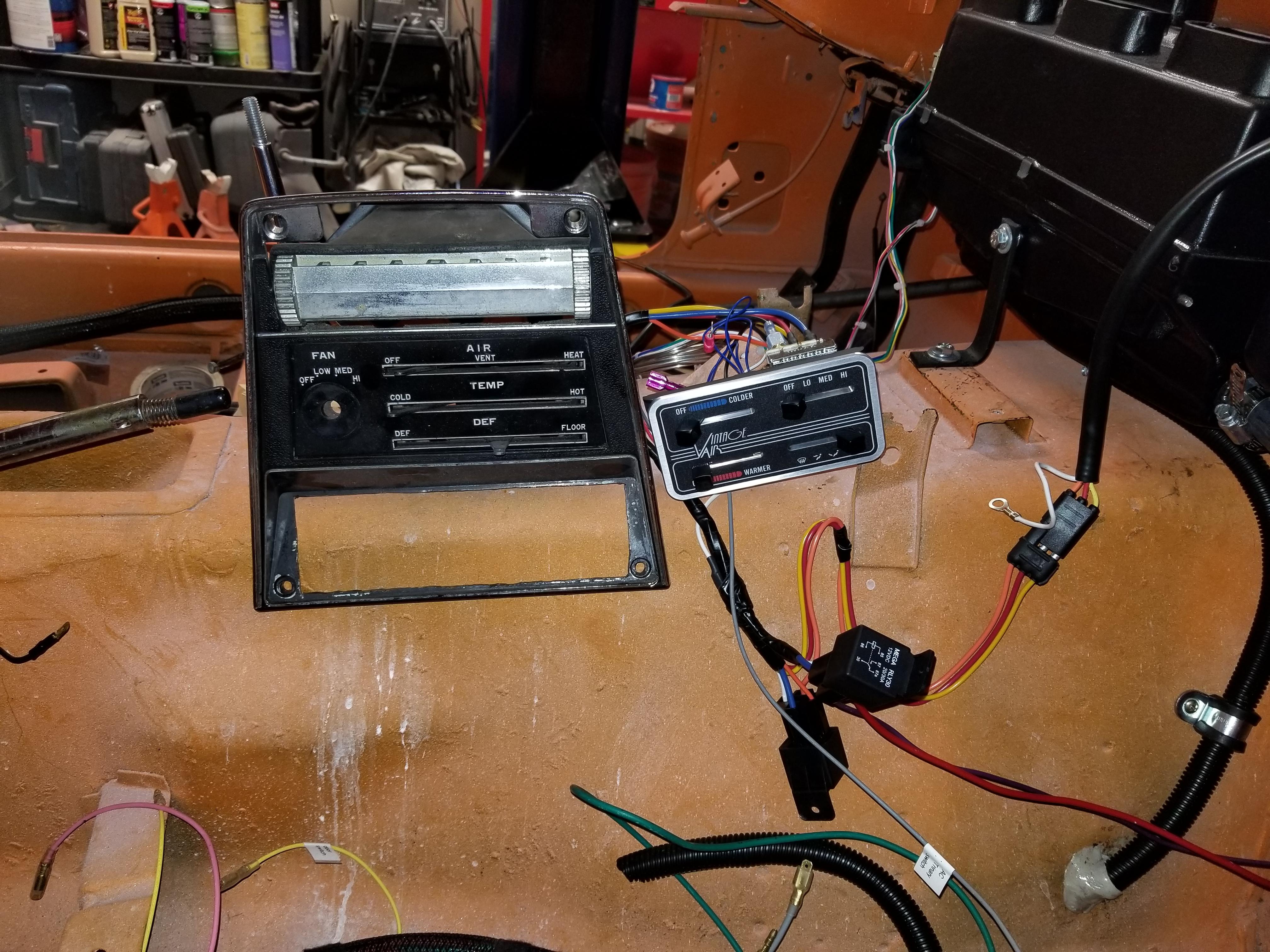 The original climate control panel and the vintage air panel
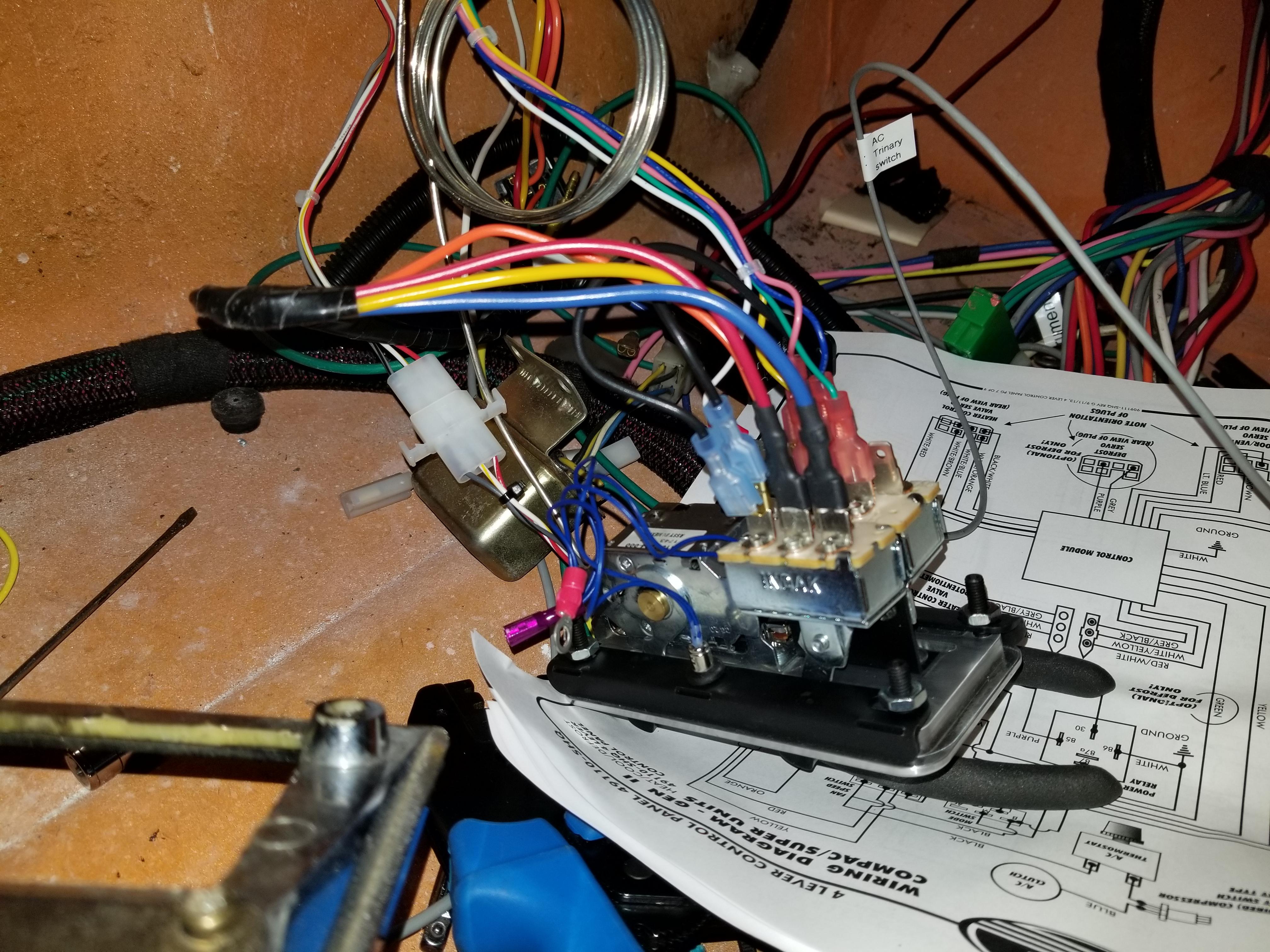
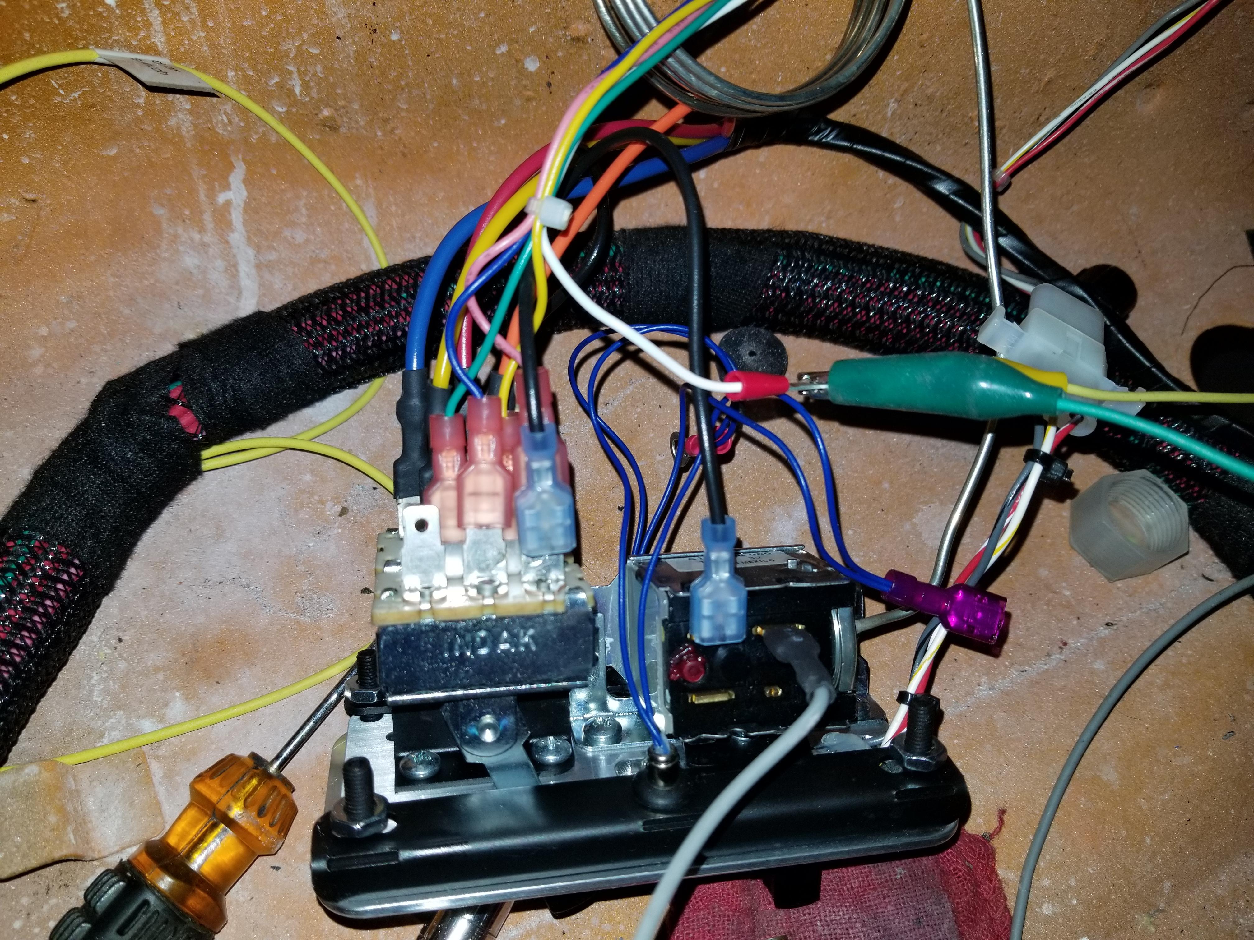
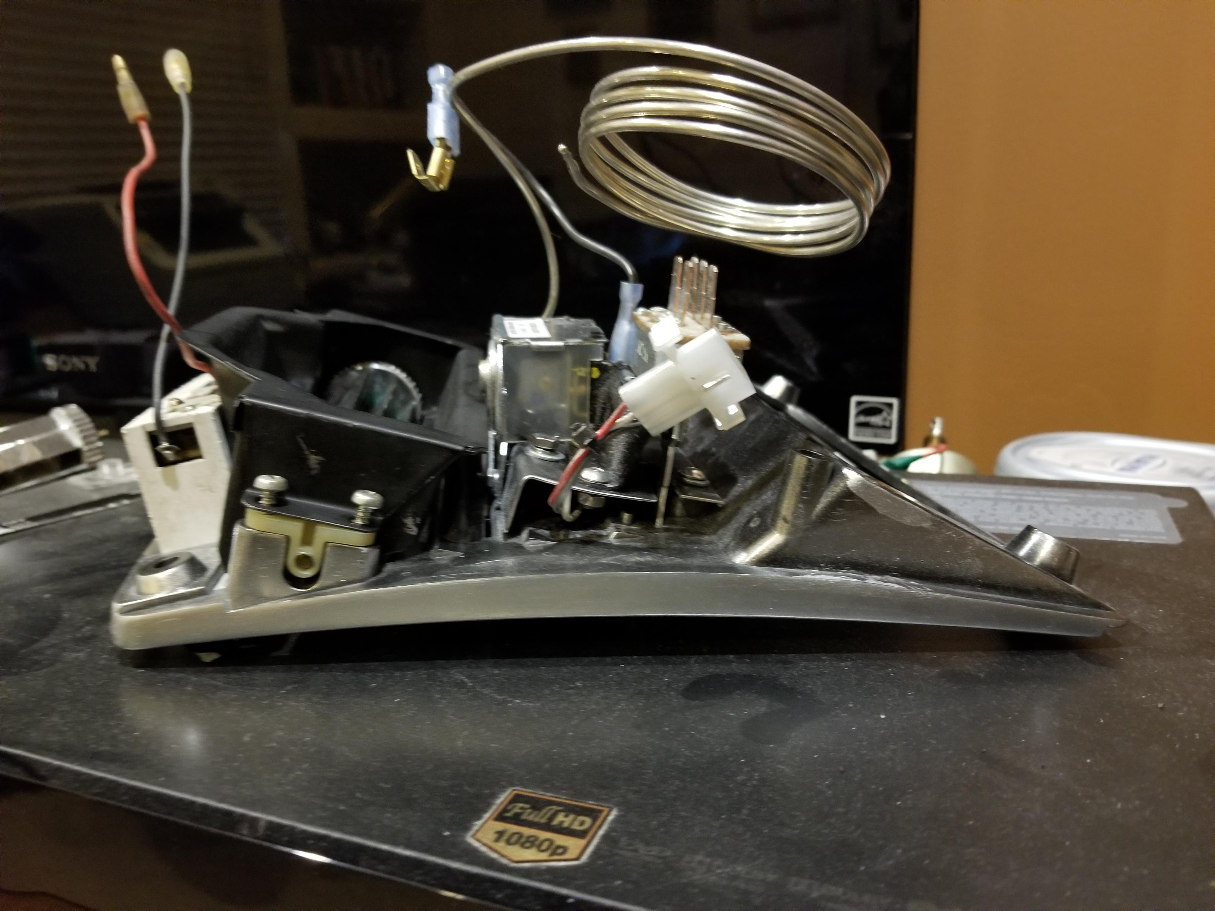
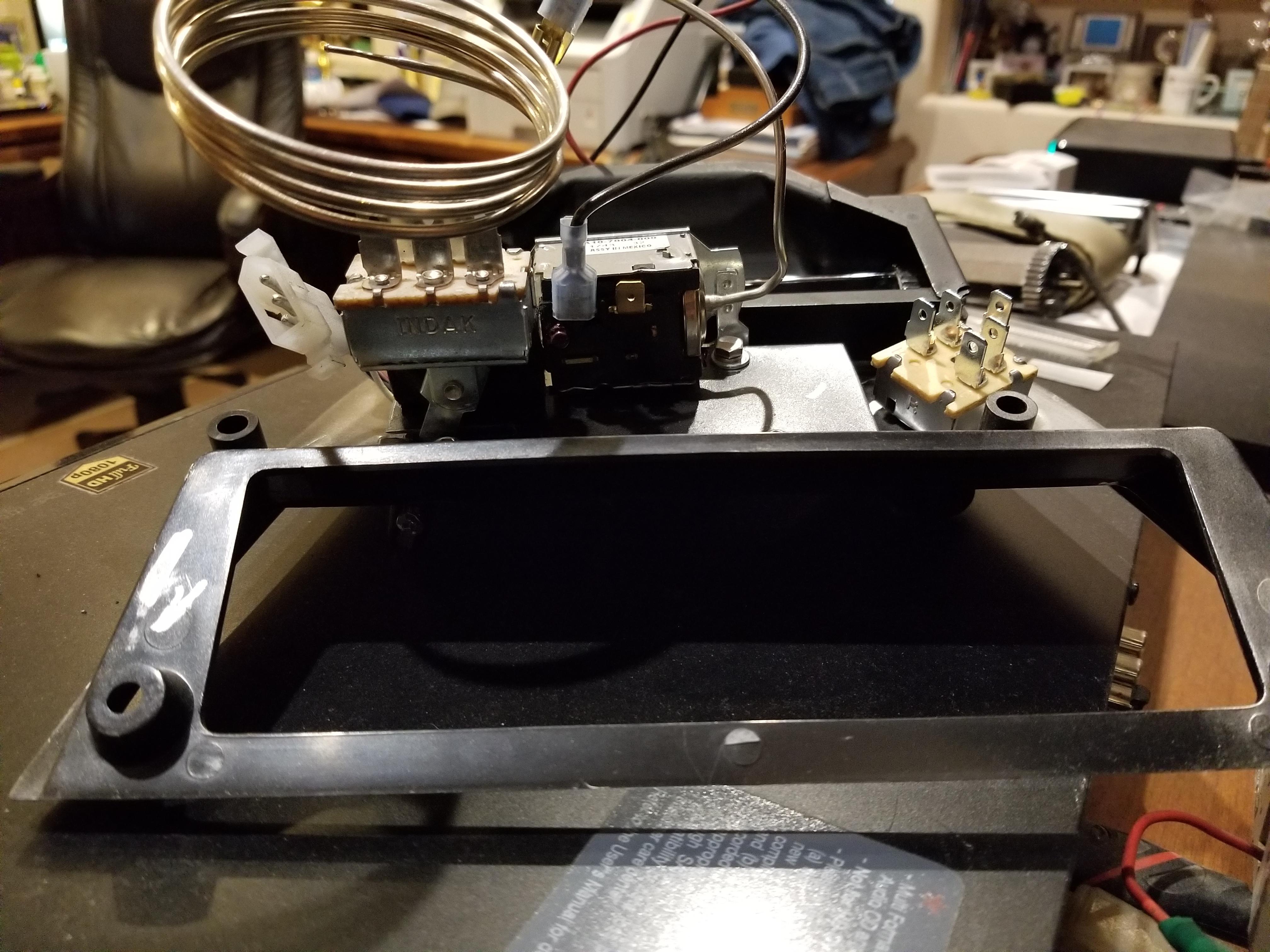
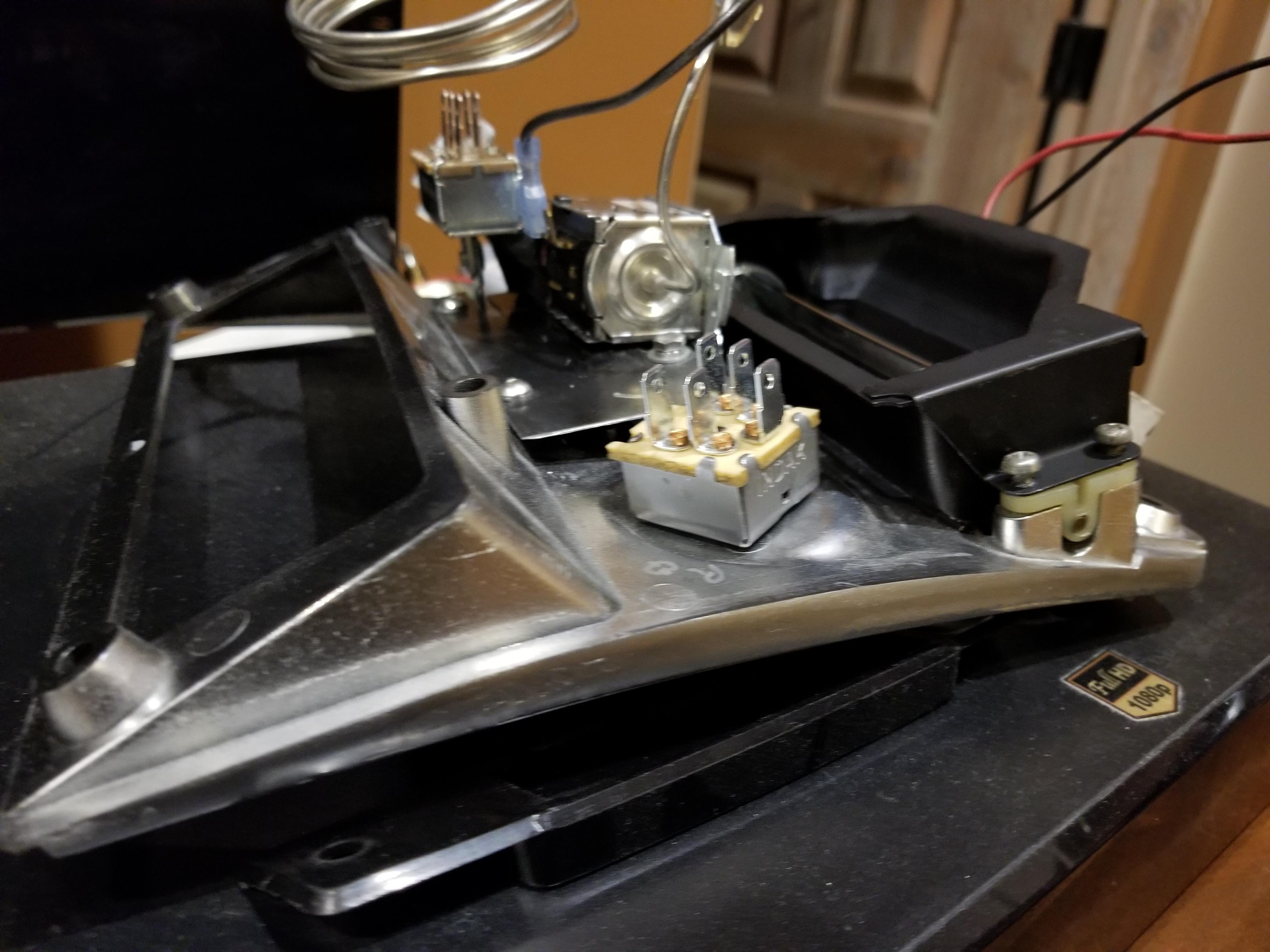
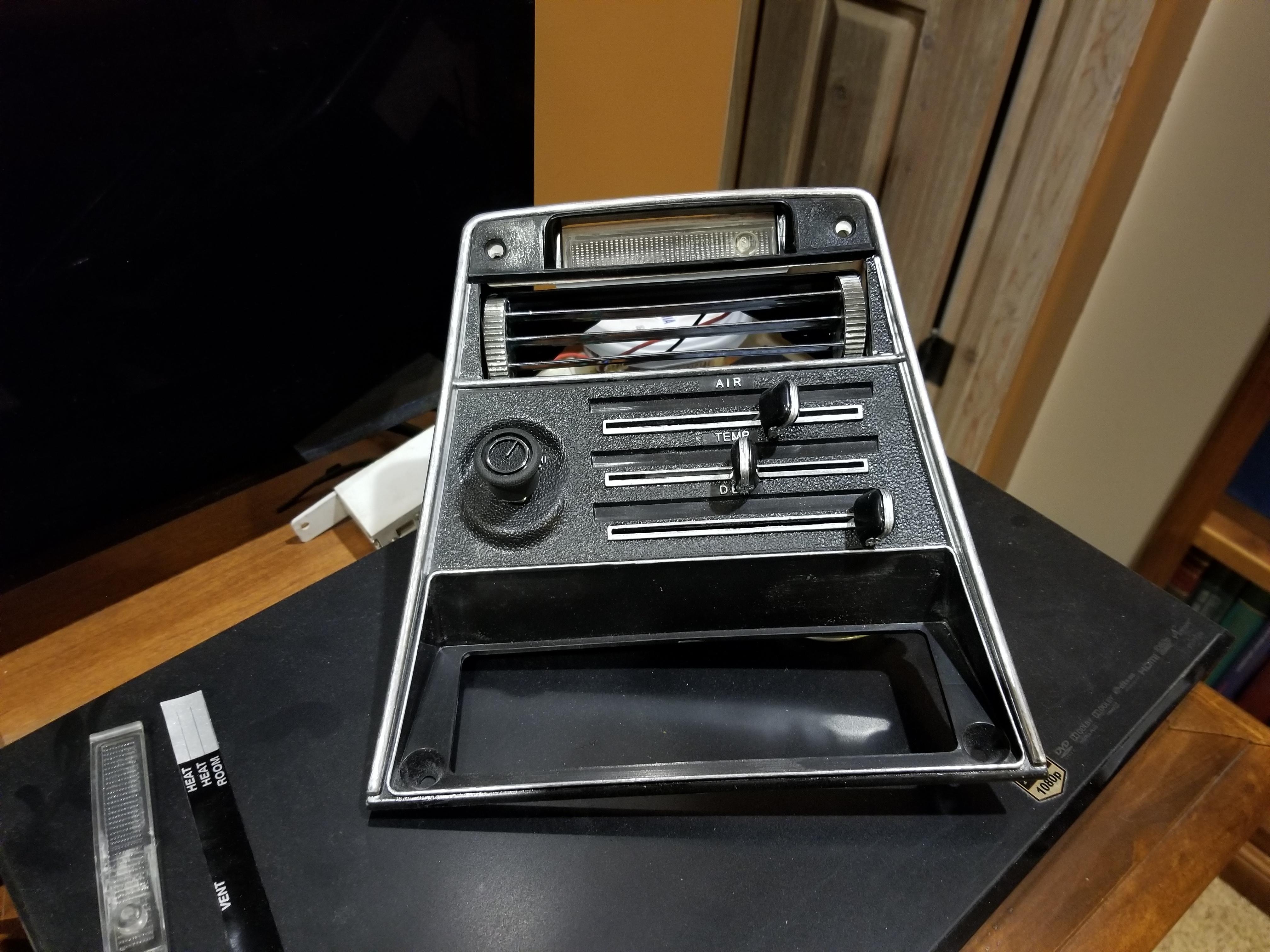
I decided that I was going to attempt to integrate the vintage air controls into the 240z panel. My control panel was not in very good shape so I decided to use it to trial fit everything. I opted for the luxury of replacing my panel with a new one. MSA does make one – it’s approximately $130. Its plastic, well built, but nothing special. They have a slightly more expensive version with chrome accents – I was not smart enough to order that version, so I spent more to have the fun of trying to do chrome accents myself. The first obvious difference between the original and the vintage controls is the fan control. I ordered a rotary fan switch from vintage air to replace the slider that I originally purchased. The hole in the 240z panel must be opened a bit to accommodate the vintage air control. If you go this route, remember to be careful as you are working with plastic, so cracking is a real possibility. Next, I removed each of the slide switches from the vintage air panel. In my opinion the best/easiest way to integrate them into the 240z panel was to create an intermediate metal panel to house the vintage air controls and then mount the intermediate panel onto the 240z plastic panel. The metal panel should help distribute the forces of the sliders and will allow me to more easily position the sliders where I need them. It’s not as easy as it sounds. The travel of the vintage air sliders is quite a bit smaller than the original 240z controls. I considered mounting the sliders a few inches back from the 240z panel which would make the slider travel more similar to the original but it complicated everything else so I rejected the idea. The length of the vintage air slider mechanisms is also different than the original 240z controls. The vintage air heater temperature control is a bit hooky in my opinion. It is mounted to the vintage air panel by being squeezed by their bracket. There is no provision to screw it to a panel. It’s quite small. I used thin aluminum sheet stock to build trial configurations. It’s easy to bend and easy to cut and you can expose a lot of issues very quickly by using a proto-typing process. The AC control is relatively large. I decided to fit it into the top slot of the plastic panel labeled “AIR”. In my opinion - this is where it fits best. You can mount it without a lot of difficulty with one exception – the length of the slide control is too short. If you choose to go this route don’t purchase the vintage air panel (it’s a waste of money), and when you order the controls make sure that they provide full length sliders. When they build a kit with their panel, they cut the sliders to fit their panel and it is too short for the Datsun panel. I very carefully bent the L shaped bracket flat. I then removed enough material from the bracket to allow the slider to protrude through the plastic panel enough so that I could attach a plastic knob to it. I wanted to use the original 240z knobs to help disguise the vintage air system. One of my knobs was cracked and so I searched for a replacement. I found some new ones at Banzai Motor Works that were reasonable. The heater temperature control will fit just below the AC control. I built a small aluminum bracket that pinches the heater control and attaches to the climate control panel. Lateral movement of the heater control is prevented by the aluminum bracket and vertical movement is prohibited because the heater control is held in place by the ac control above it. The mode control will fit in the climate control panel’s third (lowest) slot. Here is an image of the original control panel with all of the controls mounted to it. Also, you need to seal off the cowl vent because there is no provision for the vintage air system to utilize that vent. The only fresh air vent system that you will have will come from the vents on the driver and passenger side which are controlled by individual mechanical cables. These vents actually get their air thru the ducts to the opening in the radiator support. The bottom line is that the original 240Z panel will remain in-tact and the new system will seamlessly fit behind it. You will not be able to tell that the entire climate system has been upgraded.
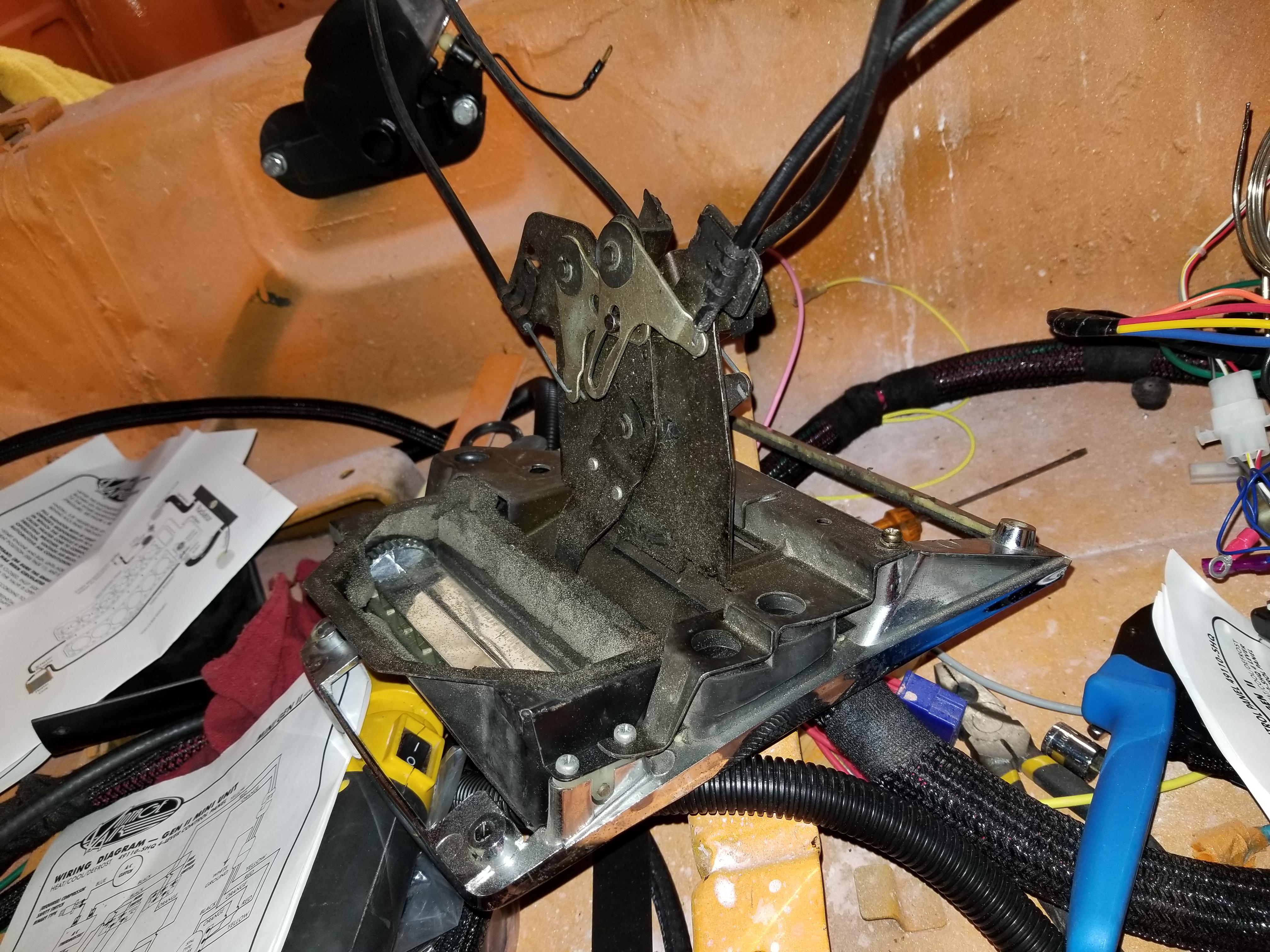
vintage air controls
Integrated Panel
CONCLUSION
If you choose to upgrade your AC system and you opt to integrate the controls into the original climate control panel you can benefit from my mistakes. Do not order the panel/control kit. Instead order the individual switches with full length sliders. Make sure that you order the rotary fan control and not the slide fan control switch.
In the spirit of full disclosure I have not fired-up the AC system yet. Having said that, based on previous experience I believe that Vintage Air has done a great job providing a terrific system with more than adequate documentation. I especially like the reduction in physical size and weight. I also like the electronic controls as opposed to mechanical – cable stretch and loose cable connections are a thing of the past. I appreciated being able to make my own compressor hoses (hope they are solid and do not leak). I do wish that they would come up with a universal compressor mount with an idler pulley. All in all, it is a great system. It takes a fair amount of time and effort to install, but I believe you will be happy with the result. I will try to answer any questions that you might have. Good Luck.


Recommended Comments
There are no comments to display.